Table of Contents
Advertisement
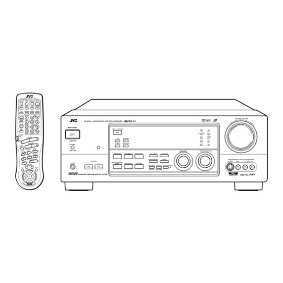
AUDIO/VIDEO CONTROL RECEIVER
AUDIO/VIDEO-RECEIVER MIT STEUEREINHEIT
AMPLI/TUNER DE COMMANDE AUDIO/VIDEO
GEINTEGREERDE AUDIO/VIDEO-VERSTERKER
RECEPTOR DE CONTROL DE AUDIO/VÍDEO
RICEVITORE DI CONTROLLO AUDIO/VIDEO
RX-884RBK
RM-SR884RU REMOTE CONTROL
TV/CATV
VCR1
ANALOG
AUDIO
/DBS
/DIGITAL
DVD
VCR1
VCR2
VIDEO
CD
TAPE/MD
PHONO
FM/AM
CNTR TONE
CNTR
MENU
TV/DBS
1
2
3
SURROUND
TEST
ENTER
REAR L
MODE
RX-884R AUDIO/VIDEO CONTROL RECEIVER
4
5
6
SOUND
EFFECT
REAR R
CONTROL
7
8
9
/P
STANDBY
CD
SEA MODE
SUBWOOFER
DISC
10
0
+10
RETURN
FM MODE/MUTE
100+
AUDIO/TV
/VCR
CATV
STANDBY/ON
/DBS
POWER
_ ON — OFF
SPEAKERS
PHONES
1
CONTROL
VCR1
TAPE
EXIT
SET
COMPULINK
Remote
ENHANCED COMPULINK CONTROL SYSTEM
DOLBY SURROUND
EON
TA/NEWS/INFO
PTY SEARCH
DISPLAY MODE
MULTI JOG
DSP MODE
SEA MODE
DIGITAL INPUT
FM/AM TUNNING
TUNER PRESET
TUNER/SEA MEMORY
FM MODE
BALANCE/SURROUND
2
ADJUST
SEA ADJUST
SETTING
SOUND SELECT
LOUDNESS
ONE TOUCH OPERATION
INPUT ATT.
SOURCE NAME
INSTRUCTIONS
BEDIENUNGSANLEITUNG
MANUEL D'INSTRUCTIONS
GEBRUIKSAANWIJZING
MANUAL DE INSTRUCCIONES
ISTRUZIONI
MASTER VOLUME
D I G I T A L
–
+
DVD
CD
TV SOUND/DBS
PHONO
VCR 1
TAPE/MD
FM
VCR 2
VIDEO
AM
SOURCE SELECTOR
VIDEO
S-VIDEO
VIDEO
L
AUDIO
R
For Customer Use:
D I G I T A L
Enter below the Model No. and Serial
No. which are located either on the rear,
bottom or side of the cabinet. Retain this
information for future reference.
Model No.
Serial No.
LVT0016-001A
[E]
Advertisement
Table of Contents

Related Manuals for JVC RX-884RBK


Summary of Contents for JVC RX-884RBK
- Page 1 AUDIO/VIDEO CONTROL RECEIVER AUDIO/VIDEO-RECEIVER MIT STEUEREINHEIT AMPLI/TUNER DE COMMANDE AUDIO/VIDEO GEINTEGREERDE AUDIO/VIDEO-VERSTERKER RECEPTOR DE CONTROL DE AUDIO/VÍDEO RICEVITORE DI CONTROLLO AUDIO/VIDEO RX-884RBK RM-SR884RU REMOTE CONTROL TV/CATV VCR1 ANALOG AUDIO /DBS /DIGITAL VCR1 VCR2 VIDEO TAPE/MD PHONO FM/AM CNTR TONE CNTR...
- Page 2 L or coloured red. IF IN DOUBT - CONSULT A COMPETENT ELECTRICIAN. Per I’ltalia: “Si dichiara che il questo prodotto di marca JVC è conforme alle prescrizioni del Decreto Ministeriale n.548 del 28/08/95 pubblicato sulla Gazzetta Ufficiale della Repubblica Italiana n.301 del 28/12/95.”...
- Page 3 CAUTION To reduce the risk of electrical shocks, fire, etc.: 1. Do not remove screws, covers or cabinet. 2. Do not expose this appliance to rain or moisture. ACHTUNG Zur Verhinderung von elektrischen Schlägen, Brandgefahr, usw: 1. Keine Schrauben lösen oder Abdeckungen enternen und nicht das Gehäuse öffnen.
- Page 4 Caution –– POWER switch and STANDBY/ON This apparatus is provided with a POWER switch to be able to minimize power consumption for safe use. Therefore, 1. When doing initial setting, complete all the connections required, connect the mains plug into the wall outlet, and set the switch to ON.
- Page 5 Spacing 15 cm or more Abstand von 15 cm oder mehr Dégagement de 15 cm ou plus Minstens 15 cm tussenruimte Espacio de 15 cm o más 15 cm di distanza o più RX-884RBK Floor Boden Plancher Vloer Piso Pavimento...
-
Page 6: Table Of Contents
Table of Contents Parts Identification ... 3 Getting Started... 4 Before Installation ... 4 Checking the Supplied Accessories ... 4 Connecting the FM and AM (MW/LW) Antennas ... 5 Connecting the Speakers ... 6 Connecting Audio/Video Components ... 9 Connecting the Power Cord ... 13 Putting Batteries in the Remote Control ... - Page 7 Searching a Disc (Only for the CD Player) ... 58 Using the User File (Only for the CD Player with the User File Function) ... 60 Entering the Disc Information ... 61 Operating JVC’s Audio/Video Components ... 63 Operating Other Manufactures’ Components ... 67 Troubleshooting ... 74...
-
Page 8: Parts Identification
Parts Identification Become familiar with the buttons and controls on the receiver before use. 3 4 5 6 8 RX-884R AUDIO/VIDEO CONTROL RECEIVER STANDBY STANDBY/ON POWER _ ON — OFF SPEAKERS PHONES COMPULINK Remote ENHANCED COMPULINK CONTROL SYSTEM Ÿ RM-SR884RU REMOTE CONTROL TV/CATV VCR1 ANALOG... -
Page 9: Getting Started
Getting Started This section explains how to connect audio/video components and speakers to the receiver, and how to connect the power supply. Before Installation General • Be sure your hands are dry. • Turn the power off to all components. •... -
Page 10: Connecting The Fm And Am (Mw/Lw) Antennas
Getting Started Connecting the FM and AM (MW/LW) Antennas FM Antenna Connections IA L FM Antenna Extend the FM wire antenna horizontally. ANTENNA FM 75 COAXIAL Outside FM Antenna Cable LOOP A. Using the Supplied FM Antenna The FM antenna provided can be connected to the FM 75 COAXIAL terminal as temporary measure. -
Page 11: Connecting The Speakers
Connecting the Speakers You can connect the following speakers: • Two pairs of front speakers to produce normal stereo sound. • One pair of rear speakers to enjoy the surround effect. • One center speaker to produce more effective surround effect (to emphasize human voices). - Page 12 Getting Started Connecting the rear and center speakers Connect the rear speakers to the REAR SPEAKERS terminals and a center speaker to the CENTER SPEAKER terminals. Center speaker Right rear speaker Left rear speaker Connecting the subwoofer speaker Connect the input jack of a powered subwoofer to the SUBWOOFER OUT jack on the rear panel, using a cable with RCA pin plugs.
- Page 13 About the speaker impedance The required speaker impedance of the front speakers does differ depending on whether both the FRONT SPEAKERS 1 and FRONT SPEAKERS 2 terminals are used or only one of them is used. CASE 1 When you connect only one set of front speakers Front Speaker Use front speakers with 4 —...
-
Page 14: Connecting Audio/Video Components
Getting Started Connecting Audio/Video Components You can connect the following audio/video components to this receiver. Refer also to the manuals supplied with your components. If you want to connect a component not listed in the table below, refer to the manual supplied with it. Audio Components Video Components •... - Page 15 Video component connections Use the cables with RCA pin plugs (not supplied). Connect the white plug to the audio left jack, the red plug to the audio right jack, and the yellow plug to the video jack. If your video components have S-video (Y/C-separation) terminals, connect them using S-video cables (not supplied).
- Page 16 Getting Started Connecting DVD player DVD player To audio/video output Connecting VCRs S-VHS (or VHS) VCR To audio/video input S-VHS To audio/video output VHS VCR To audio/video input To audio/video output MASTER VOLUME RX-884R AUDIO/VIDEO CONTROL RECEIVER D I G I T A L –...
-
Page 17: Digital Connections
Digital connections This receiver is equipped with three DIGITAL IN terminals — one digital coaxial terminal and two digital optical terminals. To enjoy Dolby Digital, you have to connect the source components using the DIGITAL IN terminals. You can connect any component to any one of the digital terminals using the digital coaxial cable (not supplied) or digital optical cable (not supplied). -
Page 18: Connecting The Power Cord
Getting Started Connecting the Power Cord Before plugging the receiver into an AC outlet, make sure that all connections have been made. 1. Plug the power cord into an AC outlet. POWER to set it in the _ON position. 2. Press The STANDBY lamp lights up. -
Page 19: Basic Operations
Basic Operations The following operations are commonly used when you play any sound source. IMPORTANT: When using the Remote Control, check to see if its remote control AUDIO/TV mode selector is set to the correct position: /VCR To operate an audio system, TV, and VCR, set it to “AUDIO/TV/ CATV VCR.”... -
Page 20: Adjusting The Volume
Basic Operations From the remote control: Press one of the source selecting buttons directly. Selects the DVD player. VCR1 Selects the video component connected to the VCR1 jacks. VCR2 Selects the video component connected to the VCR2 jacks. VIDEO Selects the video component connected to the VIDEO jacks. -
Page 21: Selecting The Front Speakers
Selecting the Front Speakers On the front panel only : When you have connected two pairs of the front speakers, you can select which to use. Press SPEAKERS 1 or SPEAKERS 2 to select the speaker to use. Each time you press the button, the lamp on the respective button turns on and off. When the lamp on either button lights up, the respective speakers are activated. -
Page 22: Attenuating The Input Signal
Basic Operations Attenuating the Input Signal When the input level of the playing source through the analog terminals is too high, the sounds will be distorted. If this happens, you need to attenuate the input signal level to prevent the sound distortion. On the front panel only : Press and hold SOUND SELECT/INPUT ATT. -
Page 23: Basic Settings
Basic Settings Some of the following settings are required after connecting and positioning your speakers in your listening room, while others will make operations easier. IMPORTANT: When using the Remote Control, check to see if its remote control AUDIO/TV /VCR mode selector is set to the correct position: To operate this receiver, set it to “AUDIO/TV/VCR”... -
Page 24: Adjusting The Front Speaker Output Balance
Basic Settings Adjusting the Front Speaker Output Balance If the sounds you hear from the front right and left speakers are unequal, you can adjust the speaker output balance. On the front panel only : 1. Press BALANCE/SURROUND ADJUST repeatedly until “L/R BALANCE”... -
Page 25: Digital Input (Digital In) Terminal Setting
Digital Input (DIGITAL IN) Terminal Setting When you use the digital input terminals, you have to register what components are connected to which terminals (DIGITAL IN 1/2/3). On the front panel only : 1. Press SETTING repeatedly until “DIGITAL IN” appears on the display. - Page 26 Basic Settings Center Delay Time Setting Register the delay time of the sound from the center speaker, comparing that of the sound from the front speakers. If the distance from your listening point to the center speaker is equal to that to the front speakers, select 0 msec.
- Page 27 2. Turn MULTI JOG to select the crossover frequency level according to the size of the small speaker connected, while the indication of the previous step is still on the display. As you turn it, the display changes to show the following: CROSS: 80Hz CROSS:100Hz CROSS: 80Hz...
-
Page 28: One Touch Operation
This receiver can memorize the optimum sound settings for each playing source. About the One Touch Operation JVC’s One Touch Operation function is used to assign and store different sound settings for each different playing source. By using this function, you do not have to change the settings every time you change the source. -
Page 29: Receiving Radio Broadcasts
Receiving Radio Broadcasts You can browse through all the stations or use the preset function to go immediately to a particular station. IMPORTANT: When using the Remote Control, check to see if its remote control AUDIO/TV /VCR mode selector is set to the correct position: To operate this receiver, set it to “AUDIO/TV/VCR”... -
Page 30: Selecting The Fm Reception Mode
Receiving Radio Broadcasts 5. Repeat steps 1 to 4 until you store all the stations you want. To erase a stored preset station Storing a new station on a used number erases the previously stored one. To tune in a preset station On the front panel: 1. -
Page 31: Assigning Names To Preset Stations
Assigning Names to Preset Stations You can assign a name of up to four characters to each preset station. When a preset station is tuned in, its assigned name will appear on the display. On the front panel only : 1. -
Page 32: Using The Rds (Radio Data System) To Receive Fm Stations
Receiving Radio Broadcasts Using the RDS (Radio Data System) to Receive FM Stations RDS allows FM stations to send an additional signal along with their regular program signals. For example, the stations send their station names, as well as information about what type of program they broadcast, such as sports or music, etc. -
Page 33: Searching For A Program By Pty Codes
Searching for a Program by PTY Codes One of the advantages of the RDS service is that you can locate a particular kind of program from the preset channels by specifying the PTY codes. To search for a program using the PTY codes On the front panel: 1. - Page 34 Receiving Radio Broadcasts From the remote control: Before starting the procedure below, make sure you have selected FM station only using the remote control. If not, the following RDS operating buttons do not work for tuner operation. (Pressing FM/AM activates the remote control for tuner operation.) 1.
-
Page 35: Switching To A Broadcast Program Of Your Choice Temporarily
Switching to a Broadcast Program of Your Choice Temporarily Another convenient RDS service is called “EON (Enhanced Other Network).” The EON indicator lights up while receiving a station with the EON code. This allows the receiver to switch temporarily to a broadcast program of your choice (NEWS, TA, and/or INFO) from a different station except in the following cases: •... - Page 36 Receiving Radio Broadcasts CASE 2 If there is a station broadcasting the program you have selected The receiver changes the source (all sources except AM — MW/LW), and tunes in the station. The indicator of received PTY code starts flashing. When the program is over, the receiver goes back to the previously selected source, but still remains in EON standby mode.
-
Page 37: Using The Sea Modes
Using the SEA Modes The SEA (Sound Effect Amplifier) modes give you control of the way your music sounds. IMPORTANT: When using the Remote Control, check to see if its remote control AUDIO/TV /VCR mode selector is set to the correct position: CATV To operate this receiver, set it to “AUDIO/TV/VCR”... -
Page 38: Creating Your Own Sea Mode
Using the SEA Modes Creating Your Own SEA Mode You can adjust and store your own SEA adjustment into memory (SEA USERMODE). On the front panel only : If you do not want to store your adjustment, but rather want to adjust the SEA temporarily, skip step 4 below. -
Page 39: Using The Dsp Modes
The 3D-PHONIC mode is the result of research on sound localization technology carried out at JVC for many years and makes it possible to reproduce the surround sound with only two front speakers. -
Page 40: Using The 3D-Phonic Modes
Using the DSP Modes IMPORTANT: When using the Remote Control, check to see if its remote control AUDIO/TV mode selector is set to the correct position: /VCR To operate this receiver, set it to “AUDIO/TV/VCR” (except when CATV /DBS selecting the DBS tuner as the source). Using the 3D-PHONIC Modes When using the 3D-PHONIC modes, you need only two front speakers to reproduce the soundtracks of software encoded with Dolby Digital (bearing the mark... - Page 41 4. Press BALANCE/SURROUND ADJUST repeatedly until “DSP EFFECT” appears on the display. The display changes to show the current setting. 5. Turn MULTI JOG to select the effect level, while the indication of the previous step is still on the display. As you turn it, the effect level changes as follows: DSP EFFECT 1 DSP EFFECT 2...
- Page 42 Using the DSP Modes From the remote control: 1. Select and play the source encoded with Dolby Digital (bearing the mark ) or with Dolby Surround (bearing the mark D I G I T A L • When you play back the source encoded with Dolby Digital and select the digital input for that source, the Ÿ...
-
Page 43: Using The Dap Modes
Using the DAP Modes You can use five DAP modes — “Live Club, Dance Club, Hall, Pavilion, and Headphones” for any source. Among the DAP modes, “Headphones” is very special. It can create the same stereo sound as you listen through the speakers off air while listening to a source using headphones. - Page 44 Using the DSP Modes 4. Adjust the effect level. 1) Press BALANCE/SURROUND ADJUST repeatedly until “DSP EFFECT” appears on the display. 2) Turn MULTI JOG to select the effect level, while the indication of the previous step is still on the display. As you turn it, the effect level changes as follows: DSP EFFECT 1 DSP EFFECT 2...
-
Page 45: Using The Dolby Digital And Dolby Pro Logic Modes
Using the Dolby Digital and Dolby Pro Logic Modes Once you have adjusted the Dolby Digital and Dolby Pro Logic modes, this receiver memorizes adjustment for each mode. To activate the Dolby Digital and Dolby Pro Logic modes, follow the procedure below. From the remote control: 1. - Page 46 Using the DSP Modes 4. Press TEST to start checking the speaker output balance. “TEST TONE L” starts flashing on the display, and a test tone comes out of the speakers in the following order: TEST TONE L TEST TONE C (Left front speaker) (Center speaker) TEST TONE LS...
- Page 47 On the front panel: You can also use the buttons on the front panel to adjust the Dolby Digital and Dolby Pro Logic modes. However, no test tone is available when using the buttons on the front panel. So, make adjustments while listening to the sound of the source played back. 1.
-
Page 48: Using The Theater Surround Mode
Using the DSP Modes Using the Theater Surround Mode Once you have adjusted the Theater Surround mode, this receiver memorizes the adjustment. To activate the Theater Surround mode, follow the procedure below. From the remote control: 1. Select and play the source encoded with Dolby Digital (bearing the mark ) or with Dolby Surround (bearing the mark D I G I T A L •... - Page 49 5. Adjust the speaker output levels as follows: • To adjust the center speaker level, press CNTR +/–. • To adjust the left rear speaker level, press REAR•L +/–. • To adjust the right rear speaker level, press REAR•R +/–. 6.
- Page 50 Using the DSP Modes On the front panel: You can also use the buttons on the front panel to adjust the Theater Surround mode. However, no test tone is available when using the buttons on the front panel. So, make adjustments while listening to the sound of the source played back.
- Page 51 5. Press BALANCE/SURROUND ADJUST repeatedly until “CENTER TONE” appears on the display. The display changes to show the current setting. 6. Turn MULTI JOG to select the center tone level you want, while the indication of the previous step is still on the display.
-
Page 52: Using The On-Screen Menus
Using the On-Screen Menus You can use the menus on the TV screen to control the receiver. To use this function, you need to connect the TV to the MONITOR OUT jack on the rear panel (see page 10), and set the TV’s input mode to the proper position to which the receiver is connected. Selecting the Source to Play 1. -
Page 53: Adjusting The Front Speaker Output Balance
Adjusting the Front Speaker Output Balance 1. Press any button of ON SCREEN CONTROL % / fi / @ / # once. The MAIN MENU appears on the TV. 2. Press ON SCREEN CONTROL % / fi to move then press @ / #. The SOUND CONTROL menu appears on the TV. -
Page 54: Adjusting The Subwoofer Output Level
Using the On-Screen Menus Adjusting the Subwoofer Output Level You can adjust the subwoofer output level if you have selected “YES” for the “SUBWOOFER” (see page 19). 1. Press any button of ON SCREEN CONTROL % / fi / @ / # once. The MAIN MENU appears on the TV. -
Page 55: Selecting Your Favorite Sea Mode
For Dolby Surround Pro Logic: “TEST TONE”: Output a test tone. “CENTER LEVEL”: Adjust the center speaker output level. ** “REAR L LEVEL”: Adjust the left rear speaker output level. * “REAR R LEVEL”: Adjust the right rear speaker output level. * “CENTER TONE”: Select the center tone level. -
Page 56: Creating Your Own Sea Mode
Using the On-Screen Menus Creating Your Own SEA Mode 1. Press any button of ON SCREEN CONTROL % / fi / @ / # once. The MAIN MENU appears on the TV. 2. Press ON SCREEN CONTROL % / fi to move then press @ / #. -
Page 57: Operating The Tuner
4. Press ON SCREEN CONTROL @ / # to set (or adjust) the setting item selected in step 3. 5. When you finish, press EXIT repeatedly until the menu disappears from the Operating the Tuner 1. Press any button of ON SCREEN CONTROL % / fi / @ / # once. The MAIN MENU appears on the TV. -
Page 58: Assigning Names To The Preset Stations
Using the On-Screen Menus Assigning Names to the Preset Stations 1. Press any button of ON SCREEN CONTROL % / fi / @ / # once. The MAIN MENU appears on the TV. 2. Press ON SCREEN CONTROL % / fi to move then press @ / #. -
Page 59: Checking The Rds Information
Checking the RDS Information 1. Press any button of ON SCREEN CONTROL % / fi / @ / # once. The MAIN MENU appears on the TV. 2. Press ON SCREEN CONTROL % / fi to move then press @ / #. The TUNER CONTROL menu appears. -
Page 60: Compu Link Remote Control System
COMPU LINK Remote Control System The COMPU LINK remote control system allows you to operate JVC audio components through the remote sensor on the receiver. To use this remote control system, you need to connect JVC audio components through the COMPU LINK-3 (SYNCHRO) jacks (see below) in addition to the connections using cables with RCA pin plugs (see page 9) (and a digital cable if you want —... -
Page 61: Text Compu Link Remote Control System
TEXT COMPU LINK Remote Control System The TEXT COMPU LINK remote control system has been newly developed to deal with the disc information recorded in the CD Text* and MDs. Using these information in the discs, you can operate the CD player or MD recorder equipped with the TEXT COMPU LINK remote control system through the receiver. -
Page 62: Showing The Disc Information On The Tv Screen
TEXT COMPU LINK Remote Control System OPERATIONS To use this remote control system, you need to connect the TV to the MONITOR OUT jack on the rear panel (see page 10), and set the TV’s input mode to the proper position to which the receiver is connected. -
Page 63: Searching A Disc (Only For The Cd Player)
Searching a Disc (Only for the CD player) Search a disc by its performer: 1. Display the disc information screen by following the procedure on page 57. 2. Press ON SCREEN CONTROL % / fi to move press SET. The DISC SEARCH screen appears on the TV. 3. - Page 64 TEXT COMPU LINK Remote Control System 5. Press SET again. Disc search starts, then the SEARCH RESULT screen, showing the disc titles, appears. 6. On the SEARCH RESULT screen, you can do the following: • Changing the indication of the disc information: Press ON SCREEN CONTROL % / fi...
-
Page 65: Using The User File (Only For The Cd Player With The User File Function)
Using the User File (Only for the CD Player with the User File Function) You can use the User File function through this receiver. For the User File function, refer to the manual supplied with your CD player. Using your own User Files: 1. -
Page 66: Entering The Disc Information
TEXT COMPU LINK Remote Control System Entering the Disc Information For the CD Player with the disc memory function: You can use the disc memory function through this receiver. The disc information (its performer, disc title, and its music genre) of normal audio CDs will be stored into the memory built in the CD player. - Page 67 7. Press ON SCREEN CONTROL % / fi / @ / # to move FAVORITE (in this example),” then press SET. The TITLE INPUT: DISC 1 GENRE screen appears. 8. Press ON SCREEN CONTROL % / fi to move then press SET. The Disc Information screen appears again.
-
Page 68: Operating Jvc's Audio/Video Components
Operating JVC’s Audio/Video Components You can operate JVC’s audio and video components with this receiver’s remote control, since control signals for JVC components are preset in the remote control. IMPORTANT: To operate JVC’s audio components using this remote control: •... - Page 69 CD player-changer After pressing CD DISC (with the remote control mode selector set to “AUDIO/TV/VCR”), you can perform the following operations on the CD player-changer: PLAY: Starts playing. Returns to the beginning of the current (or previous) track. ¢ ¢ ¢...
- Page 70 Operating JVC’s Audio/Video Components IMPORTANT: To operate JVC’s video components using this remote control: • Aim the remote control directly at the remote sensor on the VCR, DVD player or TV, not on the receiver. VCR1 (the VCR connected to the VCR1 jacks) You can always perform the following operations (with the remote control mode selector set to “AUDIO/TV/VCR”):...
- Page 71 You can always perform the following operations (with the remote control mode selector set to “AUDIO/TV/VCR”): TV/CATV/DBS Turns on or off the TV. TV VOLUME +/–: Adjusts the volume. TV/VIDEO: Sets the input mode (either TV or VIDEO). After pressing TV/DBS (with the remote control mode selector set to “AUDIO/TV/VCR”), you can perform the following operations on a TV: CHANNEL +/–:...
-
Page 72: Operating Other Manufactures' Components
Operating Other Manufactures’ Components This remote control supplied with the receiver can transmit control signals for other manufacturers’ VCRs, TVs, CATV converters and DBS tuners. By changing the transmittable signals from preset ones to the other manufacturers’, you can operate the other manufacturer’s components using this remote control. - Page 73 To change the transmittable signals for operating a CATV converter or DBS tuner 1. Set the remote control mode selector to “CATV/DBS.” 2. Press and hold TV/CATV/DBS 3. Press TV/DBS. 4. Enter the manufacturer’s code (three digits) using buttons 1 – 9, and 0. See the lists on page 72 to find the code.
- Page 74 Operating Other Manufactures’ Components To change the transmittable signals for operating another manufacturer’s VCR 1. Set the remote control mode selector to “AUDIO/TV/ VCR.” 2. Press and hold VCR1 3. Press VCR1. 4. Enter the manufacturer’s code (three digits) using buttons 1 –...
- Page 75 Manufacturers’ codes for TV Acura Admiral 087, 163 Adyson Akai Akura Alba 009, 036, 037, 211, 218, 235 Amplivision Amstrad 009, 171, 177, 354, 362 Anitech Arcam Asuka Audiosonic Autovox Bang & Olufsen Basic Line 009, 218 Baur 010, 037, 512 Beon Binatone Blaupunkt...
- Page 76 Mark Matsui 009, 011, 035, 036, 037, 072, 177, 208, 211, 217, 235, 354, 355, 443 McMichael Mediator Memorex Metz Minerva Mitsubishi 036, 087, 108, 201, 354, 512 Mivar Multitech Neckermann 037, 087 Nesco Nikkai 032, 035, 037, 072, 218 Oceanic Orion 037, 177, 235, 321, 355...
- Page 77 Manufacturers’ codes for CATV converters British Telecom France Telecom Jerrold 003, 276 PVP Stereo Visual Matrix 003 Scientific Atlanta 008, 277 United Cable Westminster Manufacturers’ codes for DBS tuner Akai Alba Amstrad Astra Bush Cambridge Cyrus Finlux Gooding Grundig 328, 571, 750 Hirschmann 515, 571 Kathrein...
- Page 78 Orion Osaki 000, 037 Otto Versand Palladium Panasonic Pentax Perdio Philips Phonola Pioneer 067, 081 Proline Quelle Radiola Roadstar 037, 278 Saba Saisho Salora 043, 106 Sansui Sanyo Schaub Lorenz 000, 104 Schneider 000, 081 Sharp Shintom Siemens 037, 081, 104 Silva Singer Sinudyne...
-
Page 79: Troubleshooting
Troubleshooting Use this chart to help you solve daily operational problems. If there is any problem you cannot solve, contact your JVC service center. PROBLEM The display does not light up. No sound from speakers. Sound from one speaker only. -
Page 80: Specifications
0.8 % total harmonic distortion. 4 ohms at 1 kHz, with no more than 0.8 % total harmonic distortion. driven into 4 ohms at 1 kHz, with no more than 0.8 % total harmonic distortion. (* Measured by JVC Audio Analysis System) - Page 81 Video Video Input Sensitivity/Impedance ... Composite video: TV SOUND/DBS, VCR1, VCR2, VIDEO, DVD Video Output Level ... Composite video: VCR1, VCR2, MONITOR OUT ... 1 Vp-p/75 ohms Synchronization ... Negative Signal-to-Noise Ratio ... 45 dB On-Screen Color System ... PAL FM tuner (IHF) Tuning Range ...
- Page 82 VICTOR COMPANY OF JAPAN, LIMITED 0498OFMMDWJEM EN, GE, FR, NL, SP, IT...