Table of Contents
Advertisement
Advertisement
Table of Contents

Related Manuals for D-Link DGS-3000-10TC


Summary of Contents for D-Link DGS-3000-10TC
- Page 2 © 2014 D-Link Corporation. All rights reserved. Reproduction in any manner whatsoever without the written permission of D-Link Corporation is strictly forbidden. Trademarks used in this text: D-Link and the D-LINK logo are trademarks of D-Link Corporation; Microsoft and Windows are registered trademarks of Microsoft Corporation.
-
Page 3: Table Of Contents
DGS-3000 Series Layer 2 Managed Gigabit Ethernet Switch Hardware Installation Guide Table of Contents Intended Readers ................................. v Typographical Conventions ............................v Notes, Notices, and Cautions ............................v Safety Instructions ............................... vi Safety Cautions ............................... vi General Precautions for Rack-Mountable Products ....................vii Protecting Against Electrostatic Discharge ......................... - Page 4 DGS-3000 Series Layer 2 Managed Gigabit Ethernet Switch Hardware Installation Guide Web Pages ................................. 31 Appendix Section ................................32 Appendix A – Technical Specifications ........................32 General ................................... 32 Physical and Environmental ........................... 32 Performance ................................33 LED Indicators ................................ 33 Port Functions .................................
-
Page 5: Intended Readers
DGS-3000 Series Layer 2 Managed Gigabit Ethernet Switch Hardware Installation Guide Intended Readers Typographical Conventions Notes, Notices, and Cautions Safety Instructions General Precautions Electrostatic Discharge The DGS-3000 Series Hardware Installation Guide contains information for set up and management of the Switch. This manual is intended for network managers familiar with network management concepts and terminology. -
Page 6: Safety Instructions
DGS-3000 Series Layer 2 Managed Gigabit Ethernet Switch Hardware Installation Guide Safety Instructions Use the following safety guidelines to ensure your own personal safety and to help protect your system from potential damage. Throughout this safety section, the caution icon ( ) is used to indicate cautions and precautions that need to be reviewed and followed. -
Page 7: General Precautions For Rack-Mountable Products
DGS-3000 Series Layer 2 Managed Gigabit Ethernet Switch Hardware Installation Guide • Do not modify power cables or plugs. Consult a licensed electrician or your power company for site modifications. Always follow your local/national wiring rules. • When connecting or disconnecting power to hot-pluggable power supplies, if offered with your system, observe the following guidelines: Install the power supply before connecting the power cable to the power supply. -
Page 8: Protecting Against Electrostatic Discharge
DGS-3000 Series Layer 2 Managed Gigabit Ethernet Switch Hardware Installation Guide Protecting Against Electrostatic Discharge Static electricity can harm delicate components inside the system. To prevent static damage, discharge static electricity from your body before touching any of the electronic components, such as the microprocessor. This can be done by periodically touching an unpainted metal surface on the chassis. -
Page 9: Chapter 1 Introduction
Side Panel Description Switch Description The DGS-3000 Series is part of the Layer 2 family of D-Link’s managed switch product line. The switches provide wired Gigabit speed access for metro and campus networks. The two embedded 10G SFP+ ports on the DGS-3000- 26TC guarantee performance during aggregation of numerous Gigabit connections. - Page 10 Secure Shell (SSH) v2 • Port Mirroring • LLDP • • Traffic segmentation • D-Link Safeguard Engine • Japanese Web-based Access Control (JWAC) • MAC-based Access Control (MAC) • Guest VLAN • Microsoft® NAP--IPv4 and IPv6, 802.1X NAP, and DHCP NAP •...
-
Page 11: Ports
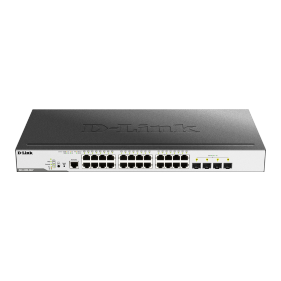
All the switches are equipt with one RJ-45 Console port (a special console cable with a DB9 interface is provided to connect the Switch to a PC) NOTE: For customers interested in D-View, D-Link Corporation's proprietary SNMP management software, go to http://dview.dlink.com.tw/... - Page 12 DGS-3000 Series Layer 2 Managed Gigabit Ethernet Switch Hardware Installation Guide Figure 1-2 Front panel view of the DGS-3000-24TC Figure 1-3 Front panel view of the DGS-3000-26TC...
-
Page 13: Led Indicators
The Switch front panel presents LED indicators for Power, Console, RPS, Fan Err, and Link/Act indicators for all ports including the Gigabit Ethernet ports. Figure 1-4 LED indicators for the DGS-3000-10TC Figure 1-5 LED indicators for the DGS-3000-24TC Figure 1-6 LED indicators for the DGS-3000-26TC... -
Page 14: Rear Panel Description
The rear panel contains an AC power socket, an ON/OFF toggle switch, an outlet for an external redundant power supply or a DC power supply, and security lock. Figure 1-7 Rear panel view of the DGS-3000-10TC Figure 1-8 Rear panel view of the DGS-3000-24TC Figure 1-9 Rear panel view of the DGS-3000-26TC The AC power socket is a standard three-pronged connector that supports the power cord. -
Page 15: Side Panel Description
Figure 1-10 Identical side panels of the DGS-3000-10TC Figure 1-11 Identical side panels of the DGS-3000-24TC Figure 1-12 Identical side panels of the DGS-3000-26TC... -
Page 16: Chapter 2 Installation
• One CD kit for Web UI Reference Guide, CLI Reference Guide, and D-View module If any item is missing or damaged, please contact your local D-Link reseller for replacement. Installation Guidelines Please follow these guidelines for setting up the Switch: •... -
Page 17: Installing The Switch Without A Rack
DGS-3000 Series Layer 2 Managed Gigabit Ethernet Switch Hardware Installation Guide Installing the Switch without a Rack First, attach the rubber feet included with the Switch if installing on a desktop or shelf. Attach these cushioning feet on the bottom at each corner of the device. Allow enough ventilation space between the Switch and any other objects in the vicinity. -
Page 18: Mounting The Switch In A Standard 19" Rack
DGS-3000 Series Layer 2 Managed Gigabit Ethernet Switch Hardware Installation Guide Mounting the Switch in a Standard 19" Rack Figure 2-3 Installing the Switch in a rack Power On (AC Power) 1. Plug one end of the AC power cord into the power socket of the Switch and the other end into the local power source outlet. -
Page 19: Alarm Connector (Dgs-3000-24Tc/26Tc Only)
DGS-3000 Series Layer 2 Managed Gigabit Ethernet Switch Hardware Installation Guide Figure 2-4 Connecting a DC power source to the Switch 1. Make sure that the ON/OFF toggle switch on the rear panel of the Switch is turned off. 2. Connect one end of the DC power cords supplied to a DC power source that will be activated when the AC power is not working. - Page 20 DGS-3000 Series Layer 2 Managed Gigabit Ethernet Switch Hardware Installation Guide Figure 2-5 Alarm Connector The following table describes the alarm connector port pin layout. Contact Description Output. Normal Closed Pin. (42VAC or 60VDC) Output. Common Pin. (42VAC or 60VDC) Output.
-
Page 21: Installing Power Cord Clip
DGS-3000 Series Layer 2 Managed Gigabit Ethernet Switch Hardware Installation Guide Installing Power Cord Clip To prevent accidental removal of the AC power cord, it is recommended to install the power cord clip together with the power cord. 1. With the rough side facing down, insert the Tie Wrap into the hole below the power socket. Figure 2-6 Insert Tie Wrap to the Switch 2. - Page 22 DGS-3000 Series Layer 2 Managed Gigabit Ethernet Switch Hardware Installation Guide 3. Slide the Retainer through the Tie Wrap until the end of the cord. Figure 2-8 Slide the Retainer through the Tie Wrap 4. Circle the tie of the Retainer around the power cord and into the locker of the Retainer. Figure 2-9 Circle around the power cord...
- Page 23 DGS-3000 Series Layer 2 Managed Gigabit Ethernet Switch Hardware Installation Guide 5. Fasten the tie of the Retainer until the power cord is secured. Figure 2-10 Secure the power cord...
-
Page 24: Installing Sfp And Sfp+ Ports
DGS-3000 Series Layer 2 Managed Gigabit Ethernet Switch Hardware Installation Guide Installing SFP and SFP+ Ports The Switch is equipped with SFP (Small Form Factor Portable) and/or SFP+ ports, which are used with fiber-optical transceiver cabling.SFP ports support full-duplex transmissions, auto-negotiation, and can be uplinked with various other switches across a gigabit network. -
Page 25: Connecting The Dps-200 To The Rps Port
DGS-3000 Series Layer 2 Managed Gigabit Ethernet Switch Hardware Installation Guide Connecting the DPS-200 to the RPS Port The DPS-200 redundant power supply can be connected to the RPS port of the Switch using the DC power supply cord, called the DPS-CB150-2PS. It is important to notice that the DPS-200 can supply power to one or two DGS-3000 Series Switches at the same time. -
Page 26: Installing The Rps Into A Rack-Mount Chassis
DGS-3000 Series Layer 2 Managed Gigabit Ethernet Switch Hardware Installation Guide Installing the RPS into a Rack-mount Chassis The DPS-200 is the redundant power supply unit designed to conform to the voltage requirements of the RPS port of the Switch being supported. The DPS-200 can be installed into a DPS-800 and a DPS-900 rack-mount chassis unit. CAUTION: DO NOT connect the RPS to the AC power before the DC power cable is connected. -
Page 27: Dps-900 Rack-Mount Chassis
DGS-3000 Series Layer 2 Managed Gigabit Ethernet Switch Hardware Installation Guide Figure 2-14 Installing the DPS-800 into a rack DPS-900 Rack-mount Chassis The DPS-900 is a standard-size rack-mount (5 standard units in height) designed to hold up to eight DPS-200 redundant power supplies. - Page 28 DGS-3000 Series Layer 2 Managed Gigabit Ethernet Switch Hardware Installation Guide Figure 2-16 Installing the DPS-900 into a rack CAUTION: Installing systems in a rack without the front and side stabilizers installed could cause the rack to tip over, potentially resulting in bodily injury under certain circumstances. Therefore, always install the stabilizers before installing components in the rack.
-
Page 29: Chapter 3 Connecting The Switch
DGS-3000 Series Layer 2 Managed Gigabit Ethernet Switch Hardware Installation Guide Chapter 3 Connecting the Switch Switch to End Node Switch to Switch Connecting To Network Backbone or Server NOTE: All high-performance N-Way Ethernet ports can support both MDI-II and MDI-X connections. Switch to End Node End nodes include PCs outfitted with a 10, 100 or 1000 Mbps RJ-45 Ethernet Network Interface Card (NIC) and routers. -
Page 30: Switch To Switch
DGS-3000 Series Layer 2 Managed Gigabit Ethernet Switch Hardware Installation Guide Switch to Switch There is a great deal of flexibility on how connections are made using the appropriate cabling. • Connect a 10BASE-T switch port to the Switch via a twisted-pair Category 3, 4 or 5 UTP/STP cable. •... -
Page 31: Connecting To Network Backbone Or Server
DGS-3000 Series Layer 2 Managed Gigabit Ethernet Switch Hardware Installation Guide Connecting to Network Backbone or Server The combo SFP ports and the 1000BASE-T ports are ideal for uplinking to a network backbone, server or server farm. The copper ports operate at a speed of 10, 100 or 1000Mbps in full or half duplex mode. The fiber-optic ports can operate at both 100Mbps and 1000Mbps in full duplex mode. -
Page 32: Chapter 4 Introduction To Switch Management
DGS-3000 Series Layer 2 Managed Gigabit Ethernet Switch Hardware Installation Guide Chapter 4 Introduction to Switch Management Management Options Connecting the Console Port First Time Connecting to the Switch Password Protection IP Address Assignment SNMP Settings Management Options This system may be managed out-of-band through the console port on the front panel or in-band using Telnet. The user may also choose the Web-based management, accessible through a Web browser. - Page 33 DGS-3000 Series Layer 2 Managed Gigabit Ethernet Switch Hardware Installation Guide • Select Terminal keys for Function, Arrow and Ctrl keys. Make sure to use Terminal keys (not Windows keys) are selected. NOTE: When using HyperTerminal with the Microsoft® Windows® 2000 operating system, ensure that Windows 2000 Service Pack 2 or later is installed.
-
Page 34: First Time Connecting To The Switch
DGS-3000-26TC Gigabit Ethernet Switch Command Line Interface Firmware: Build 1.10.008 Copyright(C) 2014 D-Link Corporation. All rights reserved. UserName: Figure 4-2 Initial screen, first time connecting to the Switch Press Enter in both the Username and Password fields. Then access will be given to enter commands after the command prompt DGS-3000-26TC:admin# There is no initial username or password. -
Page 35: Ip Address Assignment
DGS-3000 Series Layer 2 Managed Gigabit Ethernet Switch Hardware Installation Guide IP Address Assignment An IP address must be assigned to each switch, which is used for communication with an SNMP network manager or other TCP/IP application (for example BOOTP, TFTP). The Switch's default IP address is 10.90.90.90. The user may change the default Switch IP address to meet the specification of your networking address scheme. -
Page 36: Traps
DGS-3000 Series Layer 2 Managed Gigabit Ethernet Switch Hardware Installation Guide Traps Traps are messages that alert network personnel of events that occur on the Switch. The events can be as serious as a reboot (someone accidentally turned OFF the Switch), or less serious like a port status change. The Switch generates traps and sends them to the trap recipient (or network manager). -
Page 37: Chapter 5 Web-Based Switch Configuration
DGS-3000 Series Layer 2 Managed Gigabit Ethernet Switch Hardware Installation Guide Chapter 5 Web-based Switch Configuration Introduction Logging onto the Web Manager Web-based User Interface Web Pages Introduction Most software functions of the Switch can be managed, configured, and monitored via the embedded Web-based (HTML) interface. -
Page 38: Web-Based User Interface
Select the menu or window to display. Open folders and click the hyperlinked menu buttons and Area 1 subfolders contained within them to display menus. Click the D-Link logo to go to the D-Link website. Presents a graphical near real-time image of the front panel of the Switch. This area displays the Area 2 Switch's ports, console and management port, showing port activity. -
Page 39: Web Pages
DGS-3000 Series Layer 2 Managed Gigabit Ethernet Switch Hardware Installation Guide Web Pages When connecting to the management mode of the Switch with a Web browser, a login screen is displayed. There is no default user name or password necessary to access the Switch's management mode. NOTE: Be sure to configure the user name and password in the User Accounts window before connecting the Switch to the greater network. -
Page 40: Appendix Section
UTP Cat.5, Cat. 5 Enhanced for 100BASE-TX UTP Cat.3, 4, 5 for 10BASE-T EIA/TIA-568 100-ohm screened twisted-pair (STP)(100m) Number of Ports DGS-3000-10TC: Eight Copper ports (10/100/1000Mbps), Two Combo Copper/SFP ports (10/100/1000Mbps and 100/1000Mbps). DGS-3000-24TC: Twenty Copper ports (10/100/1000Mbps), Four Combo Copper/SFP ports (10/100/1000Mbps and 100/1000Mbps). -
Page 41: Performance
Operation: 10% to 90% RH non-condensing Storage: 5% to 90% RH non-condensing Dimensions DGS-3000-10TC: 228.5mm (W) x 195mm (D) x 44mm (H) DGS-3000-24TC: 440mm (W) x 209.9mm (D) x 44mm (H) DGS-3000-26TC: 440mm (W) x 209.9mm (D) x 44mm (H) Weight DGS-3000-10TC: 1.1 kg... - Page 42 DGS-3000 Series Layer 2 Managed Gigabit Ethernet Switch Hardware Installation Guide Green Solid Light RPS is connected and the RPS switch is turned on. Light off RPS is not connected or the RPS switch is turned off. Fan Err Blinking When any of the fans has failed.
-
Page 43: Port Functions
DGS-3000 Series Layer 2 Managed Gigabit Ethernet Switch Hardware Installation Guide Port Functions Feature Detailed Description Console Port RJ-45 interface for Out-Of-Band (OOB) CLI configuration. Copper Ports Compliant with the following standards: • IEEE 802.3 compliance • IEEE 802.3u compliance •... - Page 44 DGS-3000 Series Layer 2 Managed Gigabit Ethernet Switch Hardware Installation Guide • DEM-315GT (1000BASE-ZX, Single-mode, 80km) • DEM-302S-LX (1000BASE-LX, Single-mode, 2km) WDM transceivers supported: • DEM-330T (1000BASE-BX, TX-1550/RX-1310nm, Single-mode, 10km) • DEM-330R (1000BASE-BX, TX-1310/RX-1550nm, Single-mode, 10km) • DEM-331T (1000BASE-BX, TX-1550/RX-1310nm, Single-mode, 40km) •...
-
Page 45: Appendix B - Cables And Connectors
DGS-3000 Series Layer 2 Managed Gigabit Ethernet Switch Hardware Installation Guide Appendix B – Cables and Connectors Ethernet Cable When connecting the Switch to another switch, a bridge or hub, a normal cable is necessary. Please review these products for matching cable pin assignment. The following diagrams and tables show the standard RJ-45 receptacle/connector and their pin assignments. -
Page 46: Console Cable
DGS-3000 Series Layer 2 Managed Gigabit Ethernet Switch Hardware Installation Guide Console Cable When connecting the Switch a PC, a Console cable is necessary. The following diagrams and tables show the standard Console-to-DJ-45 receptacle/connector and their pin assignments. Figure B- 2. Console-to-RJ-45 Cable Console-RJ-45 Pin Assignments Console (DB9/RS232) RJ-45... -
Page 47: Redundant Power Supply (Rps) Cable
DGS-3000 Series Layer 2 Managed Gigabit Ethernet Switch Hardware Installation Guide Redundant Power Supply (RPS) Cable When connecting the Switch to a Redundant Power Supply, an RPS cable is necessary. Please review these products for matching cable pin assignment.The following diagrams and tables show the DPS-CB150-2PS receptacle/connector and their pin assignments. -
Page 48: Warranties & Technical Support
The customer must submit with the product as part of the claim a written description of the Hardware defect or Software nonconformance in sufficient detail to allow D-Link to confirm the same, along with proof of purchase of the product (such as a copy of the dated purchase invoice for the product) if the product is not registered. - Page 49 D-Link Corporation/D-Link Systems, Inc., as stipulated by the United States Copyright Act of 1976 and any amendments thereto. Contents are subject to change without prior notice. Copyright 2004 by D-Link Corporation/D-Link Systems, Inc.
-
Page 50: Product Registration
Product Registration Register your D-Link product online at http://support.dlink.com/register/ Product registration is entirely voluntary and failure to complete or return this form will not diminish your warranty rights. -
Page 51: Tech Support
You can find software updates and user documentation on the D- Link website. D-Link provides free technical support for customers within the United States and within Canada for the duration of the service period, and warranty confirmation service, during the warranty period on this product. -
Page 52: Technical Support
Technical Support United Kingdom (Mon-Fri) Home Wireless/Broadband 0871 873 3000 (9.00am–06.00pm, Sat 10.00am-02.00pm) Managed, Smart, & Wireless Switches, or Firewalls 0871 873 0909 (09.00am – 05.30pm) (BT 10ppm, other carriers may vary.) Ireland (Mon-Fri) All Products 1890 886 899 (09.00am-06.00pm, Sat 10.00am-02.00pm) €0.05ppm peak, €0.045ppm off peak Times Internet http://www.dlink.com... -
Page 53: Assistance Technique
Assistance technique Assistance technique D-Link sur internet : http://www.dlink.com Assistance technique D-Link par téléphone : 01 76 54 84 17 Du lundi au vendredi de 9h à 19h (hors jours fériés) Asistencia Técnica Asistencia Técnica Telefónica de D-Link: +34 902 30 45 45 0,067 €/min... - Page 54 Pomoc techniczna Telefoniczna pomoc techniczna firmy D-Link: 0 801 022 021 Pomoc techniczna firmy D-Link świadczona przez Internet: http://www.dlink.com Technická podpora Web: http://www.dlink.com E-mail: support@dlink.cz Telefon ČR: +420 211 151 640 nebo SK: +421 (0)692 147 110 Telefonická podpora je v provozu: PO - PÁ od 09:00 do 17:00 Volání...
- Page 55 Internetin kautta : http://www.dlink.com Arkisin klo. 09:00 - 18: 00 Numerosta : 0200-555 57 Teknisk Support D-Link Teknisk Support via Internet: http://www.dlink.com D-Link Teknisk Support via telefon: 0770-33 00 35 Vardagar 08:00 - 17:00 Assistência Técnica Assistência Técnica da D-Link na Internet: http://www.dlink.com e-mail: soporte@dlink.es...
- Page 56 D-Link - ovo spletno stran www.dlink.eu http://www.dlink.com Suport tehnic Vă mulţumim pentru alegerea produselor D-Link. Pentru mai multe informaţii, suport şi manuale ale produselor vă rugăm să vizitaţi site-ul D-Link www.dlink.eu http://www.dlink.com...
- Page 57 Technical Support You can find software updates and user documentation on the D-Link website. Tech Support for customers in Australia: D-Link Middle East - Dubai, U.A.E. Tel: 1300-766-868 Plot No. S31102, 24/7 Technical Support Jebel Ali Free Zone South, Web: http://www.dlink.com.au P.O.Box 18224, Dubai, U.A.E.
- Page 58 Technical Support You can find software updates and user documentation on the D-Link website. Tech Support for customers in Iran Israel המגשימים רח Unit 5, 5th Floor, No. 20, 17th Alley , Bokharest ת " פ קרית מטלון St. , Argentine Sq. , 49348 .
- Page 59 Техническая поддержка Обновления программного обеспечения и документация доступны на Интернет-сайте D-Link. D-Link предоставляет бесплатную поддержку для клиентов в течение гарантийного срока. Клиенты могут обратиться в группу технической поддержки D-Link по телефону или через Интернет. Техническая поддержка D-Link: 8-800-700-5465 Техническая поддержка через Интернет: http://www.dlink.ru...
- Page 60 SOPORTE TÉCNICO Usted puede encontrar actualizaciones de softwares o firmwares y documentación para usuarios a través de nuestro sitio www.dlinkla.com SOPORTE TÉCNICO PARA USUARIOS EN LATINO AMERICA Soporte técnico a través de los siguientes teléfonos de D-Link PAIS NUMERO Argentina...
- Page 61 Suporte Técnico Caso tenha dúvidas na instalação do produto, entre em contato com o Suporte Técnico D-Link. Acesse o site: www.dlink.com.br/suporte...
- Page 62 D-Link 友訊科技 台灣分公司 技術支援資訊 如果您還有任何本使用手冊無法協助您解決的產品相關問題,台灣 地區用戶可以透過我們的網站、電子郵件或電話等方式與D-Link台灣 地區技術支援工程師聯絡。 D-Link 免付費技術諮詢專線 0800-002-615 手機付費電話 (02)6600-0123#8715 服務時間:週一至週五,早上9:00到晚上9:00 (不含周六、日及國定假日) 網 站:http://www.dlink.com.tw 電子郵件:dssqa_service@dlink.com.tw 如果您是台灣地區以外的用戶,請參考D-Link網站全球各地 分公司的聯絡資訊以取得相關支援服務。 產品保固期限、台灣區維修據點查詢,請參考以下網頁說明: http://www.dlink.com.tw 產品維修: 使用者可直接送至全省聯強直營維修站或請洽您的原購買經銷商。...
- Page 63 Dukungan Teknis Update perangkat lunak dan dokumentasi pengguna dapat diperoleh pada situs web D-Link. Dukungan Teknis untuk pelanggan: Dukungan Teknis D-Link melalui telepon: Tel: +62-21-5731610 Dukungan Teknis D-Link melalui Internet: Email : support@dlink.co.id Website : http://support.dlink.co.id...
- Page 64 Technical Support この度は弊社製品をお買い上げいただき、誠にあり がとうございます。 製品に同梱されている保証書の購入元にお問い合 わせください。...
- Page 65 技术支持 辦公地址:北京市朝陽區將台路5號院5號樓 郵編:100016 技術支持中心電話:400-629-6688 技術支持中心傳真:(028)-61317620 各地維修中心地址請登陸官方網站查詢 網址:http://www.dlink.com.cn 400電話工作時間:工作日9:00-19:00;節假日9:00-18:00.
-
Page 66: Registration Card
8. What category best describes your company? Aerospace Engineering Education Finance Hospital Legal Insurance/Real Estate Manufacturing Retail/Chain store/Wholesale Government Transportation/Utilities/Communication System house/company Other________________________________ 9. Would you recommend your D-Link product to a friend? Don't know yet 10.Your comments on this product? __________________________________________________________________________________________ __________________________________________________________________________________________...