Dell Networking N4032 Getting Started Manual
Networking n4000 series switch
Hide thumbs
Also See for Networking N4032:
- Configuration manual (60 pages) ,
- Getting started manual (378 pages) ,
- Reference manual (17 pages)

Related Manuals for Dell Networking N4032


Summary of Contents for Dell Networking N4032
-
Page 1: Getting Started Guide
Dell Networking N4000 Series Switch Getting Started Guide Regulatory Model: N4032, N4032F, N4064, N4064F... - Page 3 Dell Networking N4000 Series Switch Getting Started Guide Regulatory Model: N4032, N4032F, N4064, N4064F...
-
Page 4: Notes And Cautions
Other trademarks and trade names may be used in this publication to refer to either the entities claiming the marks and names or their products. Dell Inc. disclaims any proprietary interest in trademarks and trade names other than its own. -
Page 5: Table Of Contents
....Rack Mounting Safety Considerations ..Installing the Dell ReadyRails System ..Installing the Switch . - Page 6 Starting and Configuring the Switch . . . Connecting a Switch to a Terminal ... Booting the Switch ....Performing the Initial Configuration .
-
Page 7: Introduction
For information about how to configure and monitor switch features, see the User’s Configuration Guide, which is available on the Dell Support website at dell.com/support for the latest updates on documentation and firmware. -
Page 8: Hardware Overview
Dell designed the N4000 Series for energy savings from the power cord to the ports, starting with EEE-capable ports to reduce active and passive port power consumption for all ports. In addition to redundant power supplies that can operate efficiently in all modes, variable speed fans reduce consumption by adjusting their speed for their environment through multiple temperature monitors. -
Page 9: Front Panel
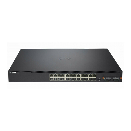
• The fan is removable and can be managed • Standard 1U chassis high Front Panel The following image shows the Dell Networking N4000 front panel: Figure 1. Dell Networking N4000 Front Panel QSFP+ Ports The front panel includes: •... -
Page 10: Quad-Port Sfp Uplink Fixed Ports
The QSFP connections can be used for stacking. Stacking is supported at distances of up to 100M. NOTE: The QSFP modules can be used only for the Dell Networking N4000-series switches. Expansion Slot The 80 Gbps expansion slot supports the following modules: •... -
Page 11: Uart Interface
UART Interface The UART (Universal Asynchronous Receiver Transmitter) port is modeled after the industry standard 16550 UART devices. The UART port provides serial communication capabilities, which allows communication with the model or other external devices using RS-232 protocol. A serial port provides a direct connection to the switch and allows you to access the CLI from a console terminal connected to the port through the provided serial cable (with RJ45 YOST to female DB-9 connectors). -
Page 12: System Leds
System LEDs The system contains light emitting diodes (LEDs) that provide indications about the System, Temp, Diag, Fan, Stack, and Locator status of the Dell Networking N4000 switch. Table 1 contains the status LED definitions: Table 1. LED Definitions for System... -
Page 13: Locator Led
Table 1. LED Definitions for System (Continued) Feature Detailed Description Comment Locator LED On back panel • Blinking blue - Locator function is enabled • Solid blue - Locator function is disabled The thermal sensors system temperature threshold is 75°C. When the threshold is exceeded, the Temp LED lights up to Red. -
Page 14: Installation
Installation Site Preparation Before installing the switch or switches, make sure that the chosen installation location meets the following site requirements: • Clearance—There is adequate front and rear clearance for operator access. Allow clearance for cabling, power connections, and ventilation. •... -
Page 15: Unpacking Steps
You may either place the switch on the rack shelf or mount the switch directly into a 19" wide, EIA-310-E compliant rack (four-post, two-post, or threaded methods). The Dell ReadyRails™ system is provided for 1U front-rack, and two-post installations. The ReadyRails system includes two separately packaged rail assemblies and two rails that are shipped attached to the sides of the switch. -
Page 16: Rack Mounting Safety Considerations
Rack Mounting Safety Considerations • Rack loading—Overloading or uneven loading of racks may result in shelf or rack failure, causing damage to equipment and possible personal injury. Stabilize racks in a permanent location before loading begins. Mount components beginning at the bottom of the rack, then work to the top. Do not exceed your rack load rating. -
Page 17: Installing The Dell Readyrails System
Installing the Dell ReadyRails System The ReadyRails rack mounting system is provided to easily configure your rack for installation of your switch. The ReadyRails system can be installed using the 1U tool-less method or one of three possible 1U tooled methods (two-post flush mount, two-post center mount, or four-post threaded). - Page 18 Two-post Flush-mount Configuration 1 For this configuration, the castings must be removed from the front side of each ReadyRails assembly. See Figure 4, item 1 on page 16. Use a Torx™ driver to remove the two screws from each front flange ear (on the switch side of the rail) and remove each casting.
- Page 19 3 Slide the plunger bracket forward against the vertical post and secure the plunger bracket to the post flange with two user-supplied screws. See Figure 4, item 3. 4 Repeat this procedure for the second rail. Two-post Center-mount Configuration 1 Slide the plunger bracket rearward until it clicks into place and secure the bracket to the front post flange with two user-supplied screws.
-
Page 20: Installing The Switch
2 For each rail, attach the front and rear flanges to the post flanges with two user-supplied screws at each end. See Figure 6, item 2 on page 18. Figure 6. Four-post Threaded Configuration Installing the Switch The switch may be mounted in the 1U front-rack and 1U two-post (flush and center) configurations. - Page 21 1U Front-rack Installation The rails that are attached to the switch must be configured. 1 Attach the switch rails (inner chassis members) to the N4000 switch. Figure 7, item 1 shows the detail for the front standoff with locking tab. Figure 7.
-
Page 22: Starting And Configuring The Switch
Starting and Configuring the Switch The following flow chart provides an overview of the steps you use to perform the initial configuration after the switch is unpacked and mounted. Figure 8. Installation and Configuration Flow Chart Connect Power and Console Power On Enter Boot Menu? -
Page 23: Connecting A Switch To A Terminal
® the setting is for Terminal keys (not Microsoft Windows keys). 3 Connect the RJ45 connector on the cable directly to the Dell Networking N4000 RJ45 console port located on the back of the switch. Starting and Configuring the Switch... -
Page 24: Booting The Switch
The N4000 Series switch booted successfully. • The console connection was established, and the Dell Easy Setup Wizard prompt appears on the screen of a VT100 terminal or terminal equivalent. The initial switch configuration is performed through the console port. After the initial configuration, you can manage the switch from the already- connected console port or through a remote connection. -
Page 25: Initial Configuration Procedure
Telnet (Telnet client) or HTTP (Web browser). Initial Configuration Procedure You can perform the initial configuration by using the Dell Easy Setup Wizard or by using the CLI. The wizard automatically starts when the switch configuration file is empty. You can exit the wizard at any point by entering [ctrl+z], but all configuration settings specified will be discarded, and the switch will use the default values. -
Page 26: Example Session
Help text is in parentheses. The following example contains the sequence of prompts and responses associated with running an example Dell Easy Setup Wizard session, using the input values listed above. After the switch completes the POST and is booted, the following text is displayed: (Unit 1-Waiting to select management unit)>... - Page 27 The system is not setup for SNMP management by default. To manage the switch using SNMP (required for Dell Network Manager) you can Set up the initial SNMP version 2 account now. Return later and setup other SNMP accounts. (For more information on setting up an SNMP version 1 or 3 account, see the user documentation).
- Page 28 If the information is incorrect, enter (N) to discard the configuration and restart the wizard: [Y/N] y Thank you for using the Dell Easy Set up Wizard. You will now enter CLI mode. Applying Interface configuration, please wait...
-
Page 29: Next Steps
IP address into a Telnet or SSH client. Alternatively, you can continue to use the console port for local CLI access to the switch. Your Dell Networking N4000 switch supports basic switching features such as VLANs, 802.1X, RADIUS and TACACS+. - Page 30 Starting and Configuring the Switch...
- Page 31 بدء تشغيل المحول وتهيئته...
- Page 32 في عميلOOBالخاص بواجهة إدارةIP ، قم بإدخال عنوانCLI اإلدارة عن ب ُعد في الوصع . وبدال ً من ذلك، يمكنك متابعة استخدام منفذ وحدة التحكم للوصول لوضعSSH أوTelnet . المحلي بالمحولCLI يدعن ميزات التبديل األساسية مثلDell Networking N4000 كما أن محول .TACACS+ وRADIUS1.208 وX وVLANs بدء تشغيل المحول وتهيئته...
- Page 33 If the information is incorrect, enter (N) to discard the configuration and restart the wizard: [Y/N] y Thank you for using the Dell Easy Set up Wizard. You will now enter CLI mode. Applying Interface configuration, please wait...
- Page 34 First: Step 1: The system is not setup for SNMP management by default. To manage the switch using SNMP (required for Dell Network Manager) you can Set up the initial SNMP version 2 account now. Return later and setup other SNMP accounts. (For more information on setting up an SNMP version 1 or 3 account, see the user documentation).
- Page 35 .ويكون نص التعليمات بين األقواس كما يحتوي المثال التالي على طلبات متسلسلة وردود مرتبطة بتشغيل جلسة مثل جلسة .، باستخدام قيم اإلدخال المدرجة أعالهDell Easy Setup Wizard : ويتم تمهيد التشغيل، سيتم عرض النص التاليPOST بعدما يقوم المحول بإنهاء اختبار...
- Page 36 إجراء التهيئة األولية .CLI أو استخدامDell Easy Setup Wizard يمكن إجراء التهيئة األولية باستخدام يبدأ تشغيل المعالج تلقائيا ً عندما يكون ملف تهيئة المحول فارغا ً . كما يمكنك إنهاء المعالج ]، ولكن سيتم تجاهل جميع إعدادات التهيئةctrl+z[ في أي مرحلة عن طريق الضغط على...
- Page 37 • . بنجاحN4000 Series وتم تمهيد تشغيل المحول • علىDell Easy Setup Wizard كما تم إنشاء توصيل وحدة التحكم، ويظهر طلب • . الطرفية أو محطة طرفية متكافئةVT100 شاشة محطة ،إن إجراء التهيئة األولية للمحول تكون من خالل منفذ وحدة التحكم. وبعد اكتمال التهيئة األولية...
- Page 38 .بعد االنتهاء من جميع التوصيالت الخارجية، قم بتوصيل محطة طرفية بأحد المحوالت لتهيئة المحول :مالحظة اقرأ مالحظات اإلصدار لهذا المنتج قبل المتابعة. يمكنك تنزيل مالحظات اإلصدار .dell.com/support على اإلنترنت على العنوان التاليDell من موقع دعم :مالحظة نوصيك بالحصول على أحدث إصدار من مستندات المستخدم من على موقع دعم...
- Page 39 بدء تشغيل المحول وتهيئته الرسم البياني التالي يقدم نظرة عامة حول الخطوات التي ستقوم بها ألداء عملية التهيئة األولية .بعد فك المحول وتركيبه جدول تسلسل التركيب والتهيئة شلل ����� ������ توصيل التيار الكهربائي ��������� ����� ووحدة التحكم ����� تشغيل نعم بدء...
- Page 40 1 األماميU تركيب حامل .يجب تهيئة القضبان التي يتم تركيبها للمحول . شكل 7، يعرضN4000 قم بتركيب قضبان المحول (مكونات الهيكل الداخلي) بمحول .العنصر 1 تفاصيل األسنان البارزة األمامية مع لسان التثبيت تركيب قضبان المحول شلل بعد تركيب قصيبي المحول، قم بمحاذاتهم مع القضبان الجاهزة التي تم تركيبها سابقا ً على الحامل...
- Page 41 screws from each flange ear and remove each casting (Figure 2.4, item 1). Retain castings for future rack requirements. بالنسبة لكل قضيب، قم بتركيب الدعامات األمامية والخلفية بحواف العمود باستخدام For each rail, attach the front and rear flanges to the post flanges with two مسمارين...
- Page 42 قم بدفع دعامة الكابس إلى األمام باتجاه العمود الرأسي ثم قم بتأمين دعامة الكابس لدعامة .3 العمود باستخدام مسمارين متوفرين لدى المستخدم. انظر شكل 4، العنصر .كرر هذا اإلجراء للقضيب الثاني Two-post Center-mount Configuration Slide the plunger bracket rearward until it clicks into place and secure the تهيئة...
- Page 43 تهيئة تركيب أعمدة ثنائية على التوازي بالنسبة لهذه التهيئة، يجب إزالة القوالب من الجانب األمامي من كل مجموعة إلزالةTorx™ . انظر شكل 4، العنصر 1 في الصفحة 44. استخدم مفكReadyRails .مسمارين من كل دعامة جانبية أمامية (في جانب المحول للقضيب) وإزالة كل قالب االحتفاظ...
- Page 44 Dell ReadyRails تركيب نظام لتسهيل تهيئة الحامل لتركيب المحول الخاصReadyRails يتم توفير نظام تركيب الحامل 1 مع أدوات أقل أو أحد الطرقU باستخدام طريقةReadyRails بك. ويمكن تركيب النظام 1 المزودة بالمعدات (تركيب أعمدة ثنائية على التوازي أو تركيب أعمدةU الثالث الممكنة...
- Page 45 اعتبارات سالمة الحامل التحميل الزائد على الحامل أو التحميل غير المتكافئ على الحوامل يؤدي إلى كسر الحامل • أو الرف، مما يتسبب في إلحاق الضرر بالمعدات واحتمال إصابة األشخاص. يجب تثبيت .الحوامل في موقع دائم قبل بدء التحميل. تبدأ مكونات التركيب من أسفل الحامل ثم إلى أعلى .يجب...
- Page 46 19 كما يمكنك وضع المحول أيضا ً على الحامل أو تركيب المحول مباشرة على مساحة تبلغ متوافق (أعمدة رباعية أو أعمدة ثنائية وسائل مترابطة). إن نظامEIA-310-E بوصه، حامل ReadyRails 1 األمامي وتركيب قاعدتين. نظامU متوفر للحاملDell ReadyRails™ .يشتمل على حزمتين منفصلتين من وحدات القضبان وقضيبان يتم شحنهم مرفقين بجانبي المحول...
- Page 47 التركيب إعداد الموقع قبل تركيب المحول أو المحوالت، تأكد من أن موقع التركيب الذي تم اختياره يفي بمتطلبات :الموقع التالية المسافة الفاصلة - يجب أن تتوفر هناك مسافة فاصلة مالئمة أمامية وخلفية للوصول إلى • .المشغل. السماح بوجود مسافة فاصلة للكابل ووصالت اإلمداد بالطاقة والتهوية الكابالت...
- Page 48 للمنافذLED مصابيح شلل 1 ﺍﻟﻤﺮﻭﺣﺔ ﻣ ُﺤﺪﺩ ﺍﻟﻤﻮﻗﻊ ﻭﺣﺪﺓ ﺍﻟﺘﺤﻜﻢ ﺣﺰﻣﺔ ﺩﺭﺟﺔ ﺍﻟﺤﺮﺍﺭﺓ للنظامLED مصباح نظرة عامة حول األجهزة...
- Page 49 للنظامLED مصابيح ) والتي تشير إلى حالة النظامLED يحتوي النظام على صمام ثنائي باعث للضوء (مصابيح .Dell Networking N4000 ودرجةالحرارة والفحص والمروحة والحزمة ومحدد الموقع لمحول :LED كما جدول 1 يحتوي على تعريفات حالة مصابيح للنظامLED تعريفات مصباح...
- Page 50 UART واجهة UART 16550 (إرسال واستقبال شامل غير متزامن) تم تصميمه بعد أجهزةUART إن منفذ قدرات اتصال تسلسلية، مما يتيح االتصالUART التي تتمتع بمعيار الصناعة. يوفر منفذ . كما أن المنفذ التسلسلي يوفرRS-232 بالمنتج أو أجهزة خارجية أخرى باستخدام بروتوكول ...
- Page 51 لإلشارة إلى حالة منفذ اللوحة األماميةLED مصابيح • . للتجميع. إن التجميع يدعم مسافات تصل إلى 001 مQSFP يمكن استخدام توصيالت :مالحظة . فقطDell Networking N4000-series لمحوالتQSFP يمكن استخدام طرز فتحات التوسيع :تدعم فتحات التوسيع 08 جيجابايت/الثانية الطرز التالية )10G (أربعة منافذSFP+ •...
- Page 52 المروحة قابلة لإلزالة ويمكن التحكم بها • 1 ذو معيار عاليU هيكل • اللوحة األمامية :Dell Networking N4000 الصورة التالية تعرض اللوحة األمامية اللوحة األماميةDell Networking N4000 شلل QSFP+ Ports :اللوحة األمامية تتضمن 01 الثابتةG Base-T + أوSFP 84/42 منافذ...
- Page 53 لتوفير الطاقة من منفذ الطاقة إلى المنافذ والبدءN4000 Series بتصميمDell قامت شركة ممك ّ نه لتقليل استهالك طاقة المنفذ الخامل والنشط بالنسبة لجميع المنافذ. باإلضافةEEE بمنافذ إلى إمدادات الطاقة المتكررة التي يمكنها تشغيلها بكفاءة في جميع األوضاع، وسرعات المراوح...
- Page 54 Networking N4000 Series: يقدم هذا المستند معلومات أساسية حول محوالت ® ، كما يتضمن كيفية تثبيت محول وإجراء التهيئةN4064F ،N4064 ،N4032F ،N4032 ،األولية. للحصول على المزيد من المعلومات حول كيفية التهيئة وميزات محول الرصد الرجاء االطالع على دليل التهيئة للمستخدم ، والمتوفر على موقع الدعم للشركة على الويب...
- Page 55 48 ....... بدء تشغيل المحول وتهيئته 49 ........توصيل محول بالمحطة الطرفية 50 ............تمهيد تشغيل المحول 50 ........... إجراء التهيئة األولية 51 ..........إجراء التهيئة األولية 52 ............جلسة مثال 55 ...........الخطوات التالية المحتويات...
- Page 56 38 .......... للنظامLED مصابيح 40 ............التركيب 40 .............إعداد الموقع 40 ............... فك المحول 40 ..........محتويات الحزمة 41 ............خطوات الفك 41 ..........تركيب المحول على حامل 42 ..........اعتبارات سالمة الحامل 43 ......Dell ReadyRails تركيب نظام 46 ............تركيب المحول المحتويات...
- Page 57 .المعلومات الواردة في هذا المنشور عرضة للتغيير دون إشعار . 3102 ©. جميع الحقوق محفوظةDell Inc .Dell Inc ي ُمنع تماما ً إجراء أية عملية نسخ بأي شكل من األشكال لهذه المواد دون الحصول على إذن خطي من شركة ReadyRails™ وOpenManage™ ، وDELL ، وشعارDell العالمات...
- Page 58 الشبكاتDell المحولN4000 Series دليل بدء التشغيل ،N4032F ،N4032 الطراز التنظيمي N4064F ،N4064...
- Page 60 Printed in Poland w w w. d el l .c om | d el l .c om / s up p or t...