Motorola DCT 2000 Installation Manual
Digital consumer terminal
Hide thumbs
Also See for DCT 2000:
- Operation manual (187 pages) ,
- User manual (124 pages) ,
- Owner's manual (44 pages)
Table of Contents
Advertisement
Quick Links
Download this manual
See also:
Owner's Manual
Advertisement
Table of Contents

Related Manuals for Motorola DCT 2000


Summary of Contents for Motorola DCT 2000
- Page 1 D C T 2 0 0 0 D i g i t a l C o n s u m e r T e r m i n a l I n s t a l l a t i o n M a n u a l MESSAGES REMOTE CURSOR...
- Page 2 Declaration of Conformity: According to 47 CFR, Parts 2 and 15 for Class B Personal Computers and Peripherals; and/or CPU Boards and Power Supplies used with Class B Personal Computers, Motorola, Inc., 6450 Sequence Drive, San Diego, CA 92121, 1-800-225-9446, declares under sole responsibility that the product identifies with 47 CFR Part 2 and 15 of the FCC Rules as a Class B digital device.
- Page 3 Motorola, Inc. Motorola reserves the right to revise this publication and to make changes in content from time to time without obligation on the part of Motorola to provide notification of such revision or change. Motorola provides this guide without warranty of any kind, either implied or expressed, including, but not limited to, the implied warranties of merchantability and fitness for a particular purpose.
-
Page 4: Table Of Contents
C o n t e n t s S e c t i o n 1 I n t r o d u c t i o n Features, Options, and Interfaces........................1-1 Using This Manual ............................1-2 Related Documentation..........................1-3 Document Conventions..........................1-3 If You Need Help ............................1-4 Calling for Repairs ............................1-4 S e c t i o n 2... - Page 5 C o n t e n t s S e c t i o n 4 A d d i n g t h e I R B l a s t e r O p t i o n Locating the IR Receiver on the VCR......................4-1 Installing the IR Blaster ..........................4-2 Checking the Installation ..........................4-2...
- Page 6 C o n t e n t s i i i Parental Control - LED and OSD ..................B-20 Mute Status ........................B-20 Current Channel Status - OSD ..................B-20 Current Channel Status − OSD fields ................B-22 d 08: Renewable Security System ......................B-23 TVPC Required −...
- Page 7 C o n t e n t s Figure 3-7 A/B In module with return on Cable A ..................3-7 Figure 3-8 A/B In module with return on Cable B ..................3-8 Figure 3-9 Return on STARFONE module ....................3-9 Figure 3-10 Return on Cable A........................3-10 Figure 3-11 Return on Cable B........................
- Page 8 C o n t e n t s Figure B-25 Mac Frequency Table - OSD ....................B-36 Figure B-26 Message Types - OSD ......................B-36 Figure B-27 In Band PAT - OSD ....................... B-36 Figure B-28 In Band PMT – OSD ......................B-37 Figure B-29 Task Status - OSD ........................
- Page 9 C o n t e n t s T a b l e s Table 2-1 Front panel ..........................2-2 Table 2-2 Rear panel ...........................2-3 Table 2-3 Options ............................2-5 Table 2-4 Remote control keys ........................2-8 Table 3-1 Audio port functionality ......................3-16 Table 3-2 Operational check ........................
-
Page 10: I N T R O D U C T I O N
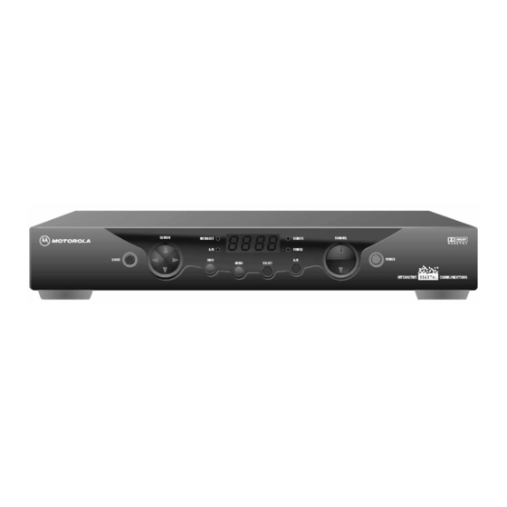
Section 1 I n t r o d u c t i o n The Motorola DCT2000 is an analog/digital terminal designed to support 64 and 256 QAM digital signal formats, and it can be configured to support analog descrambling. -
Page 11: Using This Manual
1 - 2 I n t r o d u c t i o n Figure 1-1 illustrates front and rear views of the DCT2000: F i g u r e 1 - 1 D C T 2 0 0 0 a d v a n c e d s e t - t o p t e r m i n a l CURSOR CHANNEL MESSAGES... -
Page 12: Related Documentation
I n t r o d u c t i o n 1 - 3 R e l a t e d D o c u m e n t a t i o n Separate instruction manuals are available for associated components. Although these may be useful, they are not necessary to install or operate the basic DCT2000: DCT2000 User Guide DCT 1000 Cable Terminal Installation Manual... -
Page 13: If You Need Help
C a l l i n g f o r R e p a i r s If repair is necessary, call the Motorola Repair Facility at 1-800-227-0450 for a Return for Service Authorization (RSA) number before sending the unit. The RSA number must be prominently displayed on all equipment cartons. -
Page 14: O V E R V I E W
Section 2 O v e r v i e w The DCT2000 uses state-of-the-art digital compression technology to provide new revenue generating services. The DCT2000 can be configured to support real time reverse path communications, providing a gateway to interactive services such as Video on Demand (VOD), Internet access, Email, home shopping, and more. - Page 15 2 - 2 O v e r v i e w Table 2-1 describes the front-panel controls and LEDs: T a b l e 2 - 1 F r o n t p a n e l Feature Function Lights if optional switch is activated Lights to indicate that a message is present MESSAGES Normally displays current channel number or time of day;...
-
Page 16: Rear Panel
O v e r v i e w 2 - 3 R e a r P a n e l Figure 2-2 illustrates the rear panel of the DCT2000, which contains a switched power outlet; connectors for video, audio, and RF cabling; data output connectors; and IR Blaster output connector: F i g u r e 2 - 2 D C T 2 0 0 0 r e a r p a n e l... - Page 17 2 - 4 O v e r v i e w Item Function Left and right audio RCA jacks used for stereo audio output AUDIO OUT V IDEO RCA jack used to connect the DCT2000 to a composite (baseband) video TV or a monitor; in some configurations this jack connects to a TV Pass Card Cover for an area reserved for future use Optical...
-
Page 18: Options
O v e r v i e w 2 - 5 O p t i o n s The DCT2000 supports a variety of options enabling your company to offer a system tailored to the individual needs of your subscribers. Figure 2-3 illustrates the options available for the DCT2000: F i g u r e 2 - 3 D C T 2 0 0 0 o p t i o n s... - Page 19 2 - 6 O v e r v i e w O ption Name F un ct i o n Used in a dual cable system; enables the cable signal Dual A/B on the current side (A or B) to go directly to a TV or RF Bypass RF OUT STARFONE...
-
Page 20: Remote Controls
O v e r v i e w 2 - 7 R e m o t e C o n t r o l s The basic DCT2000 uses the DRC 400 remote control. If your system offers optional interactive applications, such as an interactive program guide, a different remote control may be required. - Page 21 2 - 8 O v e r v i e w Table 2-4 describes the remote control keys: T a b l e 2 - 4 R e m o t e c o n t r o l k e y s Item Description AUX, VCR, CABLE, or...
-
Page 22: Installing Batteries In Remote Control
O v e r v i e w 2 - 9 Installing Batteries in Remote Control Before using the remote control, you must install two AA (1.5 V) alkaline batteries. Figure 2-5 illustrates battery access on the back of the remote control. To install batteries in an DRC 400: Press and slide the battery compartment cover off. -
Page 23: I N S T A L L A T I O N
Section 3 I n s t a l l a t i o n This section provides instructions for installing and cabling the DCT2000. To complete the installation, you must: Connect the cables Supply power to equipment Download configuration information and software Run operational check and diagnostics B e f o r e Y o u B e g i n Before you begin, review the installation instructions, gather the required items, and complete... -
Page 24: Standard Cabling Diagram
3 - 2 I n s t a l l a t i o n S t a n d a r d C a b l i n g D i a g r a m The DCT2000 will output on either channel 3 or 4 depending on the configuration message from the control system. -
Page 25: Starfone Module Cabling Diagram
I n s t a l l a t i o n 3 - 3 S T A R F O N E m o d u l e c a b l i n g d i a g r a m Figure 3-2 illustrates the RF wiring diagram for the DCT2000 when it has a telephone return modem: F i g u r e 3 - 2... -
Page 26: Standard Vcr Cabling Diagram
3 - 4 I n s t a l l a t i o n S t a n d a r d V C R C a b l i n g D i a g r a m Figure 3-3 illustrates the basic cabling diagram that enables you to record the channel being viewed: F i g u r e 3 - 3... -
Page 27: Rf Bypass Switch Vcr Cabling Diagrams
I n s t a l l a t i o n 3 - 5 R F B y p a s s S w i t c h V C R C a b l i n g D i a g r a m s Proper operation of the RF Bypass feature requires special configuration in the control system and in the EPG settings. - Page 28 3 - 6 I n s t a l l a t i o n Figure 3-5 illustrates the cabling diagram that uses the RF return and enables viewing of an unscrambled analog channel on TV while recording another channel through the DCT2000: F i g u r e 3 - 5 C a b l i n g w i t h R F B y p a s s m o d u l e ( u s i n g R F r e t u r n ) DCT2000...
-
Page 29: A/B In Module Cabling Diagrams
I n s t a l l a t i o n 3 - 7 A / B I n M o d u l e C a b l i n g D i a g r a m s The A/B In module is commonly used in dual-cable systems. - Page 30 3 - 8 I n s t a l l a t i o n Figure 3-8 illustrates a DCT2000 when the return is on Cable B: F i g u r e 3 - 8 A / B I n m o d u l e w i t h r e t u r n o n C a b l e B Cable A DCT2000 AUX AUDIO IN...
-
Page 31: Dual A/B-Rf Bypass Module Cabling Diagrams
I n s t a l l a t i o n 3 - 9 D u a l A / B - R F B y p a s s M o d u l e C a b l i n g D i a g r a m s The Dual A/B-RF Bypass module is commonly used in dual-cable systems. - Page 32 3 - 1 0 I n s t a l l a t i o n Figure 3-10 illustrates a DCT2000 with the Dual A/B RF Bypass module when the return is on Cable A: F i g u r e 3 - 1 0 R e t u r n o n C a b l e A DCT2000 AUX AUDIO IN...
-
Page 33: Composite Baseband And S-Video Cabling Diagrams
I n s t a l l a t i o n 3 - 1 1 C o m p o s i t e B a s e b a n d a n d S - V i d e o C a b l i n g D i a g r a m s Connecting the DCT2000 using the baseband RCA type outputs enables the subscriber to ... - Page 34 3 - 1 2 I n s t a l l a t i o n Figure 3-13 illustrates the baseband audio and video outputs of the DCT2000 that are available to connect to a VCR: F i g u r e 3 - 1 3 C o m p o s i t e V C R c a b l i n g See appropriate DCT2000...
-
Page 35: Stereo Cabling Diagram (Baseband)
I n s t a l l a t i o n 3 - 1 3 S t e r e o C a b l i n g D i a g r a m ( B a s e b a n d ) This audio configuration does not provide for a TV playing through the stereo. - Page 36 3 - 1 4 I n s t a l l a t i o n This audio configuration enables the TV to play through the stereo. Figure 3-15 shows how to connect the DCT2000 to a stereo using the audio loop-through connectors on the VCR and the audio output ports on the TV monitor: F i g u r e 3 - 1 5 A u d i o o n V C R / a u d i o o u t p u t o n T V...
- Page 37 I n s t a l l a t i o n 3 - 1 5 When all of the RCA audio connectors on the back of the stereo receiver are used, the DCT2000 enables audio to pass through an external device such as a CD player. In this configuration, a subscriber’s CD player can be played through the DCT2000 to a stereo receiver.
-
Page 38: Dolby Digital Cabling Diagrams
3 - 1 6 I n s t a l l a t i o n D o l b y D i g i t a l C a b l i n g D i a g r a m s The DCT2000 can deliver Dolby AC-3 audio to a Dolby Digital stereo receiver using the SPDIF RCA or optical cable with a TOSLINK connector. - Page 39 I n s t a l l a t i o n 3 - 1 7 Many Dolby Digital receivers are designed with A/V output ports that feed external devices such as a VCR. The AV output content is based on the selected input device. When the DCT2000 is selected as the input device for VCR recording, an alternate device cannot simultaneously use the Dolby Digital receiver, or the VCR will then record the secondary device.
- Page 40 3 - 1 8 I n s t a l l a t i o n Using this configuration the audio/video signals are passed through the digital receiver to enable the VCR record and playback features. Figure 3-17 illustrates audio/video connections for a Dolby Digital receiver: F i g u r e 3 - 1 7 A u d i o t h r o u g h A / V R e c e i v e r...
- Page 41 I n s t a l l a t i o n 3 - 1 9 When using the Dolby 5.1 optical output, the SPDIF and left/right baseband audio connections to the A/V receiver are not used. Figure 3-18 illustrates the Dolby 5.1 optical output connections: F i g u r e 3 - 1 8 D o l b y 5 .
-
Page 42: Operational Check
3 - 2 0 I n s t a l l a t i o n O p e r a t i o n a l C h e c k The operational check tests the communication link between the remote control and the DCT2000. -
Page 43: Locating The Ir Receiver On The Vcr
Section 4 A d d i n g t h e I R B l a s t e r O p t i o n The IR Blaster provides control of the subscriber’s VCR from the DCT2000. It consists of a low-power infrared transmitter attached to a six-foot cord and a mounting bracket. -
Page 44: Installing The Ir Blaster
4 - 2 A d d i n g t h e I R B l a s t e r O p t i o n I n s t a l l i n g t h e I R B l a s t e r To install the IR Blaster: Fit the transmitter into the mounting bracket (refer to Figure 4-1). -
Page 45: Tr O U B L E S H O O T I N G
Section 5 Tr o u b l e s h o o t i n g This section provides information to assist you in quickly detecting, isolating, and resolving error conditions that might occur when using the DCT2000. If you need assistance, call TRC: Inside the U.S.: 1-888-944-HELP (1-888-944-4357) Outside the U.S.: 215-323-0044 Table 5-1 is a list of possible problems and solutions:... -
Page 46: S P E C I F I C A T I O N S
Appendix A S p e c i f i c a t i o n s 54 through 860 MHz (excluding data carrier frequency) Input frequency Downloadable HRC/IRC frequency assignments 136 carriers per cable, 1 or 2 cables Number of channels: 1 channel per carrier Analog More than 1 channel per carrier, content dependent... - Page 47 A - 2 S p e c i f i c a t i o n s Operating environment range: Temperature 0° through 40°C (32° through 104°F) 5 through 95% (noncondensing) Humidity 105 through 125, 60 Hz ac voltage 35 W at 115 Vac Power dissipation Provided on power supply and RF ports Surge protection...
-
Page 48: Accessing Diagnostics
Appendix B D i a g n o s t i c s This section describes the diagnostics designed to confirm proper installation of the DCT2000. The diagnostics include checking error states and signal integrity, as well as provisions to identify the DCT2000 on the network and to verify communications with the headend. -
Page 49: Navigating The Diagnostics
B - 2 D i a g n o s t i c s N a v i g a t i n g t h e D i a g n o s t i c s Figure B-1 illustrates the OSD Diagnostics main menu: F i g u r e B - 1 D i a g n o s t i c s m a i n m e n u −... - Page 50 D i a g n o s t i c s B - 3 Key function using the diagnostics Key function using a diagnostic m a i n m e n u The DCT2000 executes the selected Displays the DIAGNOSTICS Main menu CURSOR diagnostic RIGHT,...
-
Page 51: D 01: Dct2000 General Status
B - 4 D i a g n o s t i c s d 01: DCT2000 General Status This diagnostic indicates the general status of the DCT2000. Figure B-2 illustrates the LED that alternates between the error code and the purchases count: F i g u r e B - 2 D C T 2 0 0 0 G e n e r a l S t a t u s −... - Page 52 D i a g n o s t i c s B - 5 Figure B-3 illustrates the DCT2000 Status OSD, which displays the error code, a short description of the error, the purchases count, and specific model information: F i g u r e B - 3 D C T 2 0 0 0 S t a t u s −...
- Page 53 B - 6 D i a g n o s t i c s Erro r Code Cause Remedy BATTERY Dead battery or memory has not been Return DCT2000 for repair; E 09 initialized; occurs if battery fails to requires factory keep the RAM alive during initialization message power-down;...
-
Page 54: D 02: Out-Of-Band (Oob) Status
D i a g n o s t i c s B - 7 d 02: Out-Of-Band (OOB) Status This diagnostic indicates the status of the out-of-band control channel. Figure B-4 illustrates the Out-Of-Band Status LED display: F i g u r e B - 4 O u t - O f - B a n d S t a t u s −... -
Page 55: Data Activity And Emm Data Activity Indicators
B - 8 D i a g n o s t i c s Table B-4 lists the LED and OSD indications of whether the out-of-band control channel is locked to the carrier (this indicator can falsely indicate locked): T a b l e B - 4 L E D a n d O S D i n d i c a t o r s f o r o u t - o f - b a n d c o n t r o l c h a n n e l L ED St at e... -
Page 56: Agile Enabled Dct2000 Operation Notes
D i a g n o s t i c s B - 9 The first frequency to display is 75.25. The system scrolls through each frequency until it reaches the last, 103.75, and then scrolls back to the beginning. This diagnostic scrolls through the OOB frequencies in the following order: 75.25 MHz 104.20 MHz... -
Page 57: D 03: In-Band Status
B - 1 0 D i a g n o s t i c s d 03: In-Band Status The DCT2000 displays the in-band diagnostics for the last attempted channel tune. If a digital carrier is not present, the diagnostics indicate the carrier lock is analog. When the carrier lock is analog, all fields for digital (other than a carrier lock channel) are blank. -
Page 58: Data Activity Indicator − Led And Osd
D i a g n o s t i c s B - 1 1 Data Activity Indicator − − − − LED and OSD The data activity indicator lights when the DCT2000 is receiving a message. The indicator is blank when you enter this diagnostic and three seconds after receiving the last message. -
Page 59: Signal-To-Noise Ratio (Snr) − Osd Only
B - 1 2 D i a g n o s t i c s Signal-To-No ise Ratio (SNR) − − − − OSD Only The SNR displayed on the OSD is a rough estimate of the carrier signal-to-noise ratio. The SNR displayed is a measure of the QAM cluster variance, which is proportional to the signal-to-noise ratio. -
Page 60: D 04: Audio/Video Status
D i a g n o s t i c s B - 1 3 d 04: Audio/Video Status This diagnostic displays the audio and video information for the current tuned channel. The audio and video status OSD is illustrated in Figure B-8: F i g u r e B - 8 A u d i o / V i d e o S t a t u s - O S D AUDIO/VIDEO STATUS... - Page 61 B - 1 4 D i a g n o s t i c s St atus Description SAP is the Second Audio Program availability. It displays: N/A (for digital channel) YES (for analog channel) NO (for analog channel) VP Lock The VP Lock is the Video Processor locked status.
-
Page 62: D 05: Unit Address
D i a g n o s t i c s B - 1 5 d 05: Unit Address This diagnostic displays the 16-digit (40-bit) unit address of the DCT2000. It displays in five parts on the four-section LED. The address display stays on each section for five seconds. The location of the dash in each of the five displays is unique. - Page 63 B - 1 6 D i a g n o s t i c s Figure B-10 illustrates the Unit Address OSD: F i g u r e B - 1 0 U n i t A d d r e s s - O S D DCT2000 Unit Address: 000-02831-99902-038 Network Address:...
-
Page 64: D 06: Firmware Version
D i a g n o s t i c s B - 1 7 d 06: Firmware Version This diagnostic displays the Dena firmware version. Figure B-11 illustrates that the LED alternates between displaying the firmware version number and the characters Dena: F i g u r e B - 1 1 D e n a f i r m w a r e v e r s i o n - L E D MUTE... -
Page 65: D 07: Current Channel Status
B - 1 8 D i a g n o s t i c s d 07: Current Channel Status This diagnostic gives the instantaneous status of the last attempted channel tune on the in-band tuner. The status shows channel type (analog/digital), acquisition state, purchasable indicator, preview indicator, parental control status, and mute status. -
Page 66: Acquisition State
D i a g n o s t i c s B - 1 9 Acquisition St ate Table B-13 lists the acquisition state: T a b l e B - 1 3 A c q u i s i t i o n s t a t e St ate Not connected Initialized to acquire the program... -
Page 67: Parental Control - Led And Osd
The PURCHASED field indicates if the current or next program has been bought. The field displays YES or NO. The EPOCH NUM field is for Motorola use only [refer to TSODA GATEKEEPER INTERFACE PROTOCOL document #DCII-093-052, Service Status Reply for description of current_program_epoch_number and next_program_epoch_number]. - Page 68 D i a g n o s t i c s B - 2 1 The EPOCH TYPE field is for Motorola use only [refer to TSODA GATEKEEPER INTERFACE PROTOCOL document #DCII-093-052, Service Status Reply for description of current_epoch_status and next_epoch_status].
-
Page 69: Current Channel Status − Osd Fields
B - 2 2 D i a g n o s t i c s Cu rrent Ch annel St atus − − − − OSD fields Table B-18 lists the Current Channel Status OSD fields: T a b l e B - 1 8 C u r r e n t c h a n n e l s t a t u s −... -
Page 70: D 08: Renewable Security System
D i a g n o s t i c s B - 2 3 d 08: Renewable Security System The renewable security system includes a TVPC card that returns the security status to current. The status LED includes whether the TVPC is required, the mode, status, and version. Figure B-15 illustrates the Renewable Security Status LED: F i g u r e B - 1 5 R e n e w a b l e S e c u r i t y S t a t u s - L E D... -
Page 71: Tvpc Required − Led And Osd
B - 2 4 D i a g n o s t i c s T VPC Req u i red − − − − LED and OSD Table B-19 shows how the LED and OSD indicate whether further operation of the DCT2000 requires the TVPC: T a b l e B - 1 9 T V P C r e q u i r e d... -
Page 72: Status
D i a g n o s t i c s B - 2 5 Versi o n The version of renewable security being used is displayed in this field. d 09: Upstream Modem Status These diagnostics display the appropriate set of STARVUE II (RF) and STARFONE (telephone) modem information based on the module installed in the DCT2000. - Page 73 B - 2 6 D i a g n o s t i c s LAST POLL ACK: 6-15-2001 20:49:33 Table B-22 lists the STARVUE II transmitter status: T a b l e B - 2 2 S T A R V U E I I t r a n s m i t t e r s t a t u s L ED a n d Indicator Idle...
-
Page 74: Starfone Diagnostics
D i a g n o s t i c s B - 2 7 ST ARF ONE Diagnostics This diagnostic shows the status and operating parameters for the STARFONE module. Figure B-19 illustrate the STARFONE diagnostics LED: F i g u r e B - 1 9 S T A R F O N E d i a g n o s t i c s - L E D Hang-up code Baud rate indicator... - Page 75 B - 2 8 D i a g n o s t i c s Figure B-20 illustrates the STARFONE Diagnostics OSD: F i g u r e B - 2 0 S T A R F O N E D i a g n o s t i c - O S D TELEPHONE MODEM TYPE: STARFONE 14.4K...
- Page 76 D i a g n o s t i c s B - 2 9 Table B-25 lists the STARFONE third-digit baud rate: T a b l e B - 2 5 S T A R F O N E t h i r d - d i g i t b a u d r a t e Mode 300 Baud DATA FORMAT is the modem protocol.
- Page 77 B - 3 0 D i a g n o s t i c s The LAST POLL ACK field contains the sequence number of the last poll acknowledge received by the DCT2000. The time stamp of the last poll acknowledge will be displayed immediately below LAST POLL ACK.
-
Page 78: D 10: Application (App) Code Modules
D i a g n o s t i c s B - 3 1 d 10: Application (APP) Code Modules This diagnostic displays the currently downloaded code modules. This can be a multi-page display. Press to display additional pages. The LED shows the downloaded status. SELECT The LED diagnostic indicates the current download status. -
Page 79: Status Modes
B - 3 2 D i a g n o s t i c s Appl_____ 02.00 DOWNLD 07DA APP CODE MODULES MODULE STATUS Dct_plat 07.44 ENABLED 0001 Appl_____ 02.00 DOWNLD 07DA The DCT2000 model version indicates if a DCT_ROM module is installed. All DCT2000s with module version 6.X and below have a DCT_ROM module installed. -
Page 80: D 11: Memory Config
D i a g n o s t i c s B - 3 3 d 11: Memory Config There is no LED for this diagnostic. The format of the OSD depends on the installed memory types. The PLATFORM shows sizes of memory types allocated to platform code. The APPLICATION shows sizes of memory types allocated to application code. -
Page 81: D 12: Interactive Info
B - 3 4 D i a g n o s t i c s d 12: Interactive Info The Interactive Info menu is a diagnostic tool used to gather information about your system. Figure B-24 illustrates the OSD of the Interactive Info menu. There is no LED for the Interactive Info menu. -
Page 82: Socket Port State
D i a g n o s t i c s B - 3 5 So cket Po rt St ate The different modes for the SOCKET PORT STATE are: UNUSED OPENED READY RECVING SENDING D C T 2 0 0 0 I n s t a l l a t i o n M a n u a l... -
Page 83: D 13: Mac Frequency Table
0000 d 15: In Band Program Association Table (PAT) This diagnostic displays the Program Association Table Information. (For Motorola use only). F i g u r e B - 2 7 I n B a n d P A T - O S D... -
Page 84: D 16: In Band Program Map Table (Pmt
B - 3 7 d 16: In Band Program Map Table (PMT) This diagnostic displays the Program Map Table information. (For Motorola use only). F i g u r e B - 2 8 I n B a n d P M T – O S D... - Page 85 A b b r e v i a t i o n s a n d A c r o n y m s Customer Service Representative Digital Consumer Terminal 2000 DCT2000 entitlement management message(s) harmonically related carriers interactive program guide Impulse Pay-Per-View IPPV Infrared Blaster...
- Page 86 484288-001 12/01 MGBI...