Table of Contents
Advertisement
Quick Links
Advertisement
Table of Contents

Related Manuals for Sony HDC1000R


Summary of Contents for Sony HDC1000R
- Page 1 HD COLOR CAMERA HDC1000R OPERATION MANUAL [English] 1st Edition...
- Page 2 Wartungsarbeiten stets nur qualifiziertem (environnement EMC contrôlé, ex. studio de télévision). Fachpersonal. Le fabricant de ce produit est Sony Corporation, 1-7-1 Konan, Minato-ku, Tokyo, Japon. Le représentant autorisé pour EMC et la sécurité des produits For the customers in the U.S.A.
- Page 3 Der Hersteller dieses Produkts ist Sony Corporation, 1-7-1 For the State of California, USA only Konan, Minato-ku, Tokyo, Japan. Perchlorate Material - special handling may apply, See Der autorisierte Repräsentant für EMV und Produktsicherheit www.dtsc.ca.gov/hazardouswaste/perchlorate ist Sony Deutschland GmbH, Hedelfinger Strasse 61, 70327 Perchlorate Material : Lithium battery contains perchlorate.
-
Page 4: Table Of Contents
Table of Contents Overview ................. 5 Features..................5 Basic System Configuration ............6 Precautions ................8 Phenomena Specific to CCD Image Sensors....... 8 Locations and Functions of Parts ........9 Right Side and Left Side..............9 Rear Panel..................12 Attaching Accessories ............17 Mounting the Camera to the Tripod ..........17 Attaching the Lens to the Camera .......... -
Page 5: Overview
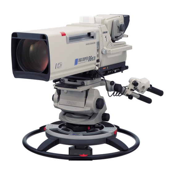
Functions for coloring the VF detail signal, flickering the The HDC1000R is a 2/3-type high-definition video camera VF detail signal by adding modulation, thickening the VF for studio and OB-van use for 2,200,000 pixels. It... -
Page 6: Basic System Configuration
The detail levels of three hues can be adjusted shown in the figures has been discontinued. independently at the same time. For advice on choosing devices, please contact your Sony dealer or a Sony sales representative. Detail boost-frequency control The boost frequency can be adjusted from 20 to 30 MHz. - Page 7 BKP-7911 Script Holder Zoom Lens CNU-700 (for studio use) HDVF-EL100 Camera Command HDVF-700A Network Unit Viewfinder Zoom Lens (for studio use) HDC1000R “Memory Stick” CAC-6 Return Video Selector V-wedge shoe (supplied with Intercom Headset RCP-700/900-series the tripod) MSU-900/950 Remote Control Panel...
-
Page 8: Precautions
Smear Precautions When an extremely bright object, such as a strong spotlight or flashlight, is being shot, vertical tails may be produced on the screen, or the image may be distorted. Note on laser beams Aliasing Laser beams may damage the CCDs. If you shoot a scene that includes a laser beam, be careful not to let a laser beam When fine patterns, stripes, or lines are shot, they may become directed into the lens of the camera. -
Page 9: Locations And Functions Of Parts
Locations and Functions of Parts Right Side and Left Side Right side a Up tally lamp b Safety lock c Camera number plate d Side panel lock screws e Lens lock and knob g Accessory bracket OUTPUT PROMPTER REMOTE CRANE TRACKER DC OUT CONTROL f Cable clamp... - Page 10 a Up tally lamp j TEST OUT (test signal output) connector (BNC Lights when the camera receives a red tally signal. type) When the CALL button on the MSU-900/950 Master To output the analog signal. Setup Unit or the RCP-700/900-series Remote Control This also supplies the VBS signal, an HD signal nearly Panel is pressed, the lamp lights if previously off or goes equal to the signal output from the VF connector, an HD-...
- Page 11 OFF: When the connected microphone requires no external power. +48 V: When the connected microphone requires an external power source. A power of +48 V is supplied to the microphone. (No function has been assigned to the uppwermost position. No power is supplied to the microphone.) Note To supply a power of +12 V, modification of the camera is required.
-
Page 12: Rear Panel
Rear Panel e; H-POSI control wlWIDTH control wkV-POSI control wj HEIGHT control z CURSOR ON button y CURSOR STORE button x RET 1 button a Video signal select buttons w RET 2 button b POWER indicator c ND filter selector RET 1 RET 2 POWER... - Page 13 h SCREEN SIZE MARKER switch Green: Power is being supplied to the camera. Red: Power is being supplied to the camera, but the CAM To control the display of the screen size marker as follows: PW button of the MSU-900/950 Master Setup Unit or ON ( ): Areas outside the specified ratio area will be RCP-700/900-series Remote Control Panel is set to...
- Page 14 p VF DETAIL (viewfinder detail) control v RET 1 knob Adjust the amount of detail of the picture on the viewfinder This knob selects from the four return signals from the screen when the VF DETAIL switch is set to ON. This has CCU.
- Page 15 Intercom Panel For JN3 (USA, Canada, and other countries) models ENG PROD ENG PROD PGM1 PGM2 PGM1 PGM2 INTERCOM INTERCOM INTERCOM 1 INTERCOM 2 g INTERCOM 2 connector a INTERCOM 1 connector b ENG/PROD switch f MIC switch c PGM1 control e PGM2 control d INTERCOM control d INTERCOM control...
- Page 16 For CED (Europe) model a INTERCOM 1 connector c MIC2 switch b MIC1 switch d INTERCOM 2 connector MIC1 TRACKER MIC2 PROD PROD PROD PGM1 PGM2 INTERCOM 1 INTERCOM 2 i PGM2 control h TRACKER control g PGM1 control f PROD control e ENG control a INTERCOM 1 connector (XLR 5-pin) h TRACKER control...
-
Page 17: Attaching Accessories
Firmly attach the V-wedge shoe to the camera, and mount the camera to the tripod as described below: the camera to the tripod securely. Otherwise the camera may fall down. HDC1000R Bottom of the video camera V-wedge shoe (supplied Tripod... -
Page 18: Attaching The Lens To The Camera
Attaching the Lens to the Camera Attach a hanger-mount-type lens recommended by Sony. Note For details on the lens, refer to the instruction manual Be sure to check the following two points before attaching furnished with the lens. the lens: •... -
Page 19: Attaching The 7- Or 9-Type Viewfinder
Attaching the 7- or 9-Type Viewfinder For details on attaching a viewfinder, refer to the Note instruction manual furnished with the viewfinder. Be sure that the VF connector on the viewfinder mount is positioned at a right angle to the control panel of the Proceed as follows: camera as shown below. -
Page 20: Setting The Focus Assist Function
Detaching the viewfinder Setting the Focus Assist Before detaching the viewfinder, check the following two points: Function • That the lift-release knob of the viewfinder is at its lowest position • That the locking lever is fixed Using the OPERATION menu, the assist functions for Proceed as follows: easier focusing on the viewfinder, can be activated. -
Page 21: Displaying The Focus Assist Indicators
The <VF DETAIL> page is displayed. Displaying the Focus Assist Indicators <VF DETAIL> 04 TOP VF DETAIL : CRISP The focus assist indicator function extracts the FREQUENCY: FAT MODE : irregularities of a subject and converts the integrated values FLICKER AREA to a level indicator, which shows the focus condition. -
Page 22: Setting The Camera Outputs
value. Use this setting when an optimum sensitivity value cannot be obtained, depending on the shooting environment. Setting the Camera 2) Normally, the optimum offset is automatically set in conjunction with the AREA MARKER SIZE and MASTER GAIN set values. Use this Outputs setting when the optimum offset cannot be obtained, depending on the shooting environment. - Page 23 To output as VBS Note Menu page Item Setting With the settings for outputting the same image as that on the viewfinder, the output will be obtained in 1080i, even <POWER SAVE> DOWN CONVERTER ACTIVE if the format setting is 720P. <DOWN CONVERTER>...
-
Page 24: Viewfinder Screen Status Display
Viewfinder Screen Status Display Besides the video image, the viewfinder can display text status, as well as items such as a center marker or safety and messages showing the camera settings and operation zone marker. When the DISPLAY switch is set to ON Items set to ON using the menu or related switches will be displayed on the upper and lower edges of the screen. -
Page 25: Menu Operations
When you set the MENU SELECT switch to Menu Operations CANCEL The status display is changed to show the following items: The menus displayed on the viewfinder enable various a Assignable switch indication settings of the camera. b Format indication The following parts are used to operate the menus. -
Page 26: Selecting Pages
Availabel menus Selecting Pages USER menu When selecting a page from a CONTENTS This menu can include menu pages selected from OPERATION, PAINT, MAINTENANCE, FILE, and page DIAGNOSIS menus for convenience. Changing, adding, and deleting pages can be perfomed with the USER Example: CONTENTS page of the OPERATION menu MENU CUSTOMIZE menu. -
Page 27: Setting The Menu Items
The “?” mark will change back to the arrow marker To change other setting items on the same menu page, ), and operations with the displayed page are repeat steps 1 through 4. enabled. To specify a character string To return to the TOP MENU screen When you press the MENU SELECT switch toward Align the arrow marker ( ) with “TOP”... - Page 28 CONTENTS Menu page title USER Source menu / page No. menu 01.EDIT PAGE 02.USER 1 EDIT 03.USER 2 EDIT 04.USER 3 EDIT <VF OUT> OPERATION 05.USER 4 EDIT 06.USER 5 EDIT <VF DETAIL> OPERATION 07.USER 6 EDIT 08.USER 7 EDIT 09.USER 8 EDIT <FOCUS ASSIST>...
- Page 29 The item selected in step 1 moves to the position that 1 Turn the MENU SELECT knob until the page that has the desired items appears, then press the you selected in step 3. MENU SELECT switch toward ENTER. In the above example, “ASSIGNABLE” is moved to Turn the MENU SELECT knob to move the arrow the top and the other items are moved down one line.
- Page 30 Turn the MENU SELECT knob to move the arrow ITEM DELETE marker ( ) to where you want to add the page, then DELETE OK? 01.<VF OUT> press the MENU SELECT switch toward ENTER. 02.<VF DETAIL> 03.<FOCUS ASSIST> 04.<VF DISPLAY> 05.<'!' IND>...
-
Page 31: Menu List
Menu List This section shows the menus to be displayed on the Notes viewfinder in tables. CCU: HDCU1000/1500 Camera Control Unit • For the pages that have been registered in the USER Execute by ENTER: Execute by pushing on the MENU menu at the factory, the USER menu page numbers are SELECT switch to ENTER. - Page 32 Page title Item Default Settings Remarks <'!' IND> [IND] ON ON, OFF [IND]: Set whether to be (U05) included in the status [NORMAL] 1 – – – – 1, 2, 3, 4, 5 (combination indications on the allowed) viewfinder (see page 25). [IND] ON ON, OFF [NORMAL]: Specify the...
- Page 33 Page title Item Default Settings Remarks <VF DETAIL> VF DETAIL ON, OFF (U02) 0 to 100% CRISP –99 to +99 FREQUENCY 9M, 14M, 18M FAT MODE ON, OFF FLICKER ON, OFF AREA 100% 100%, 70%, 60%, 50%, 40% ZOOM LINK 0%, 25%, 50%, 75%, 100% COLOR DETAIL ON, OFF...
- Page 34 Page title Item Default Settings Remarks <SWITCH ASSIGN1> ASSIGNABLE OFF, EXTENDER, 5600K, Note (U09) FAN MAX, D.EXTENDER When you turn D.EXTENDER ON or OFF, noise may be generated. This is not a malfunction. RE.ROTATION STD, RVS Specify operation mode of the MENU SELECT knob.
- Page 35 Page title Item Default Settings Remarks <RECEIVE SEL2> INTERCOM2 SEPARATE SEPARATE, MIX RECEIVE SELECT INTERCOM LEFT RIGHT, LEFT, BOTH, - - - JN3 model only LEFT RIGHT, LEFT, BOTH, - - - CED model only PROD LEFT RIGHT, LEFT, BOTH, - - - CED model only PGM1 RIGHT...
-
Page 36: Paint Menu
PAINT Menu Menu page Item⁄ Default Settings Remarks <SW STATUS> FLARE ON, OFF GAMMA ON, OFF BLK GAM ON, OFF KNEE ON, OFF WHT CLIP ON, OFF DETAIL ON, OFF LVL DEP ON, OFF SKIN DTL ON, OFF MATRIX ON, OFF <VIDEO LEVEL>... - Page 37 Menu page Item⁄ Default Settings Remarks <SATURATION> SATURATION –99 to +99 ON, OFF LOW KEY SAT –99 to +99 RANGE HIGH LOW, L.MID, H.MID, HIGH ON, OFF TEST OFF, SAW, 3STEP, 10STEP <KNEE> [R] [G] [B] [M] R, G, B, and M (master) values K POINT –99 to +99 can be independently set.
- Page 38 Menu page Item⁄ Default Settings Remarks <SKIN DETAIL> SKIN DTL ON, OFF SKIN GATE OFF, 1, 2, 3, (MAT) 1, 2, 3: Skin gate can be set to ON for the specified channel only (MAT): Displayed when GATE of <MULTI MATRIX> is ON. Highlighted: ABS (Absolute) mode Skin tone detail function can be (ON) OFF OFF...
- Page 39 Menu page Item⁄ Default Settings Remarks <SHUTTER> SHUTTER ON, OFF JN3 model: 59.94i: 1/100, 1/125, 1/250, Step shutter setting 1/100 (sec) 1/500, 1/1000, 1/2000 CED model: 50i: 1/60, 1/125, 1/250, 1/60 (sec) 1/500, 1/1000, 1/2000 29.97PsF: 1/40, 1/60, 1/120, 1/125, 1/250, 1/500, 1/1000, 1/2000 25PsF: 1/33, 1/50, 1/100, 1/125, 1/250, 1/500,...
-
Page 40: Maintenance Menu
MAINTENANCE Menu Menu page Item⁄ Default Settings Remarks <AUTO SETUP> AUTO BLACK Execute by ENTER. AUTO WHITE Execute by ENTER. AUTO LEVEL Execute by ENTER. AUTO WHITE SHADING Execute by ENTER. AUTO BLACK SHADING Execute by ENTER. TEST OFF, SAW, 3STEP, 10STEP <WHITE SHADING>... - Page 41 Menu page Item⁄ Default Settings Remarks <AUTO IRIS> AUTO IRIS ON, OFF WINDOW 1, 2, 3, 4, 5, 6 Select the auto iris windows: The shaded parts indicate the area where light detection occurs. OVERRIDE –99 to +99, - - To set the override to temporarily change the reference value for brightness...
- Page 42 Menu page Item⁄ Default Settings Remarks <TEST OUT> OUTPUT SD-SYNC, HD-SYNC, VF, (U16) (PWR SAVE) Displayed in POWER SAVE mode only VBS-OUT CHARACTER ON, OFF GAIN –127 to +127 CHROMA –127 to +127 SETUP ON, OFF JN3 model only (displayed when the format is NTSC) HD SYNC-OUT V-PHASE...
- Page 43 Menu page Item⁄ Default Settings Remarks <OTHERS 2> MENU RESUME OPE & USER OPE & USER, ALL, OFF DATE TYPE 5 M/D/Y 1 Y/Mn/D Y: Year 2 Mn/D Mn: Month (numeric) 3 D/M/Y M: Month (character string) 4 D/M D: Day 5 M/D/Y 6 M/D FILTER WHT MEM...
-
Page 44: File Menu
FILE Menu Five types of files can be used for easy adjustments of the For the specific items included in these files, refer to the camera; Operator, Reference, Scene, OHB, and Lens. Maintenance Manual. You can store the items set with the OPERATION menu and customized USER menu in the Operator file. - Page 45 Menu page Item⁄ Default Settings Remarks <REFERENCE> STORE FILE Execute by ENTER. To store the current settings of the reference file items in the reference file in internal memory. STANDARD Execute by ENTER. To read the standard values in the reference file in internal memory.
-
Page 46: Diagnosis Menu
DIAGNOSIS Menu This menu is only for viewing and no setting is made using this menu. Menu page Item Indication Remarks <OPTICAL LEVEL> CCU→CAM GREEN, YELLOW, RED, NG, NO With CCU connected only SIGNAL CAM→CCU GREEN, YELLOW, RED, NG, NO With CCU connected only SIGNAL <BOARD STATUS>... -
Page 47: Using A "Memory Stick
—Very humid or subject to corrosive substances Precautions • To prevent data loss, make backups of data frequently. In no event will Sony be liable for any loss of data. • Unauthorized recording may be contrary to the Label side provisions of copyright law. -
Page 48: Specifications
Sony Corporation. Power requirements • “Memory Stick PRO Duo and AC 240 V, 1.7 A (max.) are trademarks of Sony Corporation. DC 180 V, 0.9 A (max.) • “MagicGate” and are trademarks DC 12 V, 10 A (max.) of Sony Corporation. - Page 49 HDVF-700A (7-type, monochrome) Always verify that the unit is operating properly before HDVF-EL100 (11-type, color) use. SONY WILL NOT BE LIABLE FOR DAMAGES BKP-7911 Script Holder (with script light) OF ANY KIND INCLUDING, BUT NOT LIMITED CAC-6 Return Video Selector TO, COMPENSATION OR REIMBURSEMENT ON “Memory Stick”...
- Page 50 Dimensions Unit: mm (inches) 463 ( 18 368 ( 14 388 ( 15 392 ( 15 442 ( 17 80 ( 3 368 ( 14 260 ( 10 15 ( OPTICAL CENTER Specifications...
- Page 51 The material contained in this manual consists of information that is the property of Sony Corporation and is intended sole- ly for use by the purchasers of the equipment described in this manual. Sony Corporation expressly prohibits the duplication of any...
- Page 52 Sony Corporation Printed in Japan 2009.02 13 HDC1000R (JN3/CED) 4-140-774-01(2) © 2009...