Yamaha MCR-E810 Service Manual
Micro component system dvd player
Hide thumbs
Also See for MCR-E810:
- Owner's manual (277 pages) ,
- Service manual (58 pages) ,
- Specifications (2 pages)
Table of Contents
Advertisement
MICRO COMPONENT SYSTEM
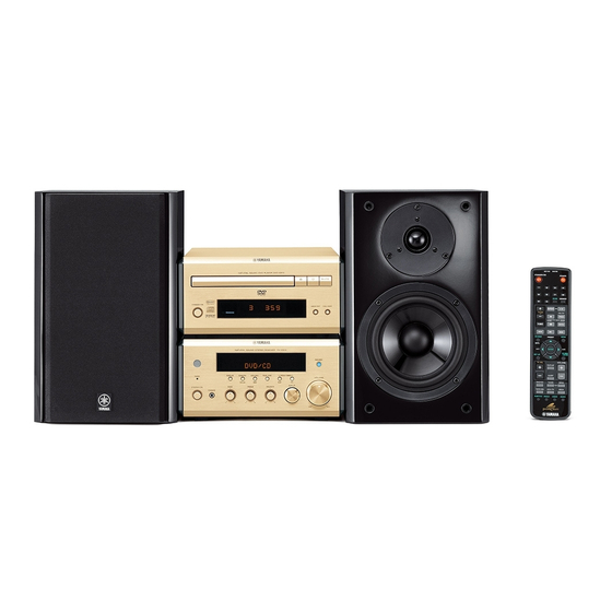
The MCR-E810 is composed of the DVD-E810, RX-E810 and NX-E800.
This service manual is for the DVD-E810.
For service manual of the RX-E810 and NX-E800, please refer to the following publication number:
This manual has been provided for the use of authorized YAMAHA Retailers and their service personnel.
It has been assumed that basic service procedures inherent to the industry, and more specifically YAMAHA Products, are already
known and understood by the users, and have therefore not been restated.
WARNING:
IMPORTANT:
The data provided is believed to be accurate and applicable to the unit(s) indicated on the cover. The research, engineering, and
service departments of YAMAHA are continually striving to improve YAMAHA products. Modifications are, therefore, inevitable
and specifications are subject to change without notice or obligation to retrofit. Should any discrepancy appear to exist, please
contact the distributor's Service Division.
WARNING:
IMPORTANT:
I CONTENTS
TO SERVICE PERSONNEL ...................................... 2-3
LOCALE MANAGEMENT INFORMATION ................... 4
FRONT PANEL .............................................................. 5
REAR PANELS .............................................................. 5
SPECIFICATIONS ...................................................... 6-7
INTERNAL VIEW ........................................................... 7
REPAIR NOTES ............................................................. 7
TRADE MODE ................................................................ 8
1 0 1 0 1 7
DVD-E810
SERVICE MANUAL
RX-E810/RX-E410/NX-E800
IMPORTANT NOTICE
Failure to follow appropriate service and safety procedures when servicing this product may result in personal
injury, destruction of expensive components, and failure of the product to perform as specified. For these reasons,
we advise all YAMAHA product owners that any service required should be performed by an authorized
YAMAHA Retailer or the appointed service representative.
The presentation or sale of this manual to any individual or firm does not constitute authorization, certification or
recognition of any applicable technical capabilities, or establish a principle-agent relationship of any form.
Static discharges can destroy expensive components. Discharge any static electricity your body may have
accumulated by grounding yourself to the ground buss in the unit (heavy gauge black wires connect to this buss).
Turn the unit OFF during disassembly and part replacement. Recheck all work before you apply power to the unit.
DISASSEMBLY PROCEDURES ................................... 9
TEST MODE ................................................................. 10
BLOCK DIAGRAM ....................................................... 11
WIRING DIAGRAM ...................................................... 12
PRINTED CIRCUIT BOARDS ................................ 13-16
SCHEMATIC DIAGRAMS ...................................... 17-22
REPLACEMENT PARTS LIST .............................. 24-25
SYSTEM CONTROL .............................................. 26-33
2006
All rights reserved.
This manual is copyrighted by YAMAHA and may not be copied or
redistributed either in print or electronically without permission.
MCR-E810
DVD PLAYER
101019
P.O.Box 1, Hamamatsu, Japan
'06.08
Advertisement
Table of Contents

Related Manuals for Yamaha MCR-E810


Summary of Contents for Yamaha MCR-E810
-
Page 1: Table Of Contents
This manual has been provided for the use of authorized YAMAHA Retailers and their service personnel. It has been assumed that basic service procedures inherent to the industry, and more specifically YAMAHA Products, are already known and understood by the users, and have therefore not been restated. -
Page 2: To Service Personnel
DVD-E810 I TO SERVICE PERSONNEL AC LEAKAGE TESTER OR WALL EQUIPMENT 1. Critical Components Information EQUIVALENT OUTLET UNDER TEST Components having special characteristics are marked Z and must be replaced with parts having specifications equal to those originally installed. 2. Leakage Current Measurement (For 120V Models Only) When service has been completed, it is imperative to verify INSULATING that all exposed conductive surfaces are properly insulated... - Page 3 DVD-E810 WARNING Warning for power supply The primary side of the power supply carries live mains voltage when the player is connected to the mains even when the player is switched off ! This primary area is not shielded so it is possible to touch copper tracks and/or components when servicing the player. Service personnel have to take precautions to prevent touching this area or components in this area.
-
Page 4: Prevention Of Electrostatic Discharge
DVD-E810 I PREVENTION OF ELECTROSTATIC DISCHARGE The laser diode in the DVD mechanism may be damaged due to static electricity from clothes or the human body. Use caution to prevent electrostatic damage when servicing or handling the DVD-mechanism. 1. Grounding for electrostatic damage prevention Some devices, such as the DVD player, use an optical pickup (laser diode) that will be damaged by static electricity in the working environment. -
Page 5: Front Panel
DVD-E810 I FRONT PANEL DVD-E810 (U, C, T, K, A, B, G, L, V models) I REAR PANELS DVD-E810 (U, C models) DVD-E810 (A model) DVD-E810 (T model) DVD-E810 (B, G models) DVD-E810 (K, L, V models) -
Page 6: Specifications
DVD-E810 I SPECIFICATIONS PLAYBACK SYSTEM GENERAL DVD Video, VR (Video Recording) format (DVD-RW) Dimensions (W x H x D) 215 x 108 x 330 mm Video CD & SVCD (8-7/16" x 4-1/4" x 13") Weight 2.3 Kg (5 lbs. 1 oz) Picture CD Finish Gold color (T, A models) -
Page 7: Internal View
DVD-E810 I INTERNAL VIEW • DIMENSIONS MONO P.C.B. SCART P.C.B. (B, G models) AV P.C.B. Power Supply Unit DVD Mechanism FRONT P.C.B. 215 (8-7/16") Unit: mm (inch) I REPAIR NOTES None of the components of the following unit can be supplied separately. Each unit must be replaced as a whole in case of a failure. -
Page 8: Trade Mode
DVD-E810 I TRADE MODE This unit provides TRADE mode which prevents the tray from opening even when the “OPEN/CLOSE” key is pressed. • Activating TRADE mode The power to the main unit should be turned on before activating the TRADE mode. 1. -
Page 9: Disassembly Procedures
DVD-E810 I DISASSEMBLY PROCEDURES See REPLACEMENT PARTS LIST for item numbers. When disassembling, use the special screw driver with tip shape in figure. Mounting Top Cabinet [240] 2.7 mm Remove 4 screws. [250] (4 on side) Remove 4 screws. [251] (4 on rear side) Lift top cabinet from rear side to remove. -
Page 10: Test Mode
DVD-E810 I TEST MODE • Starting Test Mode a. Connect the power cable to the AC outlet. b. Press the “STANDBY/ON” key while simultaneously pressing “NEXT/F.FWD” and “STOP” keys of the main unit. At this time, keep pressing “NEXT/F.FWD” and “STOP” keys for 8 seconds or longer. c. -
Page 11: Block Diagram
DVD-E810 I BLOCK DIAGRAM • See page 22 → SCART MONO SCHEMATIC DIAGRAM COAXIAL B, G models • See page 19, 20 → • See page 17, 18 → 7111 SCHEMATIC DIAGRAM Dual SCHEMATIC DIAGRAM DIGITAL OUT Video B,G,R CVBS NJM2267M (SCART) OPTICAL... -
Page 12: Wiring Diagram
DVD-E810 I WIRING DIAGRAM AV (SCART) 15FE-BT-VK-N SYS_CTRL ANALOG L/R OPT. SPDIF COAX SPDIF YUV/CVBS 1300 1809 1801 1802 1803 1804 1805 1806 SCART P.C.B. 30FE-BT-VK-N 30FE-BT-VK-N 1807 1201 1003 MCLK MCLK P8_CTR BCLK BCLK P8_CTR P16_CTR DAC_STB DAC_STB P16_CTR LRCLK LRCLK CVBS... -
Page 13: Printed Circuit Boards
DVD-E810 The first digit of a component indicates the component type. 1xxx : Connector 3xxx : Resistor 5xxx : Coil 7xxx : IC, Transistor, FET I PRINTED CIRCUIT BOARDS 2xxx : Capacitor 4xxx : SMD jumper 6xxx : Diode 9xxx : Wire jumper FOR INFORMATION ONLY (NO SERVICE PARTS WILL BE AVAILABLE) MONO P.C.B. - Page 14 DVD-E810 The first digit of a component indicates the component type. 1xxx : Connector 3xxx : Resistor 5xxx : Coil 7xxx : IC, Transistor, FET 2xxx : Capacitor 4xxx : SMD jumper 6xxx : Diode 9xxx : Wire jumper AV P.C.B. Top View AV P.C.B.
- Page 15 DVD-E810 The first digit of a component indicates the component type. 1xxx : Connector 3xxx : Resistor 5xxx : Coil 7xxx : IC, Transistor, FET 2xxx : Capacitor 4xxx : SMD jumper 6xxx : Diode 9xxx : Wire jumper FRONT P.C.B. Top View PROGRESSIVE STANDBY/ON AV P.C.B.
- Page 16 DVD-E810 The first digit of a component indicates the component type. 1xxx : Connector 3xxx : Resistor 5xxx : Coil 7xxx : IC, Transistor, FET 2xxx : Capacitor 4xxx : SMD jumper 6xxx : Diode 9xxx : Wire jumper SCART P.C.B. Top View (B, G models) AV P.C.B.
-
Page 17: Schematic Diagrams
DVD-E810 The first digit of a component indicates the component type. 1xxx : Connector 3xxx : Resistor 5xxx : Coil 7xxx : IC, Transistor, FET I SCHEMATIC DIAGRAMS 2xxx : Capacitor 4xxx : SMD jumper 6xxx : Diode 9xxx : Wire jumper FOR INFORMATION ONLY (NO SERVICE PARTS WILL BE AVAILABLE) MONO 1/2 1101 D1... - Page 18 DVD-E810 The first digit of a component indicates the component type. 1xxx : Connector 3xxx : Resistor 5xxx : Coil 7xxx : IC, Transistor, FET 2xxx : Capacitor 4xxx : SMD jumper 6xxx : Diode 9xxx : Wire jumper MONO 2/2 1201 D5 4210 G5 1206 A8...
- Page 19 DVD-E810 The first digit of a component indicates the component type. 1xxx : Connector 3xxx : Resistor 5xxx : Coil 7xxx : IC, Transistor, FET 2xxx : Capacitor 4xxx : SMD jumper 6xxx : Diode 9xxx : Wire jumper AV 1/2 1800 F9 1813 F10 2105 B2...
- Page 20 DVD-E810 The first digit of a component indicates the component type. 1xxx : Connector 3xxx : Resistor 5xxx : Coil 7xxx : IC, Transistor, FET 2xxx : Capacitor 4xxx : SMD jumper 6xxx : Diode 9xxx : Wire jumper AV 2/2 1802 B9 3261 E5 1803 D9...
- Page 21 DVD-E810 The first digit of a component indicates the component type. 1xxx : Connector 3xxx : Resistor 5xxx : Coil 7xxx : IC, Transistor, FET 2xxx : Capacitor 4xxx : SMD jumper 6xxx : Diode 9xxx : Wire jumper FRONT 1100 C1 1103 E1 1104 F1...
- Page 22 DVD-E810 The first digit of a component indicates the component type. 1xxx : Connector 3xxx : Resistor 5xxx : Coil 7xxx : IC, Transistor, FET 2xxx : Capacitor 4xxx : SMD jumper 6xxx : Diode 9xxx : Wire jumper SCART (B, G models) 1300-1 A4 1300-2 A4 1302 D2...
- Page 23 DVD-E810 MEMO MEMO MEMO MEMO...
-
Page 24: Replacement Parts List
DVD-E810 I REPLACEMENT PARTS LIST B, G models 8100 1004 Bracket B 8106 1003 Bracket A 8107 1005 1002 1001 346 (K, L, V models) 347 (K, L, V models) 1006... - Page 25 DVD-E810 WARNING G Components having special characteristics are marked s and must be replaced with parts having specifications equal to those originally installed. ✻ New Parts...
-
Page 26: System Control
DVD-E810 I SYSTEM CONTROL 1. External Bus 1.1. Physical format of external bus It is composed of 2 bus lines. MCR-E810 RX command line RX unit DVD unit (RX-E810) (DVD-E810) State info. line 1.2. Format of RX command RX command is the request of RX to DVD unit. - Page 27 DVD-E810 Example: Process Eject Initialize Power on Loading Stop Seek Play Pause Play Skip Play Search Play H x 2/3 H x 1/3 Reset start "STANDBY/ON" "EJECT" Load "PLAY" "PAUSE" "PLAY" "SKIP" "SEARCH" "PLAY" Process Play Stop Seek Play Eject Loading Stop Seek Play...
- Page 28 DVD-E810 2. Command and Operation Key Code The system command and the system remote control code described as follows are transmitted through RX command bus. 2.1 RX request command Name Code Function POWER_ON 7C-F6 Power on request POWER_OFF 7C-F7 Standby request PLAY 7C-82 Playback request...
- Page 29 DVD-E810 3. Command Communication for System Function 3.1 Power on (1) Power on by RX “STANDBY/ON” key operation RX turns on the power by RX’s “STANDBY/ON” key and at the same time DVD also turns on the power if DVD state is power on at the last RX’s power on.
- Page 30 DVD-E810 DVD unit can turn on the power by also other key, “PLAY” or “OPEN/CLOSE (EJECT)”. In this case, it carries out a peculiar function to the key after processing power on. However, only the power on processing is done by “PLAY” key without media. When the system is in power on state and DVD unit is in standby state, only DVD unit is changed into power on state by this operation.
- Page 31 DVD-E810 3.3 Standby (power off) (1) System standby The power supply through AC outlet of RX is shut down in system standby (power off). The microcomputer of the unit connected with AC outlet of RX cannot work after system power off. When there is processing that should be finished before the system power off, the system is turned power off after such processing completion.
- Page 32 DVD-E810 (3) Auto standby (power off) When 30 minutes pass with the following conditions consisted, the system turns off the power (standby) automatically. a. The unit connected with an external bus is in the standby state. b. RX input function is DVD. c.
- Page 33 DVD-E810 3.4 Display control (1) Display dimmer function This is the function to change the brightness of DVD’s display by operating RX. RX unit DVD unit Display dimmer on operation DIMMER_ON command Display dimmer on Display dimmer on Display dimmer off operation DIMMER_OFF command Display dimmer off Display dimmer off...
- Page 34 DVD-E810...