
Related Manuals for Husqvarna BZ 27


Summary of Contents for Husqvarna BZ 27
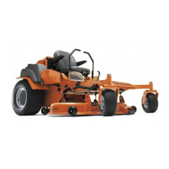
- Page 1 Operator´s manual BZ 27 BZ 34 Please read these instructions carefully and make sure English you understand them before using the machine.
-
Page 3: Table Of Contents
Contents Contents...1 Introduction ...3 Congratulations...3 General ...3 Driving and Transport on Public Roads ...3 Towing ...3 Operating ...3 Good Service ...4 Manufacturing Number ...4 Symbols and Decals ...5 Safety Instructions...7 General Use...7 Personal Safety Equipment ...9 Driving on Slopes...10 Children...11 Maintenance ...12 Transport...15 Customer responsibilities...16... - Page 4 WARNING! Failure to follow cautious operating practices can result in serious injury to the operator or other persons. The owner must understand these instructions, and must allow only trained persons who understand these instructions to operate the mower. Each person operating the mower must be of sound mind and body and must not be under the influence of any mind altering substance.
-
Page 5: Introduction
Introduction Congratulations Thank you for purchasing a Husqvarna ride-on mower. This machine is built for the greatest efficiency and rapid mowing primarily of large areas. Controls in one place and a hydrostatic transmission regulated by steering controls also contribute to the machine’s performance. -
Page 6: Good Service
Good Service Husqvarna’s products are sold all over the world and only in specialized retail stores with complete service. This ensures that you as a customer receive only the best support and service. Before the product is delivered, the machine has, for example, been inspected and adjusted by your retailer, see the certificate in the Service Journal in this operator’s manual. -
Page 7: Symbols And Decals
SYMBOLS AND DECALS Symbols and Decals These symbols are found on the machine and in the operator’s manual. Study them carefully so that you know what they mean. WARNING! Xxxxxxx xxxx xxxxxxxx xxx x Xxxxx xxxxxx xx. xx xxxxxxxx xxxxx xxx xx. Used in this publication to notify the reader of a risk of personal injury or death , particularly if the reader should neglect to follow instructions given in the manual. - Page 8 SYMBOLS AND DECALS Read Shut off engine Operator´s and remove key Manual. before performing any maintenance or repair work. Whole body Severing of exposure to fingers and thrown toes. objects. English- Keep a safe Use on distance from slopes no the machine.
-
Page 9: Safety Instructions
SAFETY INSTRUCTIONS Safety Instructions These instructions are for your safety. Read them carefully. WARNING! This symbol means that important safety instructions need to be emphasized. It concerns your safety. IMPORTANT: THIS CUTTING MACHINE IS CAPABLE OF AMPUTATING HANDS AND FEET AND THROWING OBJECTS. - Page 10 SAFETY INSTRUCTIONS • Disengage blades when not mowing. Shut off engine, wait for all parts to come to a complete stop, and remove ignition key before cleaning the machine, removing the grass catcher, or unclogging the discharge guard. • Operate machine only in daylight or good artificial light.
-
Page 11: Personal Safety Equipment
SAFETY INSTRUCTIONS • All drivers should seek and obtain professional and practical instruction. Such instructions should emphasize: the need for care and concentration when working with ride-on machine; control of a ride-on machine sliding on a slope will not be regained by the aplication of the brake. -
Page 12: Driving On Slopes
SAFETY INSTRUCTIONS Slope Operation Slopes are a major factor related to loss of control and tip-over accidents, which can result in severe injury or death. Operation on all slopes requires extra caution. If you cannot back up the slope or if you feel uneasy on it, do not mow it. -
Page 13: Children
SAFETY INSTRUCTIONS Children Tragic accidents can occur if the operator is not alert to the presence of children. Children are often attracted to the machine and the mowing activity. Never assume that children will remain where you last saw them. •... -
Page 14: Maintenance
SAFETY INSTRUCTIONS Maintenance WARNING! The engine must not be started when the driver’s floor plate or any protective plate for the mower deck’s drive belt is removed. Safe Handling of Gasoline To avoid personal injury or property damage, use extreme care in handling gasoline. Gasoline is extremely flammable and the vapors are explosive. - Page 15 SAFETY INSTRUCTIONS • Check the fuel level before each use and leave space for the fuel to expand, because the heat from the engine and the sun may otherwise cause the fuel to expand and overflow. General Maintenance • Never operate machine in a closed area. •...
- Page 16 SAFETY INSTRUCTIONS • Acid in the eyes can cause blindness, contact a doctor immediately. • Be careful when servicing the battery. Explosive gases form in the battery. Never perform maintenance on the battery when smoking or near open flames or sparks. The battery can explode and cause serious injury/damage.
-
Page 17: Transport
SAFETY INSTRUCTIONS • Stop and inspect the equipment if you run over or into anything. If necessary, make repairs before starting. • Never make adjustments with the engine running. • The machine is tested and approved only with the equipment originally provided or recommended by the manufacturer. -
Page 18: Customer Responsibilities
(if any). If a spark arrester is used, it should be maintained in effective working order by the operator. A spark arrester for the muffler is available through your authorized Husqvarna dealer. English-... -
Page 19: Controls
Controls This operator’s manual describes the Husqvarna Zero Turn Rider. The mower is fitted with a liquid cooled, 3 cylinder Daihatsu diesel engine (27 HP) or Daihatsu Turbo diesel engine (34 HP) Transmission from the engine is made via two belt-driven hydrostat transaxles, which in turn drive a hydraulic motor for each drive wheel. -
Page 20: Gauges
Gauges Water temperature gauge- indicates coolant temperature and warns of overheat situation. Ammeter - indicates amount of electrical flow at the battery. Under normal operating conditions the needle will be slightly on the plus (+) side of the gauge, showing that current is being supplied to the battery. -
Page 21: Engaging The Mower Deck
CONTROLS Engaging the Mower Deck In order to engage the mower deck, pull the knob out; the mower deck is disengaged when the knob is depressed. Deck should be engaged at mid throttle and disengaged at idle speed to prolong clutch life. -
Page 22: Motion Control Levers
Motion Control Levers The machine’s speed and direction are continuously variable using the two motion control levers. The motion control levers can be moved forward or backward from a neutral position. Furthermore, there is a neutral position, which is locked if the motion control levers are moved outward into the neutral slots. -
Page 23: Hydraulic Lift Switch
CONTROLS If the steering controls are in uneven positions when standing still, they can be adjusted using the adjustment screws, not the link system, for the controls BAM-7 Adjusting screws Hydraulic Lift Switch Used to raise and lower the mower deck hydraulically. -
Page 24: Refueling
Refueling The machine has two fuel tanks, one on each side just behind the seat. The tanks hold 11.4 gallons, 5.7 gallons each. The engine is run on clean, fresh, diesel fuel with a minumum of 40 cetane. WARNING! Diesel fuel is highly flammable. -
Page 25: Hydraulic Lift For Mower Deck
Manual Lifting Lever with Foot Assist for the Mower Deck The lifting lever is used to place the mower deck in the transport position or one of the 17 different cutting height positions. The cutting height is set by placing a pin in the hole for the desired cutting height and the pin is then locked on the inside (hidden in the illustration) with the supplied cotter pin. -
Page 26: Relays
Relays The relays and glow plug timer are located in a holder to the right side of the seat. Tracking The tracking knob is located in front of the left control lever. Rotating this knob allows fine tuning adjustments so that the machine tracks straight with the drive levers in the full forward position. -
Page 27: Operation
Operation Read "Safety Instructions" section and following pages, if you are unfamiliar with the machine. Training Zero turn mowers are far more manueverable than typical riding mowers due to their unique steering capabilities. We recommend that this section be reviewed in its entirety prior to attempting to move the mower under its own power. -
Page 28: Before Starting
Before Starting • Read the sections Safety Instructions and Controls before starting the machine. • Perform the daily maintenance before starting (see Maintenance Schedule in the Maintenance section). • Check that there is sufficient fuel in the fuel tanks. • Adjust the seat to the desired position. - Page 29 Disengage the mower blades by depressing the blade switch. Move the steering controls outward to the locked (outer) neutral position. Move the throttle to the middle position. OPERATION 1. Deck lift switch 2. Mower deck knob Steering controls in the outward, locked neutral position Set the throttle BAM-2...
- Page 30 Open the fuel valve for the selected fuel tank. Press in and turn the ignition key to the start position. IMPORTANT INFORMATION Wait till the glow plug light goes out or damage could result to the engine When the engine starts, immediately release the ignition key back to the run position.
-
Page 31: To Start An Engine With A Weak Battery
10. Set the desired engine speed with the throttle. Allow the engine to run at a moderate speed, ”half throttle”, for 3-5 minutes before loading it too heavily. USE FULL THROTTLE WHEN MOWING. WARNING! Engine exhaust and certain vehicle components contain or emit chemicals considered to cause cancer, birth defects, or other reproductive system... -
Page 32: Running
To attach jumper cables • Connect each end of the RED cable to the POSITIVE (+) terminal on each battery, taking care not to short against chassis. • Connect one end of the BLACK cable to the NEGATIVE (-) terminal of the fully charged battery. - Page 33 On power units push the hydraulic lift switch froward to lower the deck to the selected pin position. WARNING! Make sure that no one is near the machine when engaging the blade switch. Engage the mower deck by pulling out the blade switch.
-
Page 34: Operating On Hills
Operating on hills Read the Safety Instructions "Driving on Slopes" in the "Safety Instructions" section WARNING! Do not drive up or down hills with slopes greater than 10 degrees. And do not drive across any slopes. • The slowest speed possible should be used before starting up or down hills. -
Page 35: Mowing Tips
Mowing Tips • Observe and flag rocks and other fixed objects to avoid collisions. • Begin with a high cutting height and reduce it until the desired mowing result is attained. The average lawn should be cut to 2 1/2" (64 mm) during the cool season and over 3"... -
Page 36: Stopping The Engine
Stopping the Engine Allow the engine to idle a minute in order to attain normal operating temperature before stopping it, if it has been worked hard. Avoid idling the engine for longer periods, as there is a risk of the spark plugs fouling. Disengage the mower deck by depressing the blade switch. -
Page 37: Moving By Hand
Moving by Hand In order for the machine to be moved with the engine turned off, the vent screws on both hydraulic pumps must be opened 1/4-1/2 turn. WARNING! No adjustments or maintenance to be carried out unless: - the engine stopped, - the ignition key has been removed, - the parking brake is on. -
Page 38: Maintenance
Maintenance Maintenance Schedule The following is a list of maintenance procedures that must be performed on the machine. For those points not described in this manual, visit an authorized service workshop. An annual service carried out by an authorized service workshop is recommended to maintain your machine in the best possible condition and to ensure safe operation. - Page 39 Maintenance Check/adjust throttle Check the condition of belts, belt pulleys, etc. Change the engine oil Replace the engine oil filter (every 200 hours) Clean/replace the spark plugs Replace the fuel filter Replace the air filter (main cartridge) (every 200 hours) Check the caster wheels (every 200 hours) Clean the cooling fins Clean fins of oil cooler (Kohler)
-
Page 40: Battery
Battery Your mower is equipped with a maintenance free battery and does not need servicing. However, periodic charging of the battery with an automotive type battery charger will extend its life. • Keep battery and terminals clean. • Keep battery bolts tight. •... -
Page 41: Checking The Safety System
Connect BLACK grounding cable to negative (-) battery terminal with remaining hex bolt and hex nut. 10. Fit the terminal guard. 11. Lower seat. Checking the Safety System The machine is equipped with a safety system that prevents starting or driving under the following conditions. -
Page 42: Checking The Engine's Cooling Air Intake
Checking the Engine's Cooling Air Intake Check that the engine’s cooling air intake is free from leaves, grass, and dirt. If the cooling air intake is clogged, engine cooling deteriorates, which can lead to engine damage. Checking and Adjusting the Throttle Cable Check that the engine responds to throttle increases and that a good engine speed is... -
Page 43: Air Filter Maintenance
Replacing the Air Filter If the engine seems weak or runs unevenly and the dust load indicator has turned red the air filter may be clogged. If run with a clogged air filter, disruption of operation can occur. For this reason, it is important to replace the air filter regularly (see the heading Maintenance Schedule for the proper service interval). - Page 44 Filter replacement Unfasten the two plastic clamps on the sides of the air filter cover. Remove the air filter cover. Remove the main filter (outer filter) by pulling it out by hand. Lightly brush or use mild air pressure to clean. Only remove and replace safety element after the paper filter has been replaced 3 or 4 times.
-
Page 45: Replacing The Fuel Filter
Replacing the Fuel Filter The fuel filter is located with the priming pump. Replace the fuel filter every 800 hours (once per season) or more regularly if it becomes clogged. Replace the filter as follow: Unscrew fuel filter from pump and replace. Every 50 hours check for water in the fuel filter. - Page 46 It is extremely important that when antifreeze is used, that it be mixed with water in a separate container before adding. NEVER add straight antifreeze to the radiator. Recommended mix is 50/50 lowtox (propylene glycol) phosphate-free antifreeze with tap water. DO NOT mix in ethylene glycol.
-
Page 47: Checking The Parking Brake
Checking the Parking Brake Visually check that no damage is found on the lever, links, or switch belonging to the parking brake. Perform a test drive and check that there is sufficent braking action. To adjust the parking brake: Set brake lever (D) fully forward against stop. -
Page 48: Checking The V-Belts
Checking the V-belts Deck belt Check every 100 hours of operation. Check for severe cracking and large nicks. NOTE: The belt will show some small cracks in normal operation. To replace belt lower the deck to its lowest position. Remove the foot plate and belt shields. -
Page 49: Checking The Blades
To reinstall belt: Swing pump idler pulley toward engine to route belt around it. Then route belt around the pulley for left pump first. Reinstall idler spring and use the ratchet to rotate idler so the belt may be installed all the way around the last pulley. - Page 50 Blade replacement: WARNING! Blades are sharp. Protect your hands with gloves and/or wrap blades with a heavy cloth when handling. • Remove blade bolt by turning counterclockwise. • Tunnel deck blades are sharpened on both sides and can be installed either way.
-
Page 51: Adjusting The Mower Deck
Adjusting the Mower Deck WARNING! Before performing any service or adjustment checklist: 1. Engage the parking brake. 2. Place the blade-switch in the disengaged position. 3. Turn ignition switch to “OFF” position and remove the key. 4. Make sure the blades and all moving parts have completely stopped. 5. - Page 52 To adjust anti-scalp rollers Anti-scalp rollers are properly adjusted when they are just slightly off of the ground when the deck is at the desired cutting height in the operating position. Anti-scalp rollers then keep the deck in the proper position to help prevent scalping in most terrain conditions.
-
Page 53: Checking Hydraulic System
Checking the Hydraulic System Total System Capacity...1.125 gal. To check the hydraulic fluid level, locate the hydraulic reservoir under the seat. Remove cap and check level. Fill to 1/4" from top of tank WARNING! If a leak is suspected, use a piece of cardboard or wood, NOT your hands. -
Page 54: Motion Control Linkage Adjustment
Motion Control Linkage Adjustment This adjustment must be made with the rear wheels rotating. Raise the rear of the machine and block it up so the wheels are free to rotate WARNING! Keep hands, feet and clothing away from rotating tires. Place a 2 x 4 board between the foot plate and the center of the seat to engage the seat safety switch. -
Page 55: Deck Lift Power Unit
Deck Lift Power Unit The system is pre-filled and factory sealed. In the event it becomes necessary to replace oil in the reservoir, the cylinder or cylinders must be in the retracted position. Carefully remove all dirt and debris from around the fill plug and remove the plug. -
Page 56: Cleaning And Washing
Cleaning and Washing Regular cleaning and washing, especially under the mower deck, will increase the machine’s lifespan. Make it a habit to clean the machine directly after use (after it is cooled), before the dirt sticks. Do not spray water on the top of the mower deck. -
Page 57: Lubrication
Lubrication Lubrication Schedule Lubrication schedule 12/12 Every year Lubricate with grease gun 1/52 Every week 1/365 Every day General Remove the ignition key to prevent unintentional movements during lubrication. When lubricating with an oil can, it must be filled with engine oil. When lubricating with grease, unless otherwise stated, use a high grade molybdenum disulfide grease. -
Page 58: Lubricating The Cables
Lubricating the Cables If possible, grease both ends of the cables and move the controls to end stop positions when lubricating. Refit the rubber covers on the cables after lubrication. Cables with sheaths will bind if they are not lubricated regularly. If a cable binds, it can disrupt operation. If a cable binds, remove the cable and hang it vertically. - Page 59 3. Engine Oil Changing the Engine Oil The engine oil shall be changed for the first time after 50 hours of operation. Thereafter, it should be changed every 150 hours. WARNING! The engine and the exhaust system, become very hot during operation.
- Page 60 LUBRICATION The oil level shall lie between the markings on the dipstick. If the level is approaching the ”ADD” mark, top up the oil to the ”FULL” mark on the dipstick. Never fill above the ”FULL” mark. The oil is filled through the hole for the dipstick.
- Page 61 6. Front Wheel Bearings Lubricate with a grease gun, one zerk for each set of wheel bearings, until the grease is forced out. Use only good quality molybdenum disulphide grease. Grease from well-known brand names (petrochemical companies, etc.) usually maintains a good quality. 7.
- Page 62 9. Steering Control Shafts Tip the driver’s seat. Lubricate with a grease gun, one zerk for each steering control shaft, until the grease is forced out. Use only good quality molybdenum disulphide grease. Grease from well-known brand names (petrochemical companies, etc.) usually maintains a good quality.
- Page 63 12. Belt Adjuster, Hydraulic Pumps Lubricate using a grease gun, one zerk, until the grease squeezes out. Use only good quality molybdenum disulphide grease. Grease from well-known brand names (petrochemical companies, etc.) usually maintains a good quality. IMPORTANT INFORMATION Use minimal lubrication and remove excess lubricant so that is does not come into contact with belts or belt pulley drive surfaces.
-
Page 64: Trouble Shooting Guide
TROUBLE SHOOTING GUIDE Trouble Shooting Guide Problem The engine will not start. The starter does not turn the engine over. The engine runs rough. The engine seems weak. English- Cause • The blade switch is engaged. • The steering controls are not locked in the neutral position. - Page 65 TROUBLE SHOOTING GUIDE The engine overheats. Battery not charging. The machine moves slowly, unevenly, or not at all. Mower deck not engaging. • Clogged air intake or cooling fins. • Engine overloaded. • Poor ventilation around engine. • Defective engine speed regulator. •...
- Page 66 TROUBLE SHOOTING GUIDE Uneven mowing results. The machine vibrates. English- • Different air pressure in the tires on the left and right sides. • Bent blades. • The chains for suspending the mower deck are uneven. • The chain fixture has come loose. •...
-
Page 67: Storage
Service When ordering spare parts, please specify the purchase year, model, type, and serial number. Always use genuine Husqvarna spare parts. An annual check-up at an authorized service workshop is a good way to ensure that your machine performs its best the following season. -
Page 68: Wiring Diagram
WIRING DIAGRAMS Wiring diagram 6. Seat unoccupied 8. Blade switch in OFF position 11. Brake switch OFF pos. 14-15. Motion control levers OUT 1. Battery 2. Accessory outlet 3. Key switch 4. To engine pigtail 5. Hour meter 6. Seat switch 7. -
Page 69: Technical Data
Technical Data Engine Manufacturer Type Power Lubrication Oil capacity excl filter Oil capacity incl filter Engine oil (See viscocity digram) Fuel Fuel tank capacity Cooling Air filter Alternator Starter Transmission Transmission Speed and direction controls Speed forward Speed reverse Brakes Front caster tires, Smooth tread Rear tires, Turf pneumatic Tire pressure, front and rear... - Page 70 Equipment Cutting width Cutting height (Tunnel Ram Deck) Cutting height (Combi Deck) Uncut circle Number of blades Blade length (Tunnel Ram Deck) Blade length (Combi Deck) Blade tip speed Anti-scalp rollers-Tunnel Ram Deck Anti-scalp rollers-Combi Deck Frame construction Ball beared wheels Sprung standard seat Hinged armrests Hour meter...
-
Page 71: Accessories
Accessories Front baffle kit Mulch kits ROPS Roll Over Protection System Torque Specifications ·Engine crankshaft bolt ·Deck pulley bolts-Tunnel Ram Deck ·Deck pulley bolts-Combi Deck ·Hydraulic tube nuts ·Wheel motor hub nut ·Lug nuts ·Blade bolt -Tunnel Ram Deck ·Blade bolt -Combi Deck ·Standard 1/4”... -
Page 72: Conformity Certificates
Only applicable to European versions Husqvarna AB, Beatrice NE USA declares under sole responsibility that the machine types stated on page 1 of this manual, from 2005's serial numbers and onwards (the year is clearly stated in plain text on the... -
Page 73: Service Journal
Service Journal Action Delivery Service 1. Charge the battery. 2. Mount the rear wheels. 3. Adjust the tire pressure of all wheels to 15 PSI (1 bar). 4. Mount the steering controls in the normal position. 5. Connect the seat fold-up stop. 6. - Page 74 Action 20. Inform the customer about: The need and advantages of following the service schedule. The need and advantages of leaving the machine for service every 300 hours. The effects of service and maintaining a service journal on the machine’s resale value. Application areas for BioClip.
-
Page 75: 25-Hour Service
SERVICE JOURNAL Action 25-Hour Service Check the hydraulic system’s oil level. Check the tire pressures. Lubricate the belt adjuster, mower deck. Lubricate the belt adjuster, hydraulic pumps. Check/clean the engine’s cooling air intake. Clean cyclon air filter dust cap. Lubricate the belt adjuster, mule drive - 72” only. Date, mtr reading, stamp, sign English-... -
Page 76: 50-Hour Service
Action 50-Hour Service Perform the 25-hour service. Lubricate the front wheel bearings. Lubricate the steering control shafts. Lubricate the mower deck struts. Lubricate the cutting height adjuster. Change oil and oil filter for the first time. See engine manual. 7. Check dust load indicator on air filter. Change filter only if indicator is red. -
Page 77: 100-Hour Service
SERVICE JOURNAL Action 100-Hour Service Perform the 25-hour service. Perform the 50-hour service. Change engine oil at 150 hours. See engine manual. Check fuel pump filter. See engine manual. Check fam belt clearance. See engine manual. Clean the cooling fins on the engine and transmission. Date, mtr reading, stamp, sign English-... -
Page 78: 300-Hour Service
Action 300-Hour Service Inspect the machine. Come to agreement with the customer as to which additional work is to be carried out. Perform the 25-hour service. Perform the 50-hour service. Perform the 100-hour service. Change the oil and filter in the hydraulic system. Clean the combustion chamber and grind the valve seats. -
Page 79: At Least Once Each Year
SERVICE JOURNAL Action At Least Once Each Year Clean the engine’s cooling air intake (25 hours). Replace the air cleaner’s paper cartridge. Replace the air filter’s main cartridge (200 hours). Change the engine oil (150 hours). Replace the engine oil filter (300 hours). Change the oil and filter in the hydraulic system (300 hours). - Page 80 SERVICE JOURNAL Action Date, mtr reading, stamp, sign English-...
- Page 81 SERVICE JOURNAL Action Date, mtr reading, stamp, sign English-...
- Page 82 SERVICE JOURNAL Action Date, mtr reading, stamp, sign English- ´®z+R8@¶6Y¨ ´®z+R8@¶6Y¨...
- Page 83 SERVICE JOURNAL Action Date, mtr reading, stamp, sign English-...
- Page 84 115 02 43-26 ´®z+R8@¶6Y¨ 2006W18 ´®z+R8@¶6Y¨...