Table of Contents
Advertisement
Quick Links
Download this manual
See also:
Quick Manual
Advertisement
Table of Contents

Related Manuals for Samsung SRM-872


Summary of Contents for Samsung SRM-872
- Page 1 NETWORK VIDEO RECORDER User Manual SRM-872...
- Page 2 Samsung Techwin. Disclaimer Samsung Techwin makes the best to verify the integrity and correctness of the contents in this document, but no formal guarantee shall be provided. Use of this document and the subsequent results shall be entirely on the user’s own responsibility.
-
Page 3: Important Safety Instructions
Overview IMPORTANT SAFETY INSTRUCTIONS Read these operating instructions carefully before using the unit. Follow all the safety instructions listed below. Keep these operating instructions handy for future reference. 1) Read these instructions. 2) Keep these instructions. 3) Heed all warnings. 4) Follow all instructions. - Page 4 • SAMSUNG retains the copyright on this manual. • This manual cannot be copied without SAMSUNG's prior written approval. • We are not liable for any or all losses to the product incurred by your use of non-standard product or violation of instructions mentioned in this manual.
- Page 5 Operating Temperature The guaranteed operating temperature range of this product is -25°C ~ 50°C (-13°F ~ 122°F). This product may not work properly if you run right after a long period of storage at a temperature below the guaranteed one. Prior to using a device that has been stored for a long period in low temperatures, allow the product to stand at room temperature for a period.
-
Page 6: Table Of Contents
Contents Overview Product Features Package Contents Front & rear view and details IO Box Control Box Installation Disassemble Brackets Mount product Install IO & Control box Vehicle installation Surveillance Start / END system Log in Shutdown system Live monitoring screen OSD icons Contextual Menu on Live Live screen division... - Page 7 Playback(Search) Backup Web Client Access Smartviewer Auto v1.0 Smartviewer AUTO v1.0 Setup Callback Mobile viewer iPolisAuto Appendix System Specification Default Configurations IO BOX Installation Connector Pin Map...
-
Page 8: Product Features
Product Features • Provide Ultimate reliability with embedded linux System • Dedicated Database structure for more stability. • CMS(Central Monitoring System) support • Use same UI on NVR, CMS and web viewer. • Web monitoring, Searching and setup available. • Built in Media Player for backup playback •... -
Page 9: Package Contents
Package Contents The following components are included in product box NVR Main unit IO BOX Control Box Power cable(1ea) RS232 connect cable(2ea) RJ45 UTP cable (2ea) GPS Antenna Remote Control & Battery CD (User manual) Quick Guide HDD fi x screw and Key Rear cover ... -
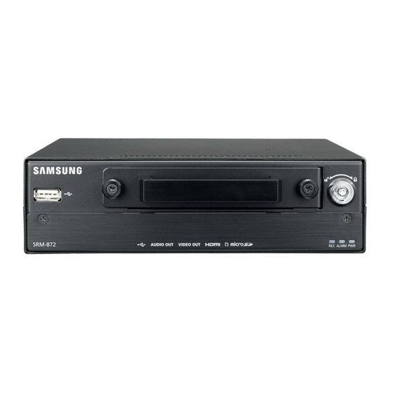
Page 10: Front & Rear View And Details
Front & rear view and details Front ⑩ ① ⑤ ⑥ ⑦ ⑧ ⑨ ② ③ ④ Name Description Connect USB module when use WiFi or 3G WiFi / 3G USB communication(optional) USB port Use for mouse connection or external storage. Audio output Sound output as line output Video output... - Page 11 Rear ③ ④ ⑥ ⑤ ② ① Name Description Connect IP cameras. System supports power over Ethernet when Poe Camera use PoE IP camera NETWORK Connect network cable for CMS and Web view CONTROL BOX Connect to control box IO BOX 1 Connect to IO box Connect power supply from vehicle Connect GPS Antenna (SMA type)
-
Page 12: Io Box
IO Box Front ② ① name Description Display following status. LED Display -Link : Shows connection status of IO BOX Dip Switch Set moving direction of vehicle. *For more details, see page 62 ‘IO BOX Installation’. Rear ② ① ④ ③... -
Page 13: Control Box
CONTROL BOX Front ① ③ ② name Description Emergency Start Emergency Recording with this button. POWER Display power on status of control box Light on when storage(HDD, SD) storage is available Light on when storage (HDD, SD) is not available. LED lights Light on GPS position fixed after receiving data Light on when ‘Shutdown delay’... -
Page 14: Installation
Installation Disassemble Brackets 1. Open box and take out product. Then separate bottom bracket with screw(1) in picture. 2. Place ‘bottom bracket’ on even place and assemble main unit and bracket with screw(2) in picture. 3. Assemble rear cover and main unit with screw(3) in picture. -
Page 15: Install Io & Control Box
Install IO & Control box * Connect IO box and Control box with provided cable as above picture. ST = screw tightening power Tighten screw with recommended torque... -
Page 16: Vehicle Installation
Vehicle Installations When install on the bottom, fix the brackets on main unit to the bracket which installed on bottom with 6 screws. Caution: When installed on bottom, it may cause HDD shock issues. For the torque of screws, see the pictures on previous page. -
Page 17: Surveillance
Surveillance Start/End system Before install on vehicle, user should set system first. Connect VGA or HDMI monitor If monitor doesn’t display because of resolution, press and hold ‘zoom’ key on remote controller for 5seconds. It adjust system resolution automatically. Log in 1. -
Page 18: Live Monitoring Screen
Live Monitoring screen Monitoring system with VGA or HDMI output on control box after installation on Vehicle. ① ② ③ ④ ⑤ Name Description Menu Open NVR menu. HDD status Display HDD used status with percentage. Turn on when archiving data Turn on when sequencing mode works Turned on when HDD is set as overwrite mode Turned on system receiving GPS data... -
Page 19: Osd Icons
OSD Icons Following status icons displayed on each channels. name Description name Description No Recording(greed) Pre Event Rec.(blue) Recording (Red) Motion Detection Emergency Recording Sensor Detection Event Recording (red) IP Camera event High Resolution Detection Playback* Displays when it’s over than following recorded size and it shows 1fps speed. (4 division 1280x720 60fps, 9 division : 1280x720 30fps) Contextual Menu on Live Press right mouse button to see Contextual menu. -
Page 20: Live Screen Division
Audio Select audio channel Backup Playback recorded data Playback Move to search playback mode. Emergency Rec. Start emergency recording. Display current system log Setup Open setup menu * The Audio sound output in live mode is based on the channel configuration in ‘Menu-Audio’. It has not same as current selected channel. -
Page 21: Live Monitoring
Live Monitoring Select ‘Live Monitoring’ on live view. It displays Live status of connected camera and transmitting status. Recording status Select ‘Record Monitoring’ on live view. It displays recording status of connected camera and transmitting status. Emergency Recording Record immediately on live mode 1. -
Page 22: System Setup
SYSTEM SETUP System information General information setup 1. Press menu and move to SYSTEM->Information. 2. Enter NVR name. (Easy to recognize in multiple device access) 3. Set ID on ‘Remote Controller’. User can control multi NVRs with single remote controller with changing IDs. -
Page 23: System Upgrade
System Upgrade Upgrade system firmware with new version. 1. Press Menu and move to ‘SYSTEM->Information’ system page. 2. Insert USB memory which contains update file. 3. Press ‘Update’ button and select file. 4. Start upgrade with selected file. 5. System restarts automatically when update completed. -
Page 24: Holiday Setup
Holiday setup Set specific day or days as holiday and apply different recording schedule. 1. Move to Holiday tab menu on Date & time setup. 2. Press button and set date. 3. Press ‘OK’ to apply setup. Note: Holiday may not same date every year. User may have to update every year. -
Page 25: User Setup
User setup User can define new user and group permissions. Add new User 1. Press menu and move to ‘SYSTEM-User’. 2. Press button and add new user. 3. Enter user name with virtual keyboard and select user group. 4. Set password for new user. *Auto Login: Log in automatically with selected user. -
Page 26: System Log
System Log All system log can be searched in this page. 1. Press Menu and move to SYSTEM->SYSTEM Log. 2. To view latest log, press ‘Reload’ button and update logs. Use button to move next pages. To Export Log file 1. -
Page 27: Device
DEVICE In this menu, Set configuration of camera, audio, alarm. Change Camera Title 1. Press Menu and move to ‘DEVICE->Camera’ page. 2. Select camera and press to change title. 3. Use virtual key and set new camera name. IP camera setup Enter IP camera information and authorize it to check its working status. - Page 28 Live Profile 1. Move to ‘Device->Camera->Live profile’ page. 2. It shows profiles of connected camera. User can select profiles on each cameras and adjust codec & resolutions only available camera. Profile: Shows available profile on connected cameras. Codec: type of Image compressing algorithm. ...
-
Page 29: Profile Setup
PROFILE SETUP Network camera generally provides single or multiple profiles and user can select details such as live, recording and network transmit profiles. System shares added profiles. Once you edit profile on live, record or Network, it updates other profiles. ... -
Page 30: Audio
Audio Audio Connect NVR records sounds on each channels. 1. Press Menu and move to ‘DEVICE->Audio’ page. 2. Select audio channel and change title as desired name. 3. Press ‘OK’ to save changes Note: Audio input is only available with camera. -
Page 31: Alarm
Alarm Set alarm type and schedule. Set Alarm type and duration 1. Press Menu and move to ‘Device-Alarm’ page. 2. Set duration of alarm activation.(5sec to 10min) 3. Select alarm channel and change title as desired name. 4. Choose type of alarm -NO: Normal Open. -
Page 32: Display
Display Set monitor display and display language 1. Press Menu and move to Display page. 2. Set your language and other display options. 3. To change display resolution, select ‘Resolution’ menu and select desired one. 4. Press ‘OK’ to save changes Channel popup by Event Display (popup) event triggered channel for a configured time. - Page 33 PIP (Picture In Picture) Setup Press Menu and move to ‘Display-PIP’ page. Set ‘Size’ and ‘Position’. Press ‘OK’ to save changes. Note: PIP is only available on single live display. Resolution setup 1. Press Menu and move to ‘Display-resolution’ page. 2.
-
Page 34: Record Setup
Record Setup Set storage and recording options. Set Storage 1. Press Menu and move to ‘Record->Storage’. 2. System displays installed HDD(s) on list. 3. To use HDD as storage, select one of HDD and press ‘Format’ button below. 4. Press ‘close’ once format process is end. Note: ‘Record’... - Page 35 Event recording setup 1. Move to Event page 2. Set ‘Pre-Event’ Duration ‘On’ and set time. System will record previous data from event triggered. 3. Set time for Emergency Record. ‘No Limit’ setup record until off Emergency Rec. 4. Event record duration is for general event recording duration.
-
Page 36: Network
Network Set IP address 1. Press Menu and move to ‘Network->Address- >WAN’ page. 2. Set one of IP address type. *No IP address setup required in ‘DHCP’ option. 3. In 'Static IP’ option, you need to enter ‘IP address, Subnet mask and Gateway’. 4. -
Page 37: Set Port
Set Port Press Menu and move to ‘Network->Address- >Port’ page. 2. Set port for ‘Remote monitoring, Playback and setup. Default is ‘10101’. * Set Live port and other port sets automatically. 3. Set port for Web viewer. Default is ‘80’. 4. -
Page 38: Email Setup
Notify event through network Use provided feature and send message to specified IP and E-mail. Callback Setup 1. Press Menu and move to ‘Network->Notification -> Callback’ page. 2. Set callback interval. * The triggered event between intervals would not be delivered. It only delivers new event as callback message after interval. - Page 39 Network Transmission Adjust network data streaming option and optimize it. 1. Press Menu and move to ‘Network- >Transmission->Transmission page. 2. Set network bandwidth according to you network speed. 3. Press ‘Ok’ to save changes. Network profile Select profile for live monitoring. See details for profile section before Audio.
-
Page 40: Event
EVENT Set event related options such as Sensor, Motion, Video Loss, System, G-sensor and IP camera. About Event activation and activate Recording, Alarm and Notification Each triggered event can be activated following actions. 1. Record: start recording on selected multiple channels. 2. - Page 41 System Notification Notify system status through alarm and Callback. 1. Set level of Storage full. System start notification when storage reaches this level. 2. Set temperature level you desired to get notification on S.M.A.R.T. Threshold. 3. Set alarm and Notification.(see examples above) G-Sensor Notification Detect movements such as sudden acceleration, stop and suspected as accident.
-
Page 42: Calendar Search
Playback (Search) Time search (Go to Time) 1. Click right mouse button on live mode and select ‘Playback’ 2. Select storage that has recorded data. 3. System enters ‘Playback(Search)’ mode 4. Click right mouse button again and select ‘Go to’. 5. -
Page 43: Event Search
Event Search Provides easy search by recorded event list 1~3. Same as ‘Time Search’. 4. Click right mouse button again and select ‘Event Search’ 5. Select the date and type of event to find specific data. * Events are searched by 1,000ea and press >> button to see next 1,000 events. - Page 44 BACKUP Backup Recorded Data 1. Click right mouse button on live mode 2. Select Backup and choose type.(backup or AVI maker) 3. Insert USB memory on system USB slot. 4. Select Device for backup data(generally USB memory is used) 5. Set backup data period and camera. 6.
-
Page 45: Web Client Access
Web client access Access System with using web browser. 1. Run web browser and enter IP address of NVR or DDNS address. 2. Enter ID and Password in log in page. 3. Press buttons (Live, playback) and move to new windows. 4. - Page 46 5. Detail usage is same as remote client software. See ‘Smart viewer’ part on next page. If no ‘Active X’ installed, run explorer with ‘Run as Administrator’ option. To upload file on IE(internet Explorer), set options on ‘Tools->Internet option->Security- >Customer level’.
-
Page 47: Smartviewer Auto V
Smartviewer AUTO v1.0 Monitoring live view, search and other features on remote place through network. Start Remote software(S.W should be installed on your PC) 1. Double click remote s.w and run it. 2. It displays main screen. Minimum resolution: 1024x620. Recommended resolution: 1280x1024 3. - Page 48 Favorite setup Manage multiple site. Up to 64 different cameras and sites can be monitored. 1. Start Remote software 2. Press button and select ‘Favorite’ tab. 3. Press ‘Add’ button. 4. Enter group name and description. 5. Select ‘Layout’ and choose layout. 6.
- Page 49 Displays NVR tracking under playback mode. GPS data is recorded with images using built in GPS on Mobile NVR. This data will be displayed on Google Map under playback mode. You can check latitude, longitude, speed, direction angle etc. Remote Playback (Search) 1.
- Page 50 Go to Time 1. Click icon and enter time. 2. Click icon to refresh and update calendar information. 3. Playback image with control buttons. Event Search 1. Press event search icon in playback mode. 2. Select the date, event type and camera. 3.
- Page 51 Playback backup data 1. Run remote software. 2. Press ‘connect’ button. 3. Click ‘Backup’ tab and select backup file. 4. Click ‘Connect’ button to playback. Playback HDD data on PC 1. Connect HDD with USB cables. 2. Remote s.w should be installed on PC. 3.
-
Page 52: Smartviewer Auto V1.0 Setup
Smartviewer AUTO v1.0 Setup Remote Software setup Click and ‘Setup’ to enter Remote software setup menu. System Product: Displays general information of the S/W Software Version: Displays current S/W version Secondary Monitor: Select the secondary monitor when using multi monitors on PC ... - Page 53 Sequence Set sequence mode and sites from registered sites 1. Move to ‘Sequence’ tab on Setup. 2. Select the site on the list left side. 3. Click > button and add to sequence list. 4. To move all sites, click >> button.
-
Page 54: Remote Upgrade
REMOTE setup connected Devices 1. Connect NVR first. connect * if not connected, press button and connect device first. 2. Click button on top of right and select ‘Remote Setup’. 3. Display connected device’s setup screen as same as local device. *Setup menu and usage is same as local device. - Page 55 Call Back ‘Callback’ installed together with remote software. Callback receives event list from NVRs through network. 1. Go to ‘Start->Program->Nemon2’ and run ‘Nemon Callback2’. 2. Callback Icon displayed on windows task bar. 3. Click Callback icon to display Callback window. 4.
-
Page 56: How To Use
MobileViewer iPolisAuto User can do live view, Search playback and setup configuration on mobile device. (Android / iOS) How to use 1. Search with the key word ‘iPolisAuto’ in ‘App Store’ or ‘Play Store’. Android Description iPhone Press android’s menu button In iOS, use buttons to see the detail menu. - Page 57 3. Search Android Description iPhone In Search mode, there are Event, Time information displays. Click date and it displays event lists on selected date. To do time search, press and hold time line for 3 seconds, it displays time on selected position. Adjust desired event or time to load recorded data and you can control playback with control buttons.
-
Page 58: System Specification
Appendix System Specification Video SRM-872 N/W Camera Inputs Up to 8CH Resolution CIF, VGA, 4CIF, 1.3M, 2M, 3M Protocols ONVIF Installation Camera Setup Resolution, Frame rate, bit rate setup. Viewer Built-in Webviewer Multi Screen 1/4/9 Monitor display Performance Embedded Linux... - Page 59 Power Shutdown Delay 1 Min. ~ 30 Min. (User selectable) Management General Electrical Input Voltage 12V ~ 24V DC Power Max. 30 W consumption Camera Power Max. 8 W per channel, Total 64W(PoE, IEEE 802.3af ) Output Operating Environmental -25°C to +50°C (-13°F to +122°F) / 20% to 85% RH Temp./Humidity ㆍ...
-
Page 60: Default Configurations
Default Configurations Classification Details Value NVR Name None System Remote controller ID Company None Manufacture None Model None Information Registration No. None Vehicle License No. None Driver None System shut down Delay Time zone System Daylight saving Date & Time Date YY-MM-DD Time... - Page 61 Pre event duration Emergency Record Event No Limite Duration Post Event Duration 1 min. From ~ to 00:00~24:00 Schedule mode Time & event Camera Setting Full frame Type Static IP IP Address 192.168.1.200 Subnet mask 255.255.255.0 Gateway 192.168.1.1 DDNS server address automatically DNS server 8.8.8.8...
-
Page 62: Io Box Installation
IO BOX Installation 1. Cautions on Installation Inside IO Box G-Sensor included. Mind following installation guide when install. No matter where you install, maintain level with your vehicle. Install parallelize with vehicle moving direction and X, Y, Z axis on product case. Check moving direction and axis and set DIP switch on front properly. -
Page 63: Connector Pin Map
Connector Pin Map 1. Power connector VCC/ACC input range is 12Vdc ~ 24Vdc. VCC power pin should be connected to battery on vehicle and connect ACC power pin to accessory power on vehicle. ACC. Power means the power on when turn key at ‘ACC’ mode.. 2. - Page 64 3. UTP Cable Pin Map (IO Box 1/2, Ctrl Box) RJ-45 Connector Pin map IO Box1 IO Box2 Ctrl Box Not use Not use Not use Not use Not use IO Box TXD Not use Analog Audio VCC 12V Not use VCC 12V VCC 12V Not use...
- Page 65 5. IO Box D-SUB15 Pin Map Alarm / Sensor Alarm/Sensor Signal 1 Signal 5 Signal 2 Signal 6 Signal 3 Signal 7 Signal 4 Signal 8 Sensor input connection Connect one of sensor signal line to ‘Signal’ port and the other to ‘GND port. ...
- Page 66 Problem Action The system does not turn on Check if the power supply system is properly connected. and the LED indicator on the Check the system for the input voltage from the power source. front panel does not work at all. ...
-
Page 67: Open Source License Report On The Product
OPEN SOURCE LICENSE REPORT ON THE PRODUCT GPL Software : linux kernel, u-boot, busybox, parted, ntfs-3g LGPL Software : glibc, ffmpeg OpenSSL License : OpenSSL Apache License : mDNSResponder /------------------------------------------------------------------------/ GNU GENERAL PUBLIC LICENSE Version 2, June 1991 Copyright (C) 1989, 1991 Free Software Foundation, Inc. - Page 68 These requirements apply to the modified work as a whole. If identifiable sections of that work are not derived from the Program, and can be reasonably considered independent and separate works in themselves, then this License, and its terms, do not apply to those sections when you distribute them as separate works. But when you distribute the same sections as part of a whole which is a work based on the Program, the distribution of the whole must be on the terms of this License, whose permissions for other licensees extend to the entire whole, and thus to each and every part regardless of who wrote it.
- Page 69 10. If you wish to incorporate parts of the Program into other free programs whose distribution conditions are different, write to the author to ask for permission. For software which is copyrighted by the Free Software Foundation, write to the Free Software Foundation;...
- Page 70 subroutine library, you may consider it more useful to permit linking proprietary applications with the library. If this is what you want to do, use the GNU Library General Public License instead of this License. /------------------------------------------------------------------------/ GNU LESSER GENERAL PUBLIC LICENSE Version 3, 29 June 2007 Copyright (C) 2007 Free Software Foundation, Inc.
- Page 71 are covered by this License. b) Accompany the Combined Work with a copy of the GNU GPL and this license document. c) For a Combined Work that displays copyright notices during execution, include the copyright notice for the Library among these notices, as well as a reference directing the user to the copies of the GNU GPL and this license document. d) Do one of the following: 0) Convey the Minimal Corresponding Source under the terms of this License, and the Corresponding Application Code in a form suitable for, and under terms that permit, the user to recombine or relink the Application with a modified version...
- Page 72 4. The names "OpenSSL Toolkit" and "OpenSSL Project" must not be used to endorse or promote products derived from this software without prior written permission. For written permission, please contact openssl-core@openssl.org. 5. Products derived from this software may not be called "OpenSSL" nor may "OpenSSL" appear in their names without prior written permission of the OpenSSL Project.
- Page 73 Apache License Version 2.0, January 2004 http://www.apache.org/licenses/ TERMS AND CONDITIONS FOR USE, REPRODUCTION, AND DISTRIBUTION 1. Definitions. "License" shall mean the terms and conditions for use, reproduction, and distribution as defined by Sections 1 through 9 of this document. "Licensor" shall mean the copyright owner or entity authorized by the copyright owner that is granting the License. "Legal Entity"...
- Page 74 (d) If the Work includes a "NOTICE" text file as part of its distribution, then any Derivative Works that You distribute must include a readable copy of the attribution notices contained within such NOTICE file, excluding those notices that do not pertain to any part of the Derivative Works, in at least one of the following places: within a NOTICE text file distributed as part of the Derivative Works;...
- Page 75 Samsung Techwin cares for the environment at all product manufacturing stages, and is taking measures to provide customers with more environmentally friendly products. The Eco mark represents Samsung Techwin’s devotion to creating environmentally friendly products, and indicates that the product satisfies the EU RoHS Directive.
- Page 76 SALES NETWORK SAMSUNG TECHWIN CO., LTD. Samsung techwin R&D Center, 701,Sampyeong-dong, Bundang-gu,Seongnam-si,Gyeonggi-do, Korea, 463-400 TEL : +82-70-7147-8740~60 FAX : +82-31-8018-3745 SAMSUNG TECHWIN AMERICA Inc . SAMSUNG TECHWIN EUROPE LTD. 100 Challenger Rd. Suite 700 Ridgefield Park, NJ 07660 Samsung House, 1000 Hillswood Drive, Hillswood Business Park...