Table of Contents
Advertisement
READ THIS MANUAL CAREFULLY!
It contains important safety information.
LIRE ATTENTIVEMENT CE MANUEL!
Il comprend d'importantes informations de sécurité.
¡LEA ESTE MANUAL ATENTAMENTE!
Contiene indicaciones importantes acerca de la seguridad.
MANUEL DU PROPRIÉTAIRE
MANUAL DEL PROPIETARIO
YFM45FGD/YFM45FGPD
YFM45FGPAD/YFM45FGPHD
YFM450FAD/YFM450FAPD
OWNER'S MANUAL
1CT-F8199-62
Advertisement
Table of Contents
Troubleshooting

Related Manuals for Yamaha Grizzly 450 YFM45FGPD


Summary of Contents for Yamaha Grizzly 450 YFM45FGPD
- Page 1 READ THIS MANUAL CAREFULLY! It contains important safety information. LIRE ATTENTIVEMENT CE MANUEL! Il comprend d’importantes informations de sécurité. ¡LEA ESTE MANUAL ATENTAMENTE! Contiene indicaciones importantes acerca de la seguridad. OWNER’S MANUAL MANUEL DU PROPRIÉTAIRE MANUAL DEL PROPIETARIO YFM45FGD/YFM45FGPD YFM45FGPAD/YFM45FGPHD YFM450FAD/YFM450FAPD 1CT-F8199-62...
- Page 2 PRINTED IN USA 2012.05-0.3×1 CR (E,F,S)
- Page 3 READ THIS MANUAL CAREFULLY! It contains important safety information. OWNER’S MANUAL YFM45FGD/YFM45FGPD YFM45FGPAD/YFM45FGPHD YFM450FAD/YFM450FAPD WARNING This ATV should not be ridden by anyone under 16 years of age. 1CT-F8199-62-E0...
- Page 4 Read this manual carefully before operating this vehicle. This manual should stay with this ve- hicle if it is sold. EC Declaration of Conformity conforming to Directive 2006/42/EC We, YAMAHA MOTOR CO., LTD. 2500 Shingai, Iwata, Japan, declare in sole responsibility, that the product YFM450FWA (YFM45FG) (5Y4AJ14W0C0520167–) (Make, model)
-
Page 5: Ec Declaration Of Conformity
EC Declaration of Conformity conforming to Directive 2006/42/EC We, YAMAHA MOTOR CO., LTD. 2500 Shingai, Iwata, Japan, declare in sole responsibility, that the product YFM450FWAD (YFM45FGP) (5Y4AJ47W0C0501901–) (YFM45FGPA) (5Y4AJ50W0C0500501–) (YFM45FGPH) (5Y4AJ48W0C0500401–) (Make, model) to which this declaration applies, conforms to the essential health... - Page 6 YFM45FGPHD/YFM450FAD/YFM450FAPD. This ATV represents the result of many years of Yamaha ex- perience in the production of fine sporting, touring, and pacesetting racing machines. With the purchase of this Yamaha, you can now appreciate the high degree of craftsmanship and reliability that have made Yamaha a leader in these fields.
- Page 7 EBU17330 IMPORTANT MANUAL INFORMATION EBU17342 FAILURE TO FOLLOW THE WARNINGS CONTAINED IN THIS MANUAL CAN RESULT IN SERIOUS IN- JURY OR DEATH. Particularly important information is distinguished in this manual by the following notations: This is the safety alert symbol. It is used to alert you to potential per- sonal injury hazards.
- Page 8 Please check your local riding laws and regulations before operating this ATV. EBU17410 YFM45FGD/YFM45FGPD/YFM45FGPAD YFM45FGPHD/YFM450FAD/YFM450FAPD OWNER’S MANUAL ©2012 by Yamaha Motor Co., Ltd. 1st edition, April 2012 All rights reserved. Any reprinting or unauthorized use without the written permission of Yamaha Motor Co., Ltd.
-
Page 9: Table Of Contents
EBU17420 TABLE OF CONTENTS LOCATION OF THE WARNING AND Fuel cock ..........4-16 SPECIFICATION LABELS ......1-1 Starter (choke) ..........4-18 Seat ............4-18 SAFETY INFORMATION ......2-1 Storage compartments ......4-19 Front carrier ..........4-22 DESCRIPTION ..........3-1 Rear carrier ..........4-22 Left view ............3-1 Adjusting the front and rear shock Right view............ - Page 10 Starting a warm engine ......6-3 Periodic maintenance chart Operating the drive select lever and for the emission control system ....8-3 driving in reverse ........6-3 General maintenance and lubrication Engine break-in .......... 6-5 chart ............8-5 Parking ............6-5 Removing and installing panels ....8-10 Parking on a slope ........
- Page 11 Adjusting the rear brake lever and CLEANING AND STORAGE ......9-1 brake pedal free play, and the brake Cleaning ............9-1 pedal height ..........8-41 Storage ............9-2 Axle boots ..........8-47 Brake light switches ......... 8-48 SPECIFICATIONS ........10-1 Checking and lubricating the cables ..8-48 Checking and lubricating the front and CONSUMER INFORMATION.......11-1 rear brake levers ........
-
Page 12: Location Of The Warning And Specification Labels
Read and understand all of the labels on your ATV. These labels contain important information for safe and proper operation. Never remove any labels from your ATV. If a label becomes difficult to read or comes off, request a replace- ment label from your Yamaha dealer. For Europe 9 10... - Page 13 < 40 kg ( 88 lbs) 37S-F817R-00 1P0-F816P-20 < 80 kg ( 176 lbs) 37S-F817R-10 25.0 kPa 25.0 kPa 0.25 kgf/cm² 0.25 kgf/cm² < 5880 N 3.6 psi 3.6 psi < 600 kgf < 1322 lbf 5FU-F816M-M0 < 147 N <...
- Page 14 YAMAHA 1HP-F811R-00 1P0-F816R-00...
- Page 15 11 YFM45FGD YFM450FWA 2012 19.4 kW YAMAHA MOTOR CO., LTD. 275 kg < 0.5 kg 2500 SHINGAI, IWATA, JAPAN 1CU-F155A-30 ( 1 lb ) 37S-F816N-00 11 YFM45FGPD YFM45FGPHD YFM450FWAD 2012 19.4 kW YAMAHA MOTOR CO., LTD. 281 kg 2500 SHINGAI, IWATA, JAPAN...
- Page 16 Familiarize yourself with the following pictograms and read the explanatory text, then make sure to check the pictograms that apply to your model. Read the Owner’s manual. NEVER use on paved roads. ALWAYS use an approved helmet and NEVER carry passengers. protective gear.
- Page 17 This unit contains high-pressure nitrogen Turning 4WD-LOCK gas. (“DIFF.LOCK”) takes more effort. Mishandling can cause an explosion. Do not Operate at a slow speed and allow extra incinerate, puncture or open. time and distance for maneuvers to avoid loss of control. This pictogram shows the loading limits and/or maximum load capacity for this ATV.
- Page 18 Year of construction Model Name **** ****** *** kW YAMAHA MOTOR CO., LTD. Max. Power *** kg 2500 SHINGAI, IWATA, JAPAN Mass In Running Order...
- Page 19 For Oceania...
- Page 20 25 kPa, (3.6 psi) 25 kPa, (3.6 psi) 22 kPa, (3.2 psi) 22 kPa, (3.2 psi) ( 6 0 0 k g f ) 5880 N 1322 5FU-F816M-20 ( 1 5 k g f ) 37S-F151K-00...
- Page 21 UNDER 1P0-F816L-00 1-10...
- Page 22 WARNING Fuel vapors can be a fire or explosion hazard. To avoid injury or death, never store fuel or flammable liquids in this storage compartment. Storage should not exceed 0.5 kg (1 lb) 37S-F151F-00 1-11...
-
Page 23: Safety Information
EBU17431 SAFETY INFORMATION ● EBU17505 Never allow a child under age 16 to operate an ATV without adult supervision, and never allow AN ATV IS NOT A TOY AND CAN BE HAZARD- continued use of an ATV by a child if he or she OUS TO OPERATE. - Page 24 ● Never operate at speeds too fast for your skills ● Never operate the ATV on hills too steep for the or the riding conditions. Always go at a speed ATV or for your abilities. Practice on smaller hills that is proper for the terrain, visibility, operating before attempting larger hills.
- Page 25 ● Always use proper procedures if you stall or roll reduced stopping ability. Test your brakes after backwards when climbing a hill. To avoid stall- leaving water. If necessary, apply them several ing, use the proper gear range and maintain a times to let friction dry out the linings.
- Page 26 In the event of an accident tion. If necessary, contact your riding party or 1. If serious injuries are incurred, you may be local authorities to let them know where you safer staying next to your vehicle; it may are and what has happened. shield you from oncoming riders.
- Page 27 This im- While you may find aftermarket products similar in proper position limits the freedom of movement design and quality to genuine Yamaha accesso- of the operator and may limit control ability, ries, recognize that some aftermarket accessories...
- Page 28 ● Do not run engine outdoors where engine EWB00072 WARNING exhaust can be drawn into a building through openings such as windows and Avoid Carbon Monoxide Poisoning All engine exhaust contains carbon monoxide, doors. a deadly gas. Breathing carbon monoxide can EWB02591 cause headaches, dizziness, drowsiness, nau- WARNING...
-
Page 29: Description
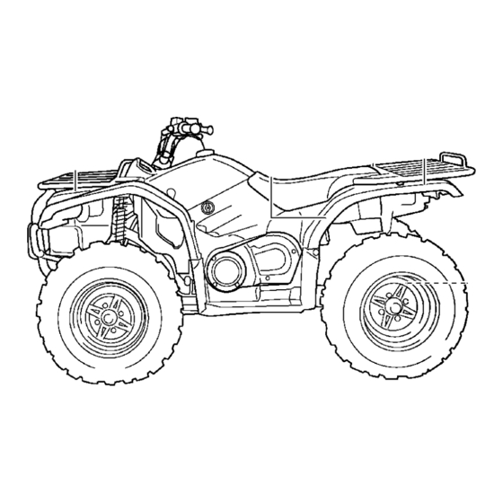
EBU17680 DESCRIPTION EBU17690 EBU17700 Left view Right view 1. Radiator cap 1. Rear shock absorber assembly spring preload adjusting ring 2. Fuel cock 2. Spark arrester 3. Throttle stop screw 3. Rear storage compartment and tool kit 4. Air filter case 4. -
Page 30: Controls And Instruments
EBU17712 Controls and instruments The ATV you have purchased may differ slightly 6 7 8 from the figures shown in this manual. 1. Rear brake lever 2. Handlebar switches 3. Starter (choke) 4. Horn switch 5. Drive select lever 6. Multi-function display 7. -
Page 31: Instrument And Control Functions
EBU17734 INSTRUMENT AND CONTROL FUNCTIONS EBU17760 Main switch The positions of the main switch are as follows: All electrical systems are supplied with power. The headlights and taillight come on when the light switch is on, and the engine can be started. The key cannot be removed. -
Page 32: Indicator Lights And Warning Lights
EBU26695 Indicator lights and warning lights 1. Electric Power Steering warning light “EPS” (for EPS model) 1. On-Command differential gear lock indicator light “DIFF. LOCK” EBU17990 Low-range indicator light “ ” 2. Low-range indicator light “L” This indicator light comes on when the transmis- 3. - Page 33 “ON”. If the warning engine as soon as it is safe to do so and allow it to light does not come on, have a Yamaha dealer cool down for about 10 minutes. check the electrical circuit.
- Page 34 ● ● If the engine is stopped using the engine stop Due to the synchronizing mechanism in the dif- switch and the key is in the “ON” position, the ferential gear case, the four-wheel-drive indica- EPS warning light comes on to indicate that the tor may not come on until the ATV starts moving.
-
Page 35: Multi-Function Display
● an hour meter (which shows the total time the EBU18037 Multi-function display key has been turned to “ON”) Odometer and tripmeter modes Pushing the “TRIP/ODO” button switches the dis- play between the odometer mode “ODO” and the tripmeter modes “TRIP A” and “TRIP B” in the fol- lowing order: ODO →... -
Page 36: Fuel Gauge
To set the clock 1. Set the display to the clock mode. If the ATV runs out of fuel, move the fuel cock lever 2. Push the “ / ” button until the clock starts to the “RES” position. Approximately 4.5 L (1.19 flashing. - Page 37 that the starter motor will not operate properly. EBU18080 Engine stop switch “ ” If this should happen, remove the battery and Set this switch to “ ” before starting the engine. recharge it. (See page 8-52.) The engine stop switch controls the ignition and stops the engine when it is running.
- Page 38 NOT being pushed, this could wheel drive than in four-wheel drive in some indicate a malfunction in the electrical system. In this case, take the ATV to a Yamaha dealer at the circumstances. Changing from two-wheel first opportunity.
- Page 39 handle differently. This could distract the oper- ator and increase the risk of losing control and of causing an accident. This ATV is equipped with a switch to change from two-wheel drive to four-wheel drive and vice versa. Select the appropriate drive according to the ter- rain and the conditions.
- Page 40 pectedly. This could distract the operator and ● “LOCK” (four-wheel drive with the differential increase the risk of losing control and causing gear locked): Power is supplied to the rear and an accident. front wheels and the differential gear is locked. Unlike in four-wheel drive, all wheels turn at the EWB00140 same speed.
- Page 41 1. Differential gear lock lever 1. On-Command differential gear lock switch “4WD”/“LOCK” 2. On-Command four-wheel-drive switch “2WD”/“4WD” To release the differential gear lock, stop the ATV Stop the ATV, move the differential gear lock lever and push the switch to the “4WD” position. to position (a), and then push the differential gear lock switch in to the “LOCK”...
-
Page 42: Throttle Lever
● Riding before the differential gear lock is proper- ly engaged (e.g., when the indicator and indica- tor light are flashing) will cause the vehicle speed to be limited until engagement is com- plete. ● When the ATV is in four-wheel-drive differential gear lock, the maximum traveling speed is limit- ed to 35 km/h (22 mi/h). -
Page 43: Front Brake Lever
crease the maximum engine power available 3. Tighten the locknut. and the maximum speed of the ATV, turn the EBU18391 adjusting screw in direction (b). Do not turn Front brake lever the adjusting screw out more than 12 mm The front brake lever is located on the right handle- (0.47 in) or the throttle cable could be dam- bar. -
Page 44: Drive Select Lever
EBU18611 Drive select lever The drive select lever is used to shift your ATV into the low-range, high-range, neutral, reverse and park positions. See the “Operating the drive select lever and driving in reverse” section on page 6-3 for the drive select lever operation. 1. -
Page 45: Fuel
of sparks, open flames, or other sources of ig- nition such as the pilot lights of water heaters and clothes dryers. 2. Do not overfill the fuel tank. When refueling, be sure to insert the pump nozzle into the fuel tank filler hole. -
Page 46: Fuel Cock
4.5 L (1.19 US gal, 0.99 Imp.gal) rings, as well as to the exhaust system. 3. Wipe up any spilled fuel immediately. Your Yamaha engine has been designed to use NOTICE: Immediately wipe off spilled fuel regular unleaded gasoline with a research octane with a clean, dry, soft cloth, since fuel may number of 91 or higher (95 or higher for Europe). - Page 47 1. Arrow mark pointing to “OFF” 1. Arrow mark pointing to “ON” With the fuel cock lever in this position, fuel will not With the fuel cock lever in this position, fuel flows flow. Always turn the fuel cock lever to this position to the carburetor.
-
Page 48: Starter (Choke)
Move the starter (choke) in direction (b) to turn off the starter (choke). See the “Starting a cold engine” section on page 6-1 for proper operation. 1. Arrow mark pointing to “RES” This indicates reserve. With the fuel cock lever in this position, the fuel reserve is made available. -
Page 49: Storage Compartments
1. Seat 1. Projection 2. Seat lock lever 2. Seat holder To install the seat EBU29252 Storage compartments Insert the projections on the front of the seat into This ATV is equipped with two storage compart- the seat holders and push down on the seat at the ments. - Page 50 The front storage compartment is located at the front right side of the ATV. To access the storage compartment, remove the storage compartment cover by turning it counterclockwise. 1. Front storage compartment The rear storage compartment is located under the seat.
- Page 51 When storing any documents in the storage com- partments, be sure to wrap them in a plastic bag so that they will not get wet. When washing the ATV, be careful not to let any water enter the storage compartments. ●...
-
Page 52: Front Carrier
Uneven adjustment can cause poor handling A special wrench can be obtained at a Yamaha and loss of stability, which could lead to an ac- dealer to make this adjustment. -
Page 53: Auxiliary Dc Jack
EBU19183 Auxiliary DC jack The auxiliary DC jack is located at the front right side of the ATV. The auxiliary DC jack can be used for suitable work lights, radios, etc. The auxiliary DC jack should only be used when the engine is running and the light switch is set to “OFF”. - Page 54 Maximum rated capacity for the auxiliary DC jack: DC 12 V, 10 A (120 W) 5. Turn the accessory on. 6. When the auxiliary DC jack is not being used, cover it with the cap. ECB00120 NOTICE ● Do not use accessories requiring more than the above maximum capacity.
-
Page 55: Pre-Operation Checks
Do not operate the vehicle if you find any problem. If a problem cannot be corrected by the procedures provided in this manual, have the vehicle inspected by a Yamaha dealer. Before using this vehicle, check the following points:... - Page 56 ITEM ROUTINE PAGE • Check operation. If soft or spongy, have Yamaha dealer bleed hy- draulic system. • Check brake pads for wear, and replace if necessary. Front brake 5-3, 8-39, 8-40, 8-41 • Check brake fluid level in reservoir, and add specified brake fluid to specified level if necessary.
-
Page 57: Fuel
● Check that there is no free play in the front brake Final gear oil lever. If there is free play, have a Yamaha dealer Make sure that the final gear oil is at the specified check the brake system. -
Page 58: Throttle Lever
If there is any leakage, the brake proper tire pressure may cause severe injury system should be checked by a Yamaha dealer. or death from loss of control or rollover. Tire pressure below the minimum specified could... - Page 59 Recommended tire pressure: Front 25.0 kPa (0.250 kgf/cm², 3.6 psi) Rear 25.0 kPa (0.250 kgf/cm², 3.6 psi) Minimum tire pressure: Front 22.0 kPa (0.220 kgf/cm², 3.2 psi) Rear 22.0 kPa (0.220 kgf/cm², 3.2 psi) Maximum tire seating pressure: 1. Low-pressure tire gauge Front 250 kPa (2.5 kgf/cm², 36 psi) Tire wear limit...
- Page 60 YFM45FGPD MAXXIS/MU14 loss of control, increasing your risk of an acci- YFM45FGPHD MAXXIS/MU14 dent. Size: AT25 x 10-12 After extensive tests, only the tires listed below Type: have been approved for this model by Yamaha Tubeless Motor Manufacturing Corporation of America.
-
Page 61: Chassis Fasteners
Aftermarket tires and rims The tires and rims that came with your ATV were designed to match the performance capabilities and to provide the best combination of handling, braking, and comfort. Other tires, rims, sizes, and combinations may not be appropriate. EBU19840 Chassis fasteners Make sure that all nuts, bolts and screws are prop-... -
Page 62: Operation
Read the Owner’s Manual carefully before riding light should come on, if it does not come on, the ATV. If there is a control or function you do not have a Yamaha dealer check the electrical cir- understand, ask your Yamaha dealer. cuit. - Page 63 Position (3): as possible to preserve battery energy. Do not Cold engine start with ambient temperature crank the engine more than 10 seconds on each above 25 °C (80 °F). attempt. Ambient temp./starter (choke) position 7. If the engine is started with the starter (choke) in position (1), the starter (choke) should be returned to position (2) to warm up the engine.
-
Page 64: Starting A Warm Engine
EBU20291 Starting a warm engine Follow the same procedure as for starting a cold engine, with the exception that the starter (choke) is not required when the engine is warm. Instead, start the engine with the throttle slightly open. EBU20441 Operating the drive select lever and driving in reverse ECB00170... - Page 65 6. P (Park) ● When in reverse, the reverse indicator light should come on. If the indicator light does not come on, have a Yamaha dealer check the elec- trical circuit. ● Due to the synchronizing mechanism in the en- gine, the indicator light may not come on until the ATV starts moving.
-
Page 66: Engine Break-In
There is never a more important period in the life of engine break-in period, immediately have a your engine than the first 320 km (200 mi) or 20 Yamaha dealer check the ATV. hours of riding. For this reason, you should read the following material carefully. -
Page 67: Parking On A Slope
4. Turn the fuel cock to “OFF”. nection to Yamaha manufacture parts and acces- sories or offer other modifications for Yamaha vehicles. Yamaha is not in a position to test the products that these aftermarket companies pro- duce. Therefore, Yamaha can neither endorse nor... - Page 68 Yamaha or modifications not specifically recom- bulky object attached to the handlebars which mended by Yamaha, even if sold and installed by could make steering difficult, an accessory that a Yamaha dealer. limits your ability to move around on the seat, or one that limits your view.
- Page 69 ● Never exceed the weight limits shown. An over- just the load in the trailer, if necessary, to reduce loaded ATV can be unstable. the weight on the hitch. If you are carrying cargo and towing a trailer, include the tongue weight in MAXIMUM LOADING LIMIT the maximum ATV load limit.
-
Page 70: Riding Your Atv
EBU21141 RIDING YOUR ATV... -
Page 71: Getting To Know Your Atv
RIDE WITH CARE AND GOOD JUDGMENT EBU30790 Get training if you are inexperienced. GETTING TO KNOW YOUR ATV EWB01381 This ATV is for recreation and utility use. This sec- WARNING tion, Riding your ATV, provides general ATV riding ● Do not operate this ATV or allow anyone else instructions for recreational riding. - Page 72 Riding your ATV requires skills acquired through practice over a period of time. Do not attempt to operate at maximum perfor- mance until you are totally familiar with the ATV’s handling and performance characteristics. Take the time to learn the basic techniques well before attempting more difficult maneuvers.
- Page 73 Apparel Always wear the following to reduce risk of injury in an accident: ● Approved motorcycle helmet that fits properly ● Eye protection (goggles, helmet face shield, or protective eyewear) ● Over-the-ankle boots, gloves, long-sleeved shirt or jacket, and long pants An approved helmet and other personal protective equipment can reduce the severity of injuries in an accident.
- Page 74 1. Protective clothing Pre-operation checks 2. Goggles Always inspect your ATV each time you use it to 3. Gloves make sure the ATV is in safe operating condition. 4. Boots 5. Helmet Perform the pre-operation checks listed on page 5-1. Always follow the inspection and maintenance Do not operate after or while consuming alco- procedures and schedules described in the Own- hol or drugs.
- Page 75 opening, even when the throttle lever is pushed to ● Do not exceed the maximum loading limits the maximum. Turning in the adjusting screw limits for the vehicle (see “MAXIMUM LOADING the maximum engine power available and de- LIMIT” in this section or vehicle labeling). ●...
- Page 76 During operation MAXIMUM LOADING LIMIT Always keep your feet on the footboards during op- ATV loading limit (total weight of cargo, rider, eration; otherwise, they may contact the rear accessories, and tongue): wheels. WARNING! Removing even one hand 210.0 kg (463 lb) or foot can reduce your ability to control the Front carrier: ATV or could cause you to lose your balance...
- Page 77 ATV should be during operation or after leaving the ATV, do not let genuine Yamaha or equivalent components de- brush, grass and other materials collect under the signed for use on this ATV and should be installed vehicle, near the muffler or exhaust pipe, or next to and used according to instructions.
-
Page 78: Be Careful Where You Ride
To prevent burns, avoid touching the exhaust sys- BE CAREFUL WHERE YOU RIDE tem. Park the ATV in a place where pedestrians or This ATV is designed for use on unpaved surfaces children are not likely to touch it. only. WARNING! Paved surfaces may seriously affect handling and control of the ATV, and may cause the ATV to go out of control. - Page 79 know your country’s laws and regulations before ful when operating on unfamiliar terrain. Al- you ride on unpaved public streets or roads. Do not ways be alert to changing terrain conditions ride on any paved public street, road or motorway. when operating the ATV.
- Page 80 loose terrain could cause loss of traction or ATV control, which could result in an accident, including an overturn. [EWB01541] Do not ride in areas posted “no trespassing”. Do not ride on private property without getting per- mission. When riding in an area where you might not easily be seen, such as desert terrain, mount a caution flag on the ATV.
-
Page 81: Turning Your Atv
Select a large, flat, unpaved area to become famil- ECB00251 NOTICE iar with your ATV. Make sure that this area is free of obstacles and other riders. You should practice Do not shift from low-range to high-range or control of the throttle, brakes, shifting procedures, vice versa without coming to a complete stop. -
Page 82: Climbing Uphill
As you approach a curve, slow down and begin to may continue to go straight. If the ATV doesn’t turn the handlebars in the desired direction. As you turn, come to a stop and then practice the proce- do so, put your weight on the footboard to the out- dure again. - Page 83 ● Never operate the ATV on hills too steep for the ATV or for your abilities. The ATV can overturn more easily on extremely steep hills than on level surfaces or small hills. ● Always check the terrain carefully before you start up any hill.
- Page 84 Do not attempt to climb hills until you have mas- If you are climbing a hill and you find that you have tered basic maneuvers on flat ground. Always not properly judged your ability to make it to the check the terrain carefully before attempting any top, you should turn the ATV around while you still hill.
-
Page 85: Riding Downhill
remount, following the procedure described in the ● Always check the terrain carefully before Owner’s Manual. WARNING! Stalling, rolling you start down any hill. backwards or improperly dismounting while ● Never operate the ATV on hills too steep for climbing a hill could result in ATV overturning. the ATV or for your abilities. -
Page 86: Crossing A Slope
Use caution while descending a hill with loose or slippery surfaces. Braking ability and traction may be adversely affected by these surfaces. Improper braking may also cause a loss of traction. When this ATV is in “4WD”, all wheels (front and rear) are interconnected by the drive train. -
Page 87: Crossing Through Shallow Water
● Shift your weight to the uphill side of the ATV. ● Never attempt to turn the ATV around on any hill until you have mastered the turning tech- nique as described in the Owner’s Manual on level ground. Be very careful when turning on any hill. - Page 88 The ATV can be used to cross slow moving, shal- ability. WARNING! Wet brakes may have re- low water of up to a maximum of 35 cm (14 in) in duced stopping ability, which could cause loss depth. Before entering the water, choose your path of control.
- Page 89 1. Air filter case check hose 1. Storage compartment check hose 1. V-belt case drain plug 1. V-belt cooling duct check hose (left front side of ATV) 7-20...
-
Page 90: Riding Over Rough Terrain
cident. Be sure to keep your feet firmly mounted on the footboards at all times. Avoid jumping the ATV as loss of control and damage to the ATV may re- sult. SLIDING AND SKIDDING EWB01662 WARNING Skidding or sliding improperly may cause you to lose control of this ATV. -
Page 91: What To Do If
If the rear wheels of your ATV start to slide side- ways, control can usually be regained (if there is With practice, over a period of time, skill at con- room to do so) by steering in the direction of the trolled sliding can be developed. -
Page 92: What To Do
WHAT TO DO... ● If your ATV is traversing a sloping surface: ● If your ATV doesn’t turn when you want it to: Be sure to ride with your weight positioned to- Bring the ATV to a stop and practice the turning wards the uphill side of the ATV to maintain maneuvers again. -
Page 93: Periodic Maintenance And Adjustment
The intervals given in the periodic maintenance vice or while using the vehicle. If you are not fa- charts should be considered as a general guide miliar with vehicle service, have a Yamaha under normal riding conditions. However, DE- dealer perform the service. -
Page 94: Owner's Manual And Tool Kit
Put the owner’s tool kit and low-pres- If you do not have the tools or experience required sure tire gauge under the seat. for a particular job, have a Yamaha dealer perform it for you. 1. Owner’s manual 2. -
Page 95: Periodic Maintenance Chart For The Emission Control System
However, keep in mind that if the ATV isn’t used for a long period of time, the month maintenance intervals should be followed. ● Items marked with an asterisk should be performed by a Yamaha dealer as they require special tools, data and technical skills. INITIAL... - Page 96 INITIAL EVERY month Whichev- CHECK OR MAINTENANCE ITEM er comes 1300 2500 2500 5000 first (mi) (200) (800) (1600) (1600) (3200) hours • Check for leakage and replace gasket(s) if neces- sary. √ √ √ Exhaust system • Check for looseness and tighten all screw clamps and joints if necessary.
-
Page 97: General Maintenance And Lubrication Chart
However, keep in mind that if the ATV isn’t used for a long period of time, the month maintenance intervals should be followed. ● Items marked with an asterisk should be performed by a Yamaha dealer as they require special tools, data and technical skills. INITIAL... - Page 98 INITIAL EVERY month Whichev- CHECK OR MAINTENANCE ITEM er comes 1300 2500 2500 5000 first (mi) (200) (800) (1600) (1600) (3200) hours • Check for cracks or other damage, and replace if √ √ √ √ necessary. Brake hoses • Replace. Every 4 years •...
- Page 99 INITIAL EVERY month Whichev- CHECK OR MAINTENANCE ITEM er comes 1300 2500 2500 5000 first (mi) (200) (800) (1600) (1600) (3200) hours √ √ √ 13 * Rear knuckle pivots • Lubricate with lithium-soap-based grease. √ √ √ 14 * Steering shaft •...
- Page 100 INITIAL EVERY month Whichev- CHECK OR MAINTENANCE ITEM er comes 1300 2500 2500 5000 first (mi) (200) (800) (1600) (1600) (3200) hours • Check coolant level and ATV for coolant leakage, √ √ √ √ √ and correct if necessary. Cooling system •...
- Page 101 ● Hydraulic brake service • Regularly check and, if necessary, correct the brake fluid level. • Every two years replace the internal components of the brake master cylinder and calipers, and change the brake fluid. • Replace the brake hoses every four years and if cracked or damaged.
-
Page 102: Removing And Installing Panels
EBU23090 Removing and installing panels The panels shown need to be removed to perform some of the maintenance jobs described in this chapter. Refer to this section each time a panel needs to be removed and installed. 1. Panel B 2. - Page 103 2. Install the seat. To install a panel 1. Place the panel in its original position. 8-11...
- Page 104 Panel B To remove the panel 1. Remove the carrier top bolts. 1. Carrier bolt (under the fenders) 3. Remove the quick fastener screws, and then pull the panel upward to remove it. 1. Carrier bolt (top) 2. Remove the carrier bolts under the fenders, and then take the carrier off.
- Page 105 Tightening torques: Carrier bolt (top): 34 Nm (3.4 m·kgf, 25 ft·lbf) Carrier bolt (under fenders): 7 Nm (0.7 m·kgf, 5.1 ft·lbf) Panel D To remove the panel Remove the bolts, and then take the panel off. 1. Quick fastener screw 2.
-
Page 106: Checking The Spark Plug
To install the panel Place the panel in the original position and install the bolts. Panel E To remove the panel Pull outward on the areas shown. EBU23223 Checking the spark plug The spark plug is an important engine component, which is easy to check. - Page 107 (the ideal color when the ATV is ridden normally). If the spark plug shows a distinctly different color, the engine could be operating improperly. Do not attempt to diagnose such problems yourself. In- stead, have a Yamaha dealer check the ATV. 8-15...
- Page 108 2. Check the spark plug for electrode erosion To install the spark plug and excessive carbon or other deposits, and 1. Clean the surface of the spark plug gasket replace it if necessary. and its mating surface, and then wipe off any grime from the spark plug threads.
-
Page 109: Engine Oil And Oil Filter Cartridge
EBU30240 Engine oil and oil filter cartridge The engine oil level should be checked before each ride. In addition, the oil must be changed and the oil filter cartridge replaced at the intervals spec- ified in the periodic maintenance and lubrication chart. - Page 110 To change the engine oil (with or without oil fil- ter cartridge replacement) 1. Place the ATV on a level surface. 2. Remove panel E. (See page 8-10.) 3. Start the engine, warm it up for several min- utes, and then turn it off. 4.
- Page 111 7. Remove the oil filter cartridge with an oil filter wrench. 1. Oil filter wrench An oil filter wrench is available at a nearby Yamaha dealer. 8. Apply a thin coat of engine oil to the O-ring of the new oil filter cartridge.
- Page 112 1. O-ring 1. Torque wrench Tightening torque: Oil filter cartridge: Make sure that the O-ring is properly seated. 17 Nm (1.7 m·kgf, 12 ft·lbf) 9. Install the new oil filter cartridge with an oil fil- 10. Install panels D and C. ter wrench, and then tighten it to the specified 11.
-
Page 113: Final Gear Oil
The final gear case must be checked for oil leak- engine and exhaust system have cooled down. age before each ride. If any leakage is found, have a Yamaha dealer check and repair the ATV. In ad- ECB00300 dition, the final gear oil level must be checked and... - Page 114 To change the final gear oil 1. Place the ATV on a level surface. 2. Remove the engine guard and the final gear case guard by removing the bolts. 1. Final gear oil filler bolt 2. Gasket 3. Final gear oil 4.
- Page 115 1. Final gear oil drain bolt 1. Final gear oil filler bolt 2. Gasket 2. Gasket 3. Final gear oil 5. Install the drain bolt and its new gasket, and 4. Correct oil level then tighten the bolt to the specified torque. Recommended final gear oil: Tightening torque: See page 10-1.
-
Page 116: Differential Gear Oil
The differential gear case must be checked for oil 3. Differential gear oil leakage before each ride. If any leakage is found, 4. Correct oil level have a Yamaha dealer check and repair the ATV. In addition, the differential gear oil level must be 8-24... - Page 117 3. If the oil is below the brim of the filler hole, add sufficient oil of the recommended type to raise it to the correct level. 4. Check the gasket for damage, and replace it if necessary. 5. Install the oil filler bolt and its gasket, and then tighten the bolt to the specified torque.
-
Page 118: Coolant
8. Check the differential gear case for oil leak- age. If oil is leaking, check for the cause. EBU23470 Coolant The coolant level should be checked before each ride. In addition, the coolant must be changed at the intervals specified in the periodic maintenance and lubrication chart. - Page 119 If water has been added to the coolant, have a Yamaha dealer check the antifreeze con- tent of the coolant as soon as possible, otherwise the effectiveness of the coolant will be reduced. [ECB01011] 1. Maximum level mark 2.
- Page 120 ● The radiator fan is automatically switched on or off according to the coolant temperature in the radiator. ● If the engine overheats, see page 8-65 for fur- ther instructions. EBU23605 To change the coolant EWB01890 WARNING 1. Coolant drain bolt Wait for the engine and radiator to cool before 2.
- Page 121 4. Remove the front carrier and panel B. (See page 8-10.) 5. Remove the radiator cap. 1. Coolant reservoir hose 9. After draining the coolant, thoroughly flush the cooling system with clean tap water. 1. Radiator cap 10. Install the coolant drain bolt and its new gas- ket, and then tighten the bolt to the specified 6.
-
Page 122: Cleaning The Air Filter Element
Do not use hard water or salt water since they are If any leakage is found, have a Yamaha dealer harmful to the engine. [ECB00991] check the cooling system. - Page 123 1. Air filter case check hose 1. Air filter case cover holder 2. Air filter case cover 1. Place the ATV on a level surface. 4. Pull the air filter element out of the air filter 2. Remove the seat. (See page 4-18.) case.
- Page 124 1. Air filter element 1. Air filter element frame 2. Sponge material 5. Pull off the air filter element lock plate, and 3. Air filter element lock plate then remove the sponge material from the air 6. Wash the sponge material gently but thor- filter element frame.
-
Page 125: Cleaning The Spark Arrester
40 hours. It should be cleaned and lubricated more damaged. often if the ATV is operated in extremely dusty ar- 9. Apply Yamaha foam air filter oil or other qual- eas. Each time the air filter element maintenance ity foam air filter oil to the sponge material. - Page 126 1. Tailpipe bolt 1. Tailpipe 2. Tailpipe 2. Spark arrester 2. Remove the tailpipe by pulling it out of the 4. Insert the tailpipe into the muffler and align the muffler. bolt holes. 3. Tap the tailpipe lightly, and then use a wire 5.
-
Page 127: V-Belt Cooling Duct Check Hose
Always let the exhaust system cool prior to If water drains from the V-belt case after removing touching exhaust components. the plug, have a Yamaha dealer check the ATV as the water may affect other engine parts. EBU23920 V-belt cooling duct check hose If dust or water collects in the V-belt cooling duct check hose, remove the hose and clean it. -
Page 128: Adjusting The Carburetor
The engine is warm when it quickly responds to the throttle. Yamaha dealer, who has the necessary profes- sional knowledge and experience. The adjustment 2. Remove panel C. (See page 8-10.) described in the following section, however, may 3. -
Page 129: Adjusting The Throttle Lever Free Play
If the specified idling speed cannot be obtained as rection (a). To decrease the throttle lever free described above, have a Yamaha dealer make the play, turn the adjusting bolt in direction (b). adjustment. -
Page 130: Valve Clearance
The valve clearance changes with use, resulting in improper air-fuel mixture and/or engine noise. To prevent this from occurring, the valve clearance must be adjusted by a Yamaha dealer at the inter- vals specified in the periodic maintenance and lu- brication chart. -
Page 131: Checking The Front Brake Pads And Rear Brake Friction Plates
(See page 8-61.) sure the lining thickness. If a brake pad is dam- aged or if the lining thickness is less than 1.0 mm (0.04 in), have a Yamaha dealer replace the brake EBU30320 Rear brake friction plates pads as a set. -
Page 132: Checking The Brake Fluid Level
● Insufficient brake fluid may allow air to enter EBU29841 Checking the brake fluid level the brake system, reducing braking perfor- Before riding, check that the brake fluid is above mance. the minimum level mark. Check the brake fluid lev- ●... -
Page 133: Changing The Brake Fluid
If the brake fluid level goes down suddenly, have a Yamaha dealer check the cause before fur- ther riding. EBU24281 Changing the brake fluid Have a Yamaha dealer change the brake fluid at the intervals specified in the TIP after the periodic maintenance and lubrication chart. - Page 134 1. Brake lever free play 1. Locknut 2. Distance A 1. Loosen the locknut at the brake lever. 3. Brake lever free play adjusting bolt 2. To increase the brake lever free play, turn the brake lever free play adjusting bolt in direction (a).
- Page 135 22 mm (0.87 in), adjust the brake lever free play at the brake lever again. If distance A 3. Fully turn the adjusting bolt in direction (a) to exceeds 12.7 mm (0.50 in), have a Yamaha loosen the brake cable. dealer check the vehicle.
- Page 136 1. Distance between brake pedal and footboard bracket 1. Footboard 2. Bolt and nut 1. Remove the footboard by removing the bolts 3. Bolt and nuts. 2. Loosen the locknut. 8-44...
- Page 137 1. Locknut 1. Footboard bolt A 2. Adjusting bolt 2. Footboard bolt B 3. Turn the adjusting bolt in or out until the brake pedal height is within the specified limits. Tighten the footboard bolts in the order shown. 4. Tighten the locknut. Tightening torque: Locknut: 7 Nm (0.7 m·kgf, 5.1 ft·lbf)
- Page 138 The brake lever free play and brake pedal height must be adjusted before adjusting the brake pedal free play. Tightening torques: Footboard bolt A: 4.0 Nm (0.40 m·kgf, 2.9 ft·lbf) Footboard bolt B: 7 Nm (0.7 m·kgf, 5.1 ft·lbf) 1. Brake pedal free play 1.
-
Page 139: Axle Boots
The axle boots must be checked for damage at the intervals specified in the periodic maintenance and lubrication chart. Check the axle boots for tears or 1. Rear axle boot (each side) damage. If any damage is found, have them re- placed by a Yamaha dealer. 8-47... -
Page 140: Brake Light Switches
If a cable is damaged or does not move be adjusted as follows, but the other brake light smoothly, have a Yamaha dealer check or replace switches should be adjusted by a Yamaha dealer. Turn the rear brake light switch adjusting nut while Recommended lubricant: holding the brake light switch in place. -
Page 141: Checking And Lubricating The Front And Rear Brake Levers
Rear brake lever EBU28711 Checking and lubricating the front and rear brake levers The operation of the front and rear brake levers should be checked before each ride, and the lever pivots should be lubricated if necessary. Recommended lubricants: Front brake lever: Silicone grease Rear brake lever: Lithium-soap-based grease... -
Page 142: Checking The Wheel Hub Bearings
If there is play and lubrication chart. in a wheel hub or if a wheel does not turn smoothly, have a Yamaha dealer check the wheel hub bear- ings. For parts equipped with a grease nipple, use a grease gun. -
Page 143: Checking The Stabilizer Bushes
Checking the stabilizer bushes The stabilizer bushes must be checked for cracks or damage at the intervals specified in the periodic maintenance and lubrication chart. Have a Yamaha dealer replace the stabilizer bush- es if necessary. 1. Grease nipple Rear... -
Page 144: Lubricating The Steering Shaft
Avoid contact with skin, Lubricating the steering shaft eyes or clothing. Always shield your eyes The steering shaft must be lubricated by a Yamaha when working near batteries. dealer at the intervals specified in the periodic Antidote: maintenance and lubrication chart. - Page 145 1. Remove the seat. (See page 4-18.) To charge the battery 2. Remove the battery holding plate by removing Have a Yamaha dealer charge the battery as soon the bolts. as possible if it seems to have discharged. Keep in 3.
- Page 146 2. Connect the positive battery lead first, then ECB00931 NOTICE connect the negative battery lead by installing their bolt. NOTICE: When installing the bat- To charge a VRLA (Valve Regulated Lead Acid) battery, a special (constant-voltage) battery tery, the main switch must be off, and the charger is required.
-
Page 147: Replacing A Fuse
EBU30800 Replacing a fuse The main fuse, the EPS fuse, and the fuse box are 1 2 3 4 5 6 located under the seat. (See page 4-18.) For non-EPS models 1. Headlight fuse 2. Ignition fuse 3. Auxiliary DC jack fuse 4. - Page 148 For EPS models 1 2 3 4 5 6 1. Headlight fuse 1. Main fuse 2. Signaling system fuse 2. Fuse box 3. Ignition fuse 3. EPS fuse 4. Four-wheel-drive motor fuse 4. Spare main fuse 5. Backup fuse (for clock) 6.
- Page 149 2. Remove the blown fuse, and then install a Specified fuses: new fuse of the specified amperage. Main fuse: WARNING! Always use a fuse of the spec- 30.0 A ified rating, and never use a substitute ob- Headlight fuse: ject in place of the proper fuse. An 15.0 A improper fuse or a substitute object can Ignition fuse:...
-
Page 150: Replacing A Headlight Bulb
3. Turn the key to “ON” and turn on the electrical circuits to check if the devices operate. 4. If the fuse immediately blows again, have a Yamaha dealer check the electrical system. EBU25481 Replacing a headlight bulb If a headlight bulb burns out, replace it as follows. -
Page 151: Adjusting A Headlight Beam
ECB00690 moistened with alcohol or thinner. [ECB00651] NOTICE It is advisable to have a Yamaha dealer make this adjustment. To raise a headlight beam, turn the headlight beam adjusting screw in direction (a). To lower a headlight beam, turn the adjusting screw in direction (b). -
Page 152: Replacing The Tail/Brake Light Bulb
1. Headlight beam adjusting screw 1. Tail/brake light assembly 2. Nut EBU25622 2. Remove the tail/brake light bulb holder (to- Replacing the tail/brake light bulb gether with the bulb) by turning it counter- If the tail/brake light bulb burns out, replace it as clockwise. -
Page 153: Removing A Wheel
1. Tail/brake light assembly 1. Tail/brake light bulb holder 2. Tail/brake light bulb holder 2. Tail/brake light bulb 3. Remove the burnt-out bulb by pushing it in 4. Insert a new bulb into the bulb holder, push it and turning it counterclockwise. in, and then turn it clockwise until it stops. -
Page 154: Installing A Wheel
● Tapered nuts are used for both the front and rear wheels. Install the nuts with their tapered side to- wards the wheel. 1. Wheel nut 3. Elevate the ATV and place a suitable stand under the frame. 4. Remove the nuts from the wheel. 1. -
Page 155: Troubleshooting
The following troubleshooting charts represent quick and easy procedures for checking these vital systems yourself. However, should your ATV re- quire any repair, take it to a Yamaha dealer, whose skilled technicians have the necessary tools, expe- 1. Tapered nut rience, and know-how to service the ATV properly. -
Page 156: Troubleshooting Charts
Remove the spark plug and check the electrodes. The engine does not start. Have a Yamaha dealer check the ATV. Check the battery. 4. Battery The engine turns over The battery is good. - Page 157 Start the engine. If the engine overheats again, have a The coolant level Yamaha dealer check and repair the cooling system. is OK. If coolant is not available, tap water can be temporarily used instead, provided that it is changed to the rec- ommended coolant as soon as possible.
-
Page 158: Cleaning And Storage
EBU25860 CLEANING AND STORAGE tion of wheel bearings, brakes, transmis- EBU25881 Cleaning sion seals and electrical devices. Many Frequent, thorough cleaning of your ATV will not expensive repair bills have resulted from only enhance its appearance but will improve its improper high-pressure detergent applica- general performance and extend the useful life of tions such as those available in coin-oper-... -
Page 159: Storage
EBU25933 Specified amount: Storage 7.5 ml of stabilizer to each liter of fuel (or 1 oz of stabilizer to each gallon of fuel) Short-term Always store your ATV in a cool, dry place and, if 5. Perform the following steps to protect the cyl- necessary, protect it against dust with a porous inder, piston rings, etc. - Page 160 ly, turn the wheels a little every month in order to prevent the tires from becoming degraded in one spot. 8. Cover the muffler outlet with a plastic bag to prevent moisture from entering it. 9. Remove the battery and fully charge it. Store it in a cool, dry place and charge it once a month.
-
Page 161: Specifications
EBU25961 SPECIFICATIONS Dimensions: Noise and vibration level: Overall length: Noise level (77/311/EEC): 1993 mm (78.5 in) YFM45FGD 78.3 dB(A) Overall width: YFM45FGPAD 78.3 dB(A) 1093 mm (43.0 in) YFM45FGPD 78.3 dB(A) Overall height: YFM45FGPHD 78.3 dB(A) 1120 mm (44.1 in) Vibration on seat (EN1032, ISO5008): Seat height: YFM45FGD 0.6 m/s²... - Page 162 0.38 L (0.40 US qt, 0.33 Imp.qt) Differential gear oil: Type: SAE 5W-30, 10W-30, 10W-40, 15W-40, 20W-40 or 20W- Type: Yamaha Friction Modified Shaft Drive Gear Oil or SAE 80 API GL-4 Hypoid gear oil Quantity: 130 ˚F 0.23 L (0.24 US qt, 0.20 Imp.qt)
- Page 163 Carburetor: Caster angle: Type × quantity: 2.5 ° Trail: BSR33 x 1 8.5 mm (0.33 in) Spark plug (s): Front tire: Manufacturer/model: Type: NGK/DR8EA Tubeless Spark plug gap: Size: 0.6–0.7 mm (0.024–0.028 in) AT25 x 8-12 Clutch: Manufacturer/model: Clutch type: YFM450FAD CHENG SHIN/C-828 Wet, centrifugal automatic YFM450FAPD CHENG SHIN/C-828...
- Page 164 Tire air pressure (measured on cold tires): Front brake: Recommended: Type: Front: Disc brake 25.0 kPa (0.250 kgf/cm², 3.6 psi) Operation: Rear: Right hand operation 25.0 kPa (0.250 kgf/cm², 3.6 psi) Specified brake fluid: Minimum: DOT 4 Rear brake: Front: 22.0 kPa (0.220 kgf/cm², 3.2 psi) Type: Rear:...
- Page 165 Battery: EPS warning light: YFM450FAPD 12 V, 1.7 W Model: YFM45FGPAD 12 V, 1.7 W YTX20L-BS YFM45FGPD 12 V, 1.7 W Voltage, capacity: YFM45FGPHD 12 V, 1.7 W 12 V, 18.0 Ah Fuses: Headlight: Main fuse: Bulb type: 30.0 A Krypton bulb Bulb voltage, wattage ×...
- Page 166 EBU30401 For Europe only The figures quoted are emission levels and are not necessarily safe working levels. Whilst there is a correlation between the emission and exposure levels, this cannot be used reliably to determine whether or not further precautions are required. Factors that influence the actual level of exposure of work-force include the characteristics of the work room, the other sources of noise, etc.
-
Page 167: Consumer Information
Record the vehicle identification number and mod- el label information in the spaces provided below for assistance when ordering spare parts from a Yamaha dealer or for reference in case the ATV is stolen. VEHICLE IDENTIFICATION NUMBER: 1. Vehicle identification number (front left side) - Page 168 1. Model label 11-2...
- Page 169 INDEX Accessories and loading ..........6-6 Differential gear oil ..........5-3, 8-24 Accessories, auxiliary jack ........... 4-23 Drive select lever ............4-14 Air filter element, cleaning ..........8-30 Drive select lever and driving in reverse ......6-3 Axle boots ..............8-47 Drive select lever safety system cable, adjusting ..
- Page 170 Horn switch ..............4-7 Reverse indicator light ............ 4-3 Riding your ATV ............. 7-1 Identification numbers ..........11-1 Indicator lights and warning lights ........4-2 Safety information ............2-1 Instruments, lights and switches ........5-7 Seat ................4-18 Shock absorber assemblies, adjusting the front and rear ........
- Page 171 Wheel, removing ............8-61...
- Page 172 EBU26172 WARNING Improper ATV use can result in SEVERE INJURY or DEATH. ALWAYS USE NEVER CARRY NEVER USE NEVER USE AN APPROVED PASSENGERS WITH DRUGS ON PAVED HELMET AND ROADS OR ALCOHOL PROTECTIVE GEAR NEVER ALWAYS operate: • without proper training or instruction. •...