Advertisement
Quick Links
IMPORTANT
If your printer is new, set it up according to
the enclosed manufacturers instructions.
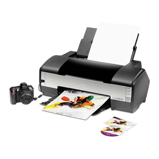
This is a check to ensure your new printer
and drivers are working correctly before the
Eco-Flo System is installed.
It is very important you read these instructions carefully before you begin!
We will take you through the following steps:
1
Preparing your Injector
2
Setting up of the Inks in the bottle tray
3
Installation of the modified injector to your printer
4
Fitting of the Tube Supports System
5
Producing your first print.
Only start work on the installation once you have read the
What you will need to Install the Eco-Flo R1400
*
Complete Eco-Flo R1400 Kit
*
Sharp Blade (Stanley Knife type) & Scissors
*
Measuring Tape or Ruler
*
Marking Pen or Pencil
*
Paper Towels
Please read carefully before you continue and
refer to the components diagram over the
page
ECO-FLO CONTINUOUS INK SYSTEM
Ink System
EPSON PRINTER
instructions fully!
Assembly Instructions for
Epson R1400 Eco-Flo Shown
What is included in your Eco-Flo R1400 Kit
*
Injector Set with tubes attached
*
Set 6 Inks & empty 100ml bottles
*
6 Bottle Caps & clear piping tubes
*
Tube Support Bracket with Self Adhesive
Pads fitted
*
Bottle Holder Tray
*
Special Injector Lid & 2 Chip Blocks
*
1x Grey/White Tube Clip with adhesive pad
*
Installation Instructions and Profiles CD
*
10ml Syringe & wing adaptor
*
Pair of latex gloves
*
6 Tube Clamps
*
Foam Strip
1
PermaJet
R1400
:
Epson R1400
Part No. APJ29421
Advertisement

Related Manuals for Epson R1400


Summary of Contents for Epson R1400
-
Page 1: Ink System
Producing your first print. Only start work on the installation once you have read the instructions fully! What you will need to Install the Eco-Flo R1400 What is included in your Eco-Flo R1400 Kit Complete Eco-Flo R1400 Kit Injector Set with tubes attached Sharp Blade (Stanley Knife type) &... - Page 2 Check List for Components Set of 6 125ml Bottle Caps & Inks Tube Support Clear Piping Bracket Bottle Holder Tray 10ml Syringe Injector Set & Tubes Special Injector 6 Empty 100ml Bottles Wing Adaptor Tube Clip With Pair of Latex Adhesive Pad Gloves 6 Tube...
- Page 3 Check Printer Condition If you have a brand new printer, follow the Epson instructions for setting up your printer. Use the Epson cartridges that came with the printer. Follow normal installation instructions for the software. Test the printer by printing pictures.
- Page 4 INSTALLATION OF YOUR ECO-FLO KIT Step 1 Removing the Injector Lid You will need to remove the printer lid on the injector carrier as shown illustrated from the diagrams below. Store this somewhere safe should you ever wish to return the printer to its original setup. The lid is held in place by two ‘Lugs’...
- Page 5 Step 2 Moving the Printer Head You are now able to move the printer head manually to the centre area of the printer. See below. Fig.6 Step 3 Bottle Preparation Locate the coloured bottle caps and straight lengths of plastic tubes. Insert the straight tube firmly into the bottom of each bottle cap see Fig.7 below.
- Page 6 Step 4 Tube Preparation Using a pair of scissors snip gently at the end of each tube. Please see Fig.8 below. Fig.8 Strip back all the tubes by approx 150mm. Please note when assembling the tubes to the bottle caps you may need to strip back more of the tubing in order for the bottles to be seated correctly within the bottle tray.
- Page 7 Step 6 Positioning the Ink Bottles in The Tray You are now ready to position the ink bottles in the bottle holder tray as indicated below on the LEFT hand side on the same level as the printer. R1400 Setup...
- Page 8 Step 7 Assembling the Tubing to the Bottle Caps When you have completed the above process insert the correct tubes to the correct ink bottles. PLEASE TAKE CARE when doing this as if this is connected incorrectly there is no turning back see Fig.13 & Fig.14 Fig.13 Fig.14 Step 8 Priming the Ink Through the Injectors...
- Page 9 PLEASE ENSURE THAT THE WING ADAPTOR (TIP ONLY) IS GENTLY, BUT MAKES A FIRM SEAL ON THE BASE OF THE INJECTOR, DO NOT push the tip into the injector as this shall split the base of the injector see Fig.16. PLEASE ENSURE that you DOUBLE CHECK that the correct tube is located to the correct ink bottle before pulling back on the syringe (see Fig.17), you may need assistance by another person for the next stage.
- Page 10 Step 9 Installing the Chip Block Unit You are now in a position to remove the Epson cartridges from the printer head, see Fig.20 & Fig.21 below. Fig. 20 Fig. 21 Ensure that you hold the Colour chip block as indicated in Fig.22 and do not touch the contacts as this can cause damage or failure.
- Page 11 Step 10 Installing the Chip Support Bars When you have positioned the chip blocks into place you will need to insert and install the support bars as indicated the correct way up (Arrow up) as illustrated in Fig. 24. Please ensure that you insert the bars as illustrated in Fig.25 making sure that the Groove is on the far end.
- Page 12 Fig.28 Fig.29 Picture shows injectors fully installed in a R1400 Step 12 Fixing the Special Printer Lid Attach the special printer lid that has been supplied making sure that none of the tubing catches or squashes between the lid and housing, as this will stop any ink flowing into the printer heads. At this stage you MUST align the tubes in the correct manner as illustrated in Fig.30.
- Page 13 Align and locate the SLOT in the R1400 printer head as indicated in Fig.32. When you have installed the special printer lid on the R1400 it should finish and look like Fig.33 with the tubes moulded in that position. Slot within the printer head Fig.32...
- Page 14 Step 14 Installing the Central Tube Support Bracket & Aligning the Tubes The Tube Support Bracket has Self Adhesive Strips on it. Use an alcohol or cleaning solution and clean the top of the printer housing where the Tube Support Bracket is going to be attached, see Fig.36. Then make sure the area is dry before proceeding.
- Page 15 Please ensure that the tubing has just enough slack which may need to be adjusted to allow movement of the print head without restriction. This can be done manually by moving the head to the left and right and checking that there is just enough tubing to allow the print head to move freely from left to right, see Fig.39 below.
- Page 16 When you have carefully installed and aligned the tube clip in its correct location, press firmly ensuring that the tube clip is clicked and stuck down to the printer body, as illustrated in Fig.42 below. Fig.42 Step 16 Installing the Foam Strip The purpose of the Foam Strip is to ensure that the tubing on the Eco-Flo travels under the printer body correctly, as well as to cushion the tubes from hitting the printer casing when in motion.
- Page 17 43mm Fig.45 Fig.46 Position the Foam Strip in its correct location as When you have placed the right hand side of indicated in Fig.45, You MUST align the Foam Strip the Foam Strip, very carefully bend it back to the flush to the edge ensuring that you lightly tack white point as illustrated in Fig.46.
- Page 18 OFF, wait for 30 seconds and restart the printer. This process will reset the chips to FULL. A window will open when you make your first print. This informs you that these are not Epson injectors and gives you the option to continue or quit – choose YES and continue printing in the normal way.
- Page 19 Step 18 Removing the Injectors Please note before removing the injectors you MUST clamp the tubing on the relevant injectors by LOCKING the White tube clamps to avoid air traveling up the injector and into the tube. At this point press the ink change button on the front panel of the printer so that you are ready to change or remove the injectors, this function will bring the head unit to the left.
- Page 20 ON THE COMPACT DISC :- THERE IS A CD SUPPLIED WITH YOUR KIT. ON THE CD ARE COPIES OF THE FOLLOWING :- ECO-FLO INSTALLATION INSTRUCTIONS FOR ALL TYPES OF PRINTERS AND SYSTEMS TROUBLE SHOOTING GUIDE INK PURGE TEST FILES AND TONE CHARTS ICC PROFILES FOR USE WITH PERMAJET COLOUR INK AND PAPER COMBINATIONS CURVES FOR USE WITH MONOCHROMEPRO INK SYSTEM.
- Page 21 FAQ»S & Caring For Your Eco-Flo √ READ CAREFULLY!!! Here are some tips to make sure that your new system performs trouble-free. • It is advised to gently shake by rotation each ink bottle on a regular weekly basis. This is to ensure the XL (Xtra Life) Dye inks stay suspended in solution and gives constant results.