Sharp ER-A320 Installation Manual
Hide thumbs
Also See for ER-A320:
- Instruction manual (77 pages) ,
- Programming manual (26 pages) ,
- Service manual (5 pages)
Advertisement
CHAPTER 1. GENERAL .................................................................................... 1
CHAPTER 2. LIST OF OPTIONS ...................................................................... 1
CHAPTER 3. REMOVING THE TOP CABINET ................................................ 2
CHAPTER 4. REMOVING THE PRINTER UNIT ............................................... 3
CHAPTER 5. REMOVING THE MAIN PWB ...................................................... 3
Parts marked with "
" are important for maintaining the safety of the set. Be sure to replace these parts with specified
ones for maintaining the safety and performance of the set.
CONTENTS
SHARP CORPORATION
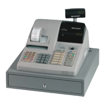
ELECTRONIC
CASH REGISTER
ER-A320
MODEL
SRV Key : LKGIM7113RCZZ
PRINTER : CR-812A
(For "U" version)
This document has been published to be used
for after sales service only.
The contents are subject to change without notice.
Advertisement

Related Manuals for Sharp ER-A320


Summary of Contents for Sharp ER-A320
-
Page 1: Table Of Contents
ELECTRONIC CASH REGISTER ER-A320 MODEL SRV Key : LKGIM7113RCZZ PRINTER : CR-812A (For "U" version) CONTENTS CHAPTER 1. GENERAL ..................1 CHAPTER 2. LIST OF OPTIONS ..............1 CHAPTER 3. REMOVING THE TOP CABINET ..........2 CHAPTER 4. REMOVING THE PRINTER UNIT ..........3 CHAPTER 5. -
Page 2: Chapter 1. General
4) While holding down JOURNAL FEED key, turn from (SRV’) posi- tion to the (SRV) position. Note: 1. The ER-A320 display will flash the "." decimal point at the right most position and will beep 3 times. 2. The ER-A320 printer will cycle and print the following on the journal CHAPTER 2. -
Page 3: Chapter 3. Removing The Top Cabinet
CHAPTER 3. REMOVING THE TOP CABINET 1) Remove the printer cover 5) Remove the transformer cable and the drawer cable from the main PWB. 2) Remove the three screws 3) Remove the screw and grounding wire 4) Separate the top cabinet and the drawer unit. Note: Transformer cable and the drawer cable on the drawer unit are connected to the main PWB on the top cabinet. -
Page 4: Chapter 4. Removing The Printer Unit
CHAPTER 4. REMOVING THE CHAPTER 5. REMOVING THE MAIN PRINTER UNIT 1) Remove the top cabinet. 1) Remove the top cabinet. 2) Remove the printer cable from the main PWB. 2) Remove the printer unit. 3) Remove the three screws 3) Remove the following connector cables from the main PWB. -
Page 5: Chapter 6. Key Top Kit: Er-11Kt7/12Kt7/22Kt7/11Dk7G/51Dk7G
1. Outline Note: There are black spacers and white spacers. Refer to the The ER-A320 employs the following key top (option) to allow additional figure before for attaching them. installation of the key top and change in the key layout. - Page 6 COPYRIGHT 1999 BY SHARP CORPORATION All rights reserved. Printed in Japan. No part of this publication may be reproduced, stored in a retrieval system, or transmitted. In any form or by any means, electronic, mechanical, photocopying, recording, or otherwise, without prior written permission of the publisher.