Table of Contents
Advertisement
DVD PLAYER
DV-454-K
DV-454-S
THIS MANUAL IS APPLICABLE TO THE FOLLOWING MODEL(S) AND TYPE(S).
Model
DV-454-K
WYXU
DV-454-K
WYXU/FRGR
DV-454-K
WVXU
DV-454-S
WYXU
DV-454-S
WYXU/FRGR
DV-454-S
WVXU
Confirm it
Serial No.
For details, refer to "Important symbols for good services".
PIONEER CORPORATION
PIONEER ELECTRONICS (USA) INC. P.O. Box 1760, Long Beach, CA 90801-1760, U.S.A.
PIONEER EUROPE NV Haven 1087, Keetberglaan 1, 9120 Melsele, Belgium
PIONEER ELECTRONICS ASIACENTRE PTE. LTD. 253 Alexandra Road, #04-01, Singapore 159936
PIONEER CORPORATION 2002
STANDBY/ON
Type
Power Requirement
AC220-240V
AC220-240V
AC220-240V
AC220-240V
AC220-240V
AC220-240V
4-1, Meguro 1-chome, Meguro-ku, Tokyo 153-8654, Japan
OPEN/
CLOSE
0
1
¡
3
Î
4
¢
7
8
DV-454-K
Regional restriction
codes (Region No.)
2
2
2
2
2
2
T – ZZE MAY 2002 Printed in Japan
ORDER NO.
RRV2610
Remarks
Advertisement
Table of Contents

Related Manuals for Pioneer DV-454-K


Summary of Contents for Pioneer DV-454-K
-
Page 1: Dvd Player
PIONEER CORPORATION 4-1, Meguro 1-chome, Meguro-ku, Tokyo 153-8654, Japan PIONEER ELECTRONICS (USA) INC. P.O. Box 1760, Long Beach, CA 90801-1760, U.S.A. PIONEER EUROPE NV Haven 1087, Keetberglaan 1, 9120 Melsele, Belgium PIONEER ELECTRONICS ASIACENTRE PTE. LTD. 253 Alexandra Road, #04-01, Singapore 159936 PIONEER CORPORATION 2002 T –... -
Page 2: Safety Information
The interlock mechanism mentioned above becomes invalid in this mode. 2. When the cover is open, close viewing through the objective lens with the naked eye will cause exposure to the laser beam. ∗ : See page 53. DV-454-K... - Page 3 Any disc that displays one of the following logos should play in this player. Other formats, including DVD-Audio, DVD-RAM, DVD-ROM, CD-ROM (except those that contain MP3 files), SACD and Photo CD will not play. DVD-Video Audio-CD Video-CD CD-R CD-RW DV-454-K...
-
Page 4: Table Of Contents
7.1.2 DISPLAY OF THE MECHANISM ERROR HISTORY ................63 7.1.3 TEST POINTS LOCATION & WAVEFORMS ................... 66 7.1.4 TROUBLE SHOOTING ..........................71 7.1.5 SEQUENCE AFTER THE POWER ON ....................73 7.1.6 DISASSEMBLY ............................74 7.2 IC .................................. 79 7.3 CLEANING ..............................97 8. PANEL FACILITIES ............................98 DV-454-K... -
Page 5: Specifications
Audio/Video Cable (L=1.5m): XDE3049 Power Cable [WVXU Type] : ADG1156 White STANDBY/ON OPEN/CLOSE AUDIO SUBTITLE ANGLE CLEAR Yellow ENTER TOP MENU MENU AA/R6P Dry Cell Batteries Power Cable [Other Types] ENTER SETUP RETURN : ADG1154 ¡ ¢ PLAY MODE SURROUND ZOOM DISPLAY DV-454-K... -
Page 6: Exploded Views And Parts List
For the applying amount of lubricants or glue, follow the instructions in this manual. (In the case of no amount instructions, apply as you think it appropriate.) 2.1 PACKING WYXU and WYXU/FRGR Types Only WVXU Type Only WYXU 5, 6, 15, 16 and WYXU/FRGR Types Only "Operating Instructions" DV-454-K... - Page 7 Operating Instructions See Contrast table (2) (English) Accessory Box See Contrast table (2) (2) CONTRAST TABLE DV-454-K/WYXU, WYXU/FRGR, WVXU, DV-454-S/WYXU, WYXU/FRGR and WVXU are constructed the same except for the following : Part No. DV-454-K DV-454-S Mark No. Symbol and Description...
-
Page 8: Exterior Section
2.2 EXTERIOR SECTION Refer to "2.3 LOADING MECHANISM ASSY". NON-CONTACT SIDE CONTACT SIDE 24 24 DV-454-K... - Page 9 See Contrast table (2) Sub Panel See Contrast table (2) Label VRW1872 (2) CONTRAST TABLE DV-454-K/WYXU, WYXU/FRGR, WVXU, DV-454-S/WYXU, WYXU/FRGR and WVXU are constructed the same except for the following : Part No. DV-454-K DV-454-S Mark No. Symbol and Description...
-
Page 10: Loading Mechanism Assy
2.3 LOADING MECHANISM ASSY Note : Refer to Refer to "2.4 TRAVERSE MECHANISM " Application of Lubricant". ASSY-S". To FJMB CN151 Daifree GEM1036 To FJMB CN251 Lubricating Oil GYA1001 Lubricating Oil GYA1001 DV-454-K... - Page 11 Belt VEB1330 Stabilizer VNE2253 Loading Base VNL1917 Float Base DVD VNL1918 Drive Cam VNL1919 Gear Pulley VNL1921 Loading Gear VNL1922 Drive Gear VNL1923 SW Lever VNL1925 Clamper Plate VNE2251 Bridge VNE2252 Clamper VNL1924 Screw JGZ17P028FMC Screw Z39-019 Tray VNL1920 DV-454-K...
- Page 12 GYA1001 Daifree No. 23 Daifree No. 23 GEM1036 Tray GEM1036 Tray Concave of unevenness Concave of unevenness Inner side of a ditch Daifree GEM1036 Bottom View Top View Side of the rib Concave of unevenness Daifree Daifree GEM1036 GEM1036 DV-454-K...
- Page 13 DV-454-K...
-
Page 14: Traverse Mechanism Assy-S
17 (Torque : 0.12 ± 0.01 N•m) Silicone Adhesive GEM1037 Silicone Adhesive GEM1037 4 (Adjustment Screw) (Torque : 0.12 ± 0.01 N•m) Screw Tight Silicone Adhesive GYL1001 GEM1037 17 (Torque : 0.12 ± 0.01 N•m) NON-CONTACT SIDE CONTACT SIDE DV-454-K... - Page 15 VBH1335 Guide Bar VLL1514 Sub Guide Bar VLL1515 Hold Spring VNC1017 Joint Spring VNC1019 Support Spring VNC1020 Mechanism Chassis VNE2248 Slider VNL1811 Spacer VNL1913 Joint VNL1914 FFC Holder VNL1915 Screw BBZ20P050FZK Tapping Screw OBA8009 Screw PMA26P100FMC Damper Sheet VEB1335 DV-454-K...
-
Page 16: Block Diagram And Schematic Diagram
• FL Display Control -28V KEY1 KEY0 FLDC+ FLDC- CN11 (5P) POWER P-CONT SUPPLY KEY0 KEY1 UNIT SW+12V CN301 (5P) EV+4V KEY3 REMOTE J301 RECEIVER (3P) SW+3.3V UNIT IC301 SPS-444L-H (2P) LIVE NEUTRAL IRKY ASSY AC IN PSWB ASSY DV-454-K... -
Page 17: Fjmb Assy
R723 LRCKIN EURO IC301 MM1507XN CN101 JA101 CONNECTOR (20P) V_OUT2 (21P) Y_OUT2 CN901 C_OUT2 (20P) IC401 MM1505XN FRONT_L AUDIO_L AUDIO_L FRONT_R AUDIO_R AUDIO_R G_OUT2 B_OUT2 18 B C403 AUD. LOUT R_OUT2 20 R AUD. ROUT C501 C601 SCRB ASSY DV-454-K... -
Page 18: Power Supply Block
IC303 PQ070XZ02ZP BA18BC0FP V+3R5D V+3R5A V+1RBD V+1RBA1 V+1RBA2 +3.5V Reg. +1.8V Reg. LOAB ASSY VOUT CN601 CN52 V+3D (5P) (5P) V+3R5D IRKY ASSY CN301 CN11 V+3E (5P) (5P) V+3E V+12M V+5V CN901 (20P) CN101 (20P) V+12M V+5V SCRB ASSY DV-454-K... -
Page 19: Waveforms
V: 2V/div. H: 10µsec/div. Foot of C501 (FJMB: IC801 - pin 24, 25) [Video output -G] V: 1V/div. H: 10µsec/div. GND-R(0)→ Foot of C601 (FJMB: IC801 - pin 18, 19) GND-G(-)→ [Video output -B] V: 2V/div. H: 10µsec/div. GND-B(=)→ DV-454-K... -
Page 20: Loab Assy And Overall Wiring Diagram
3.2 LOAB ASSY and OVERALL WIRING DIAGRAM FJMB ASSY (VWS1518) SCRB ASSY (VWV1903) A B C D E DV-454-K... - Page 21 : FOCUS SERVO LOOP LINE for ##XCN type : TRACKING SERVO LOOP LINE : SLIDER SERVO LOOP LINE POWER SUPPLY UNIT (VWR1352 or VWR1354) PICKUP ASSY-S (OXX8003) SPINDLE STEPPING MOTOR MOTOR : VXM1090 : VXX1088 LOAB ASSY LOADING (VWG2279) MOTOR ASSY : VXX2505 DV-454-K...
-
Page 22: Fjmb Assy 1/5 [Front End Block]
3.3 FJMB ASSY 1/5 [FRONT END BLOCK] FJMB ASSY (VWS1518) CN601 STEPPING MOTOR SPINDLE MOTOR DV-454-K... - Page 23 1, 2, #, $: Refer to "3.1.3 WAVEFORMS". : FOCUS SERVO LOOP LINE : TRACKING SERVO LOOP LINE : SLIDER SERVO LOOP LINE VCC33DAC DV-454-K...
-
Page 24: Fjmb Assy 2/5 [Back End Block]
3.4 FJMB ASSY 2/5 [BACK END BLOCK] FJMB ASSY (VWS1518) (S_Y) (S_C) DV-454-K... - Page 25 : V SIGNAL ROUTE (S_C) : S-VIDEO OUT C SIGNAL ROUTE (S_C) (S_Y) : S-VIDEO OUT Y SIGNAL ROUTE : R SIGNAL ROUTE : G SIGNAL ROUTE : B SIGNAL ROUTE : AUDIO SIGNAL ROUTE (S_Y) : AUDIO(DIGITAL) SIGNAL ROUTE DV-454-K...
-
Page 26: Fjmb Assy 3/5 [Audio Block]
3.5 FJMB ASSY 3/5 [AUDIO BLOCK] FJMB ASSY (VWS1518) CN101 DV-454-K... - Page 27 3– 8: Refer to "3.1.3 WAVEFORMS". : AUDIO SIGNAL ROUTE : The power supply is shown with the marked box. DV-454-K...
-
Page 28: Fjmb Assy 4/5 [Video Block]
3.6 FJMB ASSY 4/5 [VIDEO BLOCK] FJMB ASSY (VWS1518) (S_C) (S_C) (S_Y) (S_Y) DV-454-K... - Page 29 : S-VIDEO OUT C SIGNAL ROUTE : B SIGNAL ROUTE (S_Y) : S-VIDEO OUT Y SIGNAL ROUTE : AUDIO SIGNAL ROUTE : R SIGNAL ROUTE : AUDIO(DIGITAL) SIGNAL ROUTE (S_Y) (S_C) (S_C) (S_Y) 9, ~, !: Refer to "3.1.3 WAVEFORMS". DV-454-K...
-
Page 30: Fjmb Assy 5/5 [Fl Control Block]
3.7 FJMB ASSY 5/5 [FL CONTROL BLOCK] FJMB ASSY (VWS1518) (XJ) (XU, XQ) (XCN) DV-454-K... - Page 31 CN601 DV-454-K...
-
Page 32: Irky And Pswb Assys
3.8 IRKY and PSWB ASSYS S301 : 0 OPEN/CLOSE S304 : 7 S302 : 3 S305 : ¡ ¢ S303 : 8 S306 : 4 1 CN11 IRKY ASSY (VWG2344) DV-454-K... - Page 33 VKP2277 S401 : STANDBY/ON PSWB ASSY (VWG2345) for ##XCN type VKP2277 : The power supply is shown with the marked box. DV-454-K...
-
Page 34: Power Supply Unit (Vwr1352)
3.9 POWER SUPPLY UNIT (VWR1352) DV-454-K... -
Page 35: Power Supply Unit (Vwr1354)
3.10 POWER SUPPLY UNIT (VWR1354) DV-454-K... -
Page 36: Scrb Assy
3.11 SCRB ASSY SCRB ASSY(VWV1903) CN901 DV-454-K... - Page 37 : The power supply is shown with the marked box. 0– =: Refer to "3.1.3 WAVEFORMS". DV-454-K...
- Page 38 DV-454-K...
-
Page 39: Pcb Connection Diagram
Transistor B C E SIDE A Transistor with resistor B C E Field effect SIDE B P.C.Board Chip Part transistor Resistor array 3-terminal regulator 4.1 LOAB ASSY LOAB ASSY (VNP1837-B) CN601 CN52 LOADING MOTOR ASSY SIDE A SIDE B DV-454-K... -
Page 40: Fjmb Assy
IC12 R297 C271 R296 R289 Q272 R273 R644 Cross-grain direction FJMB KN901 CN11 CN301 (VNP1867-C) IC351 IC251 Q105 Q103 Q101 IC451 IC302 IC11 IC301 IC304 IC110 Q104 Q102 IC604 IC12 IC271 Q601 IC605 IC303 IC111 IC601 Q271 IC603 Q272 DV-454-K... - Page 41 HEALTH & SAFETY CODE SECTION 25249.2 - PROPOSITION 65 IC441 IC421 Q711 IC771 Q796 Q762 Q768 C604 IC431 Q602 IC711 Q772 IC731 Q761 Q769 C601 Q606 Q604 IC921 Q771 IC901 Q794 Q792 Q791 Q766 Q607 Q603 Q795 Q767 Q605 IC801 Q941 DV-454-K...
- Page 42 KDSPTHRU C945 GNDA KDSPXCS R802 XRESET 44X48 R571 C952 R559 R607 Q808 Q274 R560 Q652 Q807 R582 R805 R670 Q273 R654 Q806 Q805 R668 R666 R283 FJMB R652 Q651 R671 Q776 Q777 Q808 Q807 Q652 Q806 Q805 Q651 Q273 DV-454-K...
- Page 43 R563 R313 R311 R335 R327 R631 R334 R328 R632 R604 R329 R336 V+6B C622 V+3E R570 CN11 -28V FLDC+ FLDC- P-ON XRESET XREADY S(FtoM) S(MtoF) Q274 C272 R291 R286 Q273 Q275 R283 FJMB R282 (VNP1867-C) Q300 Q274 Q273 Q275 DV-454-K...
-
Page 44: Irky And Pswb Assys
S304 IRKY CN301 CN11 SIDE A (VNP1868-B) SIDE B (VNP1868-B) IRKY STOP PLAY PAUSE R311 CMKS-P3X R312 R301 KEY0 VWG2344- R314 R313 KEY1 V+3E R302 IRKY ASSY CLOSE OPEN/ R323 R321 C301 POWER VWG2345- KEY0 CMKS-P3X PSWB PSWB ASSY DV-454-K... -
Page 45: Power Supply Unit (Vwr1352)
4.4 POWER SUPPLY UNIT (VWR1352) SIDE A SIDE A AC IN POWER SUPPLY UNIT Q320 VR201 IC103 IC201 Q412 Q411 Q410 DV-454-K... -
Page 46: Power Supply Unit (Vwr1354)
4.5 POWER SUPPLY UNIT (VWR1354) SIDE A SIDE A AC IN POWER SUPPLY UNIT DV-454-K... -
Page 47: Scrb Assy
14.+12V C101 D401 D501 Q101 D601 C402 D602 R105 D502 C401 D402 R103 C302 R102 C303 R203 Q102 R601 R301 C801 C902 C701 VWV1903- C301 VWV1902- R204 D101 SCRB R109 R206 C103 R205 C203 R902 R901 C901 SCRB ASSY DV-454-K... -
Page 48: Pcb Parts List
IC601 STI5519AVB–B0C IC605 TC7WU04FU IC603 VYW1978 Q300, Q602–Q607, Q762 2SA1037K Q81, Q83 2SA1602A Q103, Q104, Q82, Q941 2SC2412K Q766–Q769 2SD2114K Q652 DTC114TK Q711, Q761, Q805, Q807 DTC114YK Q101, Q102 HN1A01F Q806, Q808 PDTA124EK Q601 RN4982 D601 RB501V–40 D721 UDZS6.2B DV-454-K... - Page 49 R731, R751 RN1/16SE2201D C301 CKSRYF104Z25 R734, R754 RN1/16SE4301D R341 RS1/10S101J RESISTORS R764 RS1/10S182J All Resistors RS1/16S###J R126–R129, R176–R179 RS1/10S220J R254–R259 RS1/10S3R3J OTHERS R822, R832 RS1/10S75R0F R326–R330, R443 RS1/16S1001F 3P CABLE HOLDER 51048–0300 J301 3P JUMPER WIRE D20PDD0315E CN301 CONNECTOR S5B–PH–K DV-454-K...
- Page 50 C403 CEAT100M50 C404, C501, C601 CEAT101M10 C304 CEAT471M6R3 C102, C103, C202, C301–C303 CKSRYF104Z25 C401, C402 CKSRYF104Z25 RESISTORS R301, R401, R501, R601 RS1/10S0R0J R205 RS1/10S68R0F R302, R402, R502, R602 RS1/10S75R0F OtherResistors RS1/16S###J OTHERS CN101 20P CONNECTOR 52045–2045 JA101 CONNECTOR VKB1157 DV-454-K...
-
Page 51: Adjustment
Tangential Radial adjustment adjustment [Electrical Part] screw screw Electrical adjustments are not required. 6.2 JIGS AND MEASURING INSTRUMENTS Test mode remote control Screwdriver (large) Screwdriver (medium) TV monitor unit (GGF1067) Screw tight (GYL1001) DVD test disc Precise screwdriver (GGV1025) DV-454-K... -
Page 52: Necessary Adjustment Points
Purpose: To set the sweep which was correct with the individual Traverse mechanism. Be sure to perform the following step finally when replaced Pickup, Traverse Mechanism and Spindle Motor. CLEAR GGF1067 Test mode remote control unit (It is necessary when performed adjustment procedure Ÿ.) DV-454-K... -
Page 53: Test Mode
Perform only trace, video and audio output are nothing. < When playback with the target address of disc (DVD)> For example, when playback with # 30000 During PLAY CHP/TIM Press keys in order 030000 TEST MODE: OFF POWER GGF1067 Test mode remote control unit DV-454-K... -
Page 54: Mechanism Adjustment
Mechanism Base and turn each screw to adjust the height. (Refer to "6.1 ADJUSTMENT ITEMS AND LOCATION".) Spacer for Height adjustment Note: Turn the Short switch to Short side when Turn a flat side removing the Pickup Flexible Cable. into bottom (Refer to "7.1.6 DISASSEBLY".) DV-454-K... -
Page 55: Dvd Jitter Adjustment
J : Min If error rate is OK, Disc playback normally. locks a root of • The measurement of block error rate tangential and radial adjustment screws with the Screw tight, and go to step Screw tight: GYL1001 Test mode end DV-454-K... - Page 56 Initialize the Focus Sweep Setting Purpose: To set the sweep which was correct with the individual Traverse mechanism. Turn on the Player POWER CLEAR Note: Be sure to perform this step when replaced the Pickup or Traverse mechanism. DV-454-K...
-
Page 57: General Information
Perform only trace, video and audio output are nothing. = Screen display ON/OFF 1. Turn off the display by pressing the [AUDIO] (A8-1E) key of the remote control unit. 2. Turn on the display by pressing the [DISPLAY] (A8-43) key of the remote control unit. DV-454-K... - Page 58 • After the search, perform only trace and video and audio outputs are nothing. 4. Release the Search address input • Clear the address by pressing the [CLEAR] (A8-45) key. Release the address input mode when pressing the [CLEAR] key once again. DV-454-K...
-
Page 59: Display Specification Of The Test Mode
: [NTSC] PAL system : [PAL] Automatic setting : [AUTO] Scart terminal output [SK – ∗ ∗] (Display only the WY model which can do the output setting of scart terminal.) VIDEO : [00] S-VIDEO : [01] : [02] DV-454-K... - Page 60 Change blue and green with toggle whenever pressing the key (the background color that green is using with SETUP NAVIGATOR). • Region confirmation mode Input region No. after pressing the ESC+AUDIO keys. When it is different from the setting, display and open the tray. DV-454-K...
- Page 61 CUT ID / JTAG ID (two columns) (eight columns) 9 B.E VERSION Version of BACK END (version of ST core software) softwareVersion . softwareRevision / buildNumber 0 F.E VERSION Version of FRONT END (version of mechanism controller CHIP software) MainVersion / SubVersion DV-454-K...
-
Page 62: Functional Specification Of The Service Mode
Indicate the mechanism error history by pressing the CHP/TIM key once again. Change indication by pressing the CHP/TIM key with toggle afterwards. Refer to the "Display of the Mechanism Error History". Indication plan contents Character in bold : Item name : Information display DV-454-K... -
Page 63: Display Of The Mechanism Error History
ACQUISITION ERROR 0x8∗ ACQUISITION TIMEOUT 0x9∗ PLL lost error 0x83 PLL lost timeout 0x93 DECODER ERROR 0xa∗ DECODER TIMEOUT 0xb∗ ID lost error 0xa3 ID lost timeout 0xb3 DEVICE ERROR 0xd∗ FAIL SAFE 0xe∗ SRAM error 0xd1 unexpected error 0xe1 DV-454-K... -
Page 64: Error Code Table
Do move to inner and outer periphery 1. Stepping motor of the stepping in the test mode? 2. Inside switch Stepping move timeout 0 x 54 Did timeout at stepping movement Do indicate "S-04" at the most inner 3. Driver periphery of the stepping? DV-454-K... - Page 65 SRAM error 0 x d1 Cannot access SRAM 2. L6315 (Front End IC) Is not bus line short-circuiting? 3. L6315-SRAM bus line FAILSAFE (0 x e∗) 1. software runaway Unexpected error 0 x e1 Unexpected error 3. Software bug DV-454-K...
-
Page 66: Test Points Location & Waveforms
V: 1V/div. H: 10µsec/div. V: 2V/div. H: 500nsec/div. Foot of R721 (IC711 - pin 1) [AUDIO DAC -BCK] V: 2V/div. H: 500nsec/div. Foot of R722 (IC711 - pin 2) [AUDIO DAC -DATA] V: 2V/div. H: 500nsec/div. (Waveform of DATA is unsettled.) DV-454-K... -
Page 67: Video Outputs
Foot of C822 (IC801 - pin 33) [S Video output -C] V: 1V/div. H: 10µsec/div. IC301 - pin 42 [SPDL_PDM] [STOP→PLAY→STOP] [PLAY] [STOP] Accelertar Brakes STOP PLAY STOP V: 2V/div. H: 1sec/div. V: 2V/div. H: 500nsec/div. V: 2V/div. H: 500nsec/div. DV-454-K... - Page 68 SIDE B FCS_RTN CN401 CN951 V: 1 DV-454-K...
- Page 69 IC601 - pin 116 [LOAD_DRV] CN251 - pin 12, 11, 10 V: 1V/div. H: 5µsec/div. (IC251 - pin 2, 4, 7) [Spidle driver -A3, A2, A1] [Tray stops] [Tray is opening] [Tray is closing] [PLAY] V: 2V/div. H: 2msec/div. DV-454-K...
- Page 70 V: 1V/div. H: 10µsec/div. Foot of C501 (FJMB: IC801 - pin 24, 25) [Video output -G] V: 1V/div. H: 10µsec/div. Foot of C601 (FJMB: IC801 - pin 18, 19) [Video output -B] V: 1V/div. H: 10µsec/div. GND-R(0)→ GND-G(-)→ GND-B(=)→ DV-454-K...
-
Page 71: Trouble Shooting
↔ ] H • → • ↔ ] H → L [ ↔ ] H ↔ ] H → ↔ ) n i l y l l " " " " c t i c t i DV-454-K... - Page 72 ± . y l x i f x i f n i l , f f e i l . y l . y l y t i t r i t r i DV-454-K...
-
Page 73: Sequence After The Power On
FL controller outputs the signal which can communicate in BACK END (FP_XRDY) BACK END – FL controller communication The opening picture output FRONT END identifies the following: • Slider positioning (INSIDE SW) • Spindle FG standstill Disc detection (Focus control) Spindle turn DV-454-K... -
Page 74: Disassembly
There is SCRB ASSY instead here. Slit Small Square-bar Screwdriver Protruding portion Drive Gear Loading Mechanism Assy Tray Tray Tray Tray Panel Front Panel Assy Unclamp the wire. Disconnect the wiring. Unhook (×6) Remove the Front Panel. ×3 ×3 Front Panel DV-454-K... - Page 75 Front Panel Assy from Front Panel Assy from Front Panel Assy FJMB Assy FJMB Assy FJMB Assy Put the Power Cable in the outlet. Power ON Set the Test Disc. Playback with a test disc, and diagnose the FJMB Assy. DV-454-K...
- Page 76 Assy Caution in the tray insertion In the Tray insertion, insert it after matching a triangle mark of the Loading Base and a position of pin of the Drive Cam. Loading Base Triangle mark Holder Bottom View Drive Cam DV-454-K...
- Page 77 When Removing The Pickup Assy Screw is locked with Silicone adhesive. Please lock it with Silicone adhesive when installs it. Remove the Pickup Flexible Cable. Silicone Adhesive GEM1037 Slider Hold Spring Pickup Assy Traverse Mechanism Joint Assy Silicone Adhesive GEM1037 Exchange DV-454-K...
- Page 78 Move the Pickup to the innermost of the disc. Perform the styling as shown in figure below. Lose slack Fold position of step Bottom View Bottom View Fold it at the position of reference line. Reference line Bottom View Bottom View DV-454-K...
- Page 79 • The information shown in the list is basic information and may not correspond exactly to that shown in the schematic diagrams. • List of IC M56788AFP, MM1567AJ, STI5519AVB-B0C, PE5314B, L6315ATXXTY, BA6664FM, PCM1742KE 7 M56788AFP (FJMB ASSY : IC351) • FTS Driver IC ¶ Block Diagram DV-454-K...
- Page 80 Luminance input 29 GND2 13 CLP Input clamp select 30 VOUT Signal output 14 CbIN Component input 31 VSAG SAG correction 15 MUTE2 Mute select 32 GND2 16 CrIN Component input 33 COUT Croma output 17 GND2 34 VCC2 DV-454-K...
- Page 81 7 STI5519AVB-B0C (FJMB ASSY : IC601) • Back End IC ¶ Block Diagram DV-454-K...
- Page 82 . r i ) t f n i l . ' L − − y t i & . y l F " − − l a i d i l l a i d i l − − − − DV-454-K...
- Page 83 . r i − − . ) t . ' L . ) t . ) t t ' n . y l . y l . ' L − − − − − DV-454-K...
- Page 84 . r i − − − − − . ) t . ' L . ) t . ' L DV-454-K...
- Page 85 − − − − ' L ' . ) t l l u t s i . ' L ' t i ' L ' − − ' L ' − − − ' L ' ' L ' DV-454-K...
- Page 86 . r i − − − − − − − DV-454-K...
- Page 87 − c i t i t i − c i t i t i " " t i s " " E t i s ) t f ) t f DV-454-K...
- Page 88 L " : " c t i l l o " " " / : " " / " L " : " " " L " / : " L " / " L " : " DV-454-K...
- Page 89 . r i − − − v i t l l o − l l u t s i l l o DV-454-K...
- Page 90 7 L6315ATXXTY (FJMB ASSY : IC301) • Front End IC ¶ Block Diagram DV-454-K...
- Page 91 ¶ Pin Function t l i f n i l n i l i g i d i l t i s DV-454-K...
- Page 92 DV-454-K...
- Page 93 DV-454-K...
- Page 94 DV-454-K...
- Page 95 Control reference pin of output voltage Output pin Output voltage control pin GND pin Power save pin FG signal output pin Power supply pin Gain switching pin Hall signal input pins Motor power pin Resistor connection pin for output current detection Hall bias pin DV-454-K...
- Page 96 DATA 2 4× / 8× Oversampling Enhanced Digital Filter Multi-level with Delta-Sigma Function Modulator Controller ML 15 Serial Control Output Amp and MC 14 Port Low-pass Filter MD 13 System Clock System Clock Power Supply Zero Detect SCK 16 Manager DV-454-K...
-
Page 97: Cleaning
7.3 CLEANING Before shipping out the product, be sure to clean the following positions by using the prescribed cleaning tools: Position to be cleaned Cleaning tools Pickup leneses Cleaning liquid : GEM1004 Cleaning paper : GED-008 DV-454-K... -
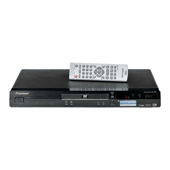
Page 98: Panel Facilities
• Press to jump to the next chapter or track Display 10 4 1 • Press and hold for fast reverse scanning • Press to jump back to the beginning of the Press to start or resume playback current chapter or track, then to previous chapters/tracks DV-454-K... - Page 99 DVD title number 11 3 Lights when a disc is playing Lights when 2V/TruSurround is active 12 2D Lights when a Dolby Digital soundtrack is Indicates that the character display is playing showing a CD or Video CD track number DV-454-K...
-
Page 100: Rear Panel Connections
AV CONNECTOR (RGB) - TV This is a combined audio and video output for connection to a TV that has a SCART input. Connect using a SCART cable. The type of video output can be switched to suit your TV. DV-454-K... -
Page 101: Remote Control
PLAY MODE SURROUND ZOOM DISPLAY Press to start or resume playback 10 4 Press to jump to the beginning of the current chapter or track, then to previous chapters/ tracks 11 8 Press to pause playback; press again to restart DV-454-K... - Page 102 3 (play)) 17 ENTER 23 DISPLAY Use to select menu options, etc. (works Press to display information about the disc exactly the same as the ENTER button in 6 playing above) 24 ZOOM Press to change the zoom level DV-454-K...