Toshiba SD-P2600 Service Manual
Hide thumbs
Also See for SD-P2600:
- Owner's manual (96 pages) ,
- Brochure & specs (2 pages) ,
- Owner's manual (96 pages)
Table of Contents
Advertisement
Quick Links
Download this manual
See also:
Owner's Manual
Advertisement
Table of Contents

Related Manuals for Toshiba SD-P2600


Summary of Contents for Toshiba SD-P2600
-
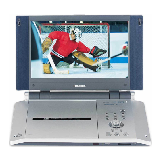
Page 1: Portable Dvd Player
FILE NO. 810-200402 REVISION 1 SERVICE MANUAL PORTABLE DVD PLAYER DOCUMENT CREATED IN JAPAN, Apr., 2004... -
Page 2: Preparation Of Servicing
LASER BEAM CAUTION LABEL When the power supply is being turned on, you may not remove this laser cautions label. If it removes, radiation of laser may be received. PREPARATION OF SERVICING Pickup Head consists of a laser diode that is very susceptible to external static electrocity. Although it operates properly after replacement, if it was subject to electrostatic discharge during replacement, its life might be shortened. -
Page 3: Safty Precautions
SAFTY NOTICE SAFTY PRECAUTIONS LEAKAGE CURRENT CHECK Plug the AC line cord directly into a 120V AC outlet (do Measure the AC voltage across the 1500 resistor. not use an isolation transformer for this check). Use an The test must be conducted with the AC switch on and AC voltmeter, having 5000 per volt or more sensitivity. -
Page 4: Troubleshooting
(Replace the main board, for the trouble could be due to the damage on the main board.) After replacing the main board, special adjustments in TOSHIBA are required. If not, readout of DVD or CD media might not function properly. - Page 5 Adjust the DVD drive. If the drive does not work after the adjustment, the motor portion of the DVD drive or the main board is defective. Replace it. After replacing the DVD drive or the main board, special adjustments in TOSHIBA are required. If not, readout of DVD or CD media might not function properly.
- Page 6 If the image output from the media in the DVD player stops during operation, replace the DVD drive. [Perform pick short of the DVD drive when replacing.] After replacing the DVD drive, special adjustments in TOSHIBA are required. If not, readout of DVD or CD media might not function properly.
- Page 7 Other than the above, disassemble the LCD unit and replace the speakers or the main board. After replacing the main board, special adjustments in TOSHIBA are required. If not, readout of DVD or CD media might not function properly.
- Page 8 2. Caution in Replacing Parts Check whether or not the DVD drive, 42-pin FFC and the main board are connected properly after replacing the DVD drive or the main board. Then, remove the pick protective solder (two points.) Before replacing the DVD drive or the main board, be sure to solder on the DVD drive to prevent damage by static electricity.
- Page 9 Disassembling Reassembling 3.2 Changes in the SD-P2600 (1) SD Card/Multimedia Card slot & Disk cover indication (change1) SD Card/Multimedia Card can be available in SD-P2600 instead of SD Card/Smart Media in SD-P2500. Indication on the disk cover is changed. SD Card/Multimedia Card slot...
- Page 10 (2) LCD cable Holder (change2) In SD-P2600, the LCD cable is fixed with the LCD Cable Holder instead of the insulator in SD- P2500. The following explains how to disassemble and reassemble the LCD Cable Holder. M2x5.0 LCD Cable Holder -Disassembling procedure a) Remove the two screws securing the LCD Cable Holder.
- Page 11 Play a CD-RW or CD-R and check the sound. If pick short of the DVD drive is not removed, the CD- RW or CD-R might not be played. 6. Checking the power-off function Turn off the SD-P2600. 7. Appearance check If you find any dirt or stain, wipe them with soft cloth.
-
Page 12: Block Diagram
5. BLOCK DIAGRAM 27MHz RF AMP 2kb EEPROM DVD audio DVD audio TA1351 2kb EEPROM Buffer Buffer CLK Gen PU Mechanism DSP/ D.A-OUT SD-C2612 ATAPI IF AV-OUT TC9425F AV DECODER Drive MPU C.VIDEO ZR36750 KZ63F49 (FW: Based on SD-P2500 MMC / SD Card slot PUSH-SW unit AV-IN... - Page 13 6. POWER SYSTEM DIAGRAMS SD-P2600 Power Supply Block Diagram 12V(AC Adaptor) Sub MPU E+5V:21mA DC/DC Diodes IR Receiver Others (Battery) VDD+5V1 E+6V MM1665A Filter DVD Drive 97mA/420mA(max) 5V:170mA Filter DVD Circuit 3V:110mA MM1593D DVD Circuit VDD+12V 2.5V:65mA MM1572G DVD Circuit 1.5V...
- Page 14 7. PCB (1/2) S101 PJ701 PJ709 PJ705 S102 PJ401 S102 PJ401 PJ704 PJ703 PJ802 (Front side)
- Page 15 PCB (2/2) F801 F802 PJ706 PJ702 (Back side)
-
Page 17: Parts List
9. PARTS LIST REF No. TOSHIBA SHINCO PART NAME Part No. Part No. AH300683 b30584ps COVER SUB AH300408 21353 SD-P2600 MAIN PCB ASS'Y AH300409 S7483 DAC-05B027 HIGH VOLTAGE PCB ASS'Y AH300273 S1687 TOSHIBA STOP CARD AH300000 S1588 REGULATION CARD (USA) AH300001 S1588a... - Page 18 REF No. TOSHIBA SHINCO PART NAME Part No. Part No. AH300356 b20100 HING-R AH300357 b20139 SHIELD GASKET AH300346 b20124 LCD PLATE AH300347 b20130 LCD PLATE SPONGE AH300687 b20106-1 SIDE-CAP-L AH300688 b20107-1 SIDE-CAP-R AH300689 a2967 SCREW M1.4X3.5 AH300690 a2963 SCREW M1.6X2.5...
- Page 19 TOSHIBA CORPORATION 1-1, SHIBAURA 1-CHOME, MINATO-KU, TOKYO 105-8001, JAPAN...