Sharp AR-M355U Service Manual
Digital multifunctional system
Hide thumbs
Also See for AR-M355U:
- Operation manual (380 pages) ,
- Operation manual (61 pages) ,
- Quick reference manual (33 pages)
Table of Contents
Advertisement
Quick Links
[1] GENERAL. . . . . . . . . . . . . . . . . . . . . . . . . . . . . . . . . . . . . . . . . . . . 1-1
[2] CONFIGURATION . . . . . . . . . . . . . . . . . . . . . . . . . . . . . . . . . . . . . 2-1
[3] SPECIFICATIONS . . . . . . . . . . . . . . . . . . . . . . . . . . . . . . . . . . . . . 3-1
[4] CONSUMABLE PARTS . . . . . . . . . . . . . . . . . . . . . . . . . . . . . . . . . 4-1
[5] EXTERNAL VIEWS AND INTERNAL STRUCTURES . . . . . . . . . . 5-1
[6] UNPACKING AND INSTALLATION . . . . . . . . . . . . . . . . . . . . . . . . 6-1
[7] MAINTENANCE AND DETAILS OF EACH SECTION . . . . . . . . . . 7-1
[8] ADJUSTMENTS . . . . . . . . . . . . . . . . . . . . . . . . . . . . . . . . . . . . . . . 8-1
[9] SIMULATIONS . . . . . . . . . . . . . . . . . . . . . . . . . . . . . . . . . . . . . . . . 9-1
[10] MACHINE OPERATION . . . . . . . . . . . . . . . . . . . . . . . . . . . . . . . . 10-1
[11] TROUBLE CODES . . . . . . . . . . . . . . . . . . . . . . . . . . . . . . . . . . . . 11-1
[12] ROM VERSION-UP METHOD . . . . . . . . . . . . . . . . . . . . . . . . . . . 12-1
[13] ELECTRICAL SECTION. . . . . . . . . . . . . . . . . . . . . . . . . . . . . . . . 13-1
Parts marked with "
" are important for maintaining the safety of the set. Be sure to replace these parts with
specified ones for maintaining the safety and performance of the set.
SERVICE MANUAL
DIGITAL MULTIFUNCTIONAL
SYSTEM
AR-M351U/M451U
AR-M355U/M455U
MODEL
CONTENTS
SHARP CORPORATION
CODE: 00ZARM455UA1E
This document has been published to be used
for after sales service only.
The contents are subject to change without notice.
Advertisement
Table of Contents

Related Manuals for Sharp AR-M355U


Summary of Contents for Sharp AR-M355U
-
Page 1: Service Manual
DIGITAL MULTIFUNCTIONAL SYSTEM AR-M351U/M451U AR-M355U/M455U MODEL CONTENTS [1] GENERAL..........1-1 [2] CONFIGURATION . -
Page 2: Cautions On Laser
CAUTION Cautions on laser +10 nm At the production line, the output power of the scanner unit 785 nm Wave length −15 nm is adjusted to 0.4 MILLIWATT PLUS 8 % and is maintained constant by the operation of the Automatic Power Control (APC). North America: Pulse times 35 cpm model: (6.2 µs ±... -
Page 3: Table Of Contents
Unpacking procedure ......6-2 A. European Subsidiary/East Europe/Russia/ A. AR-M355U/M455U (North America), Australia/New Zealand .....4-1 AR-M351U/M451U (Europe) . - Page 4 [7] MAINTENANCE AND DETAILS OF EACH SECTION [9] SIMULATION [Maintenance System Table] ..... . .7-1 Outline and purpose ......9-1 Engine section .
-
Page 5: General
• Driver's licenses 9) Do not throw toner or a toner cartridge into fire. Toner may be spattered, causing a burn. 10) Store toner or toner cartridges in a hard-to-reach place for chil- dren. AR-M351U/M451U, AR-M355U/M455U GENERAL 1 - 1... -
Page 6: Configuration
• Any one of the upper exit tray extension (AR-TE4), the finisher (AR-FN6), the mail-bin stacker (AR-MS1), or the right upper exit tray (AR-TE5) • AR-EF3 • AR-RK2 * To install the AR-MU2, the exclusive-use desk is required. AR-M351U/M451U, AR-M355U/M455U CONFIGURATION 2 - 1... -
Page 7: B. Option Lineup
12. Mail-bin stacker (AR-MS1) 10. Saddle stitch finisher 13. Fax expansion kit (AR-FN7) (AR-FX12) 4. Multi purpose drawer (AR-MU2) 3. Stand/3 x 500 sheet 2. Stand/MPD & 2000 sheet paper drawer paper drawer (AR-D27) (AR-D28) AR-M351U/M451U, AR-M355U/M455U CONFIGURATION 2 - 2... - Page 8 Bar code font AR-PF1 Flash ROM kit AR-PF2 Cannot be installed together with ❍ ❍ the AR-P21 or the AR-NC8. FAX-related Fax memory (8 MB) AR-MM9 For fax expansion kit (AR-FX12) ❍ ❍ option AR-M351U/M451U, AR-M355U/M455U CONFIGURATION 2 - 3...
-
Page 9: C. List Of Combination Of Peripheral Devices
Data security kit AR-FR22 Data security kit AR-FR22U Data security kit AR-FR21 Data security kit AR-FR21U = Must be installed together. = Any of the units must be installed together. = Cannot be installed together. AR-M351U/M451U, AR-M355U/M455U CONFIGURATION 2 - 4... -
Page 10: Specifications
DSPF: Approx. 46 lb (21 kg) If a printer driver for Windows or Macintosh is used for printing, the printable area will be smaller. The actual printable area depends on the printer driver to be used. AR-M351U/M451U, AR-M355U/M455U SPECIFICATIONS 3 - 1... -
Page 11: B. Document Feeding Equipment
2. Specific Function B5 on B4 Letter on Letter A. Printer Function Ledger on Ledger To enable the printer function of the AR-M355U/M455U, the A4 on A4 printer expansion kit must be installed. A3 on A3 B4 on B4 (1) Platform Binding edge Left / top / right –... - Page 12 Offset cancel Yes/No Tandem print (The AR-P20/P21 or the AR-NC7/NC8 is *1: For printing, PS driver bundled with the Windows is required. required.) Carbon print – Multi- – enlargement XY zoom – – AR-M351U/M451U, AR-M355U/M455U SPECIFICATIONS 3 - 3...
- Page 13 (On OS9, user can select from: No/First Page/Last Page) (*1) Transparency inserts Yes (Blank) Yes (Printed) *1: Since the function is of PS driver bundled with Macintosh, specification may vary according to the OS. AR-M351U/M451U, AR-M355U/M455U SPECIFICATIONS 3 - 4...
-
Page 14: B. Image Send Function
Up to 64-digit (Manual with pause destination entry) Resend This is used to recall the last destination. Speed dialing This is used to recall address control number by using numeric keys. *1: When HDD is installed. AR-M351U/M451U, AR-M355U/M455U SPECIFICATIONS 3 - 5... - Page 15 Program list – Reserved transmit list – Memory box list Yes (FAX mode only) – Memory clear notice list (It's possible that this is output in case of errors.) – Others PC-facsimile PC-iFAX PC-FAX transmission AR-M351U/M451U, AR-M355U/M455U SPECIFICATIONS 3 - 6...
-
Page 16: C. Copy Function
Less than 4.9 Less than 4.4 Tab copy seconds seconds Book copy DSPF Less than 6.0 Less than 5.3 Irregular original size input Yes seconds seconds Irregular paper size input *1: During OC mode AR-M351U/M451U, AR-M355U/M455U SPECIFICATIONS 3 - 7... -
Page 17: B/W Scanner Module (Dspf)
8.5" x 11", 8.5" x 11"R, 5.5" x 8.5" AB-1 A3, B4, A4, A4R, B5, B5R, A5 AB-2 A3, A4, A4R, A5, B5, B5R, 216 x 330 mm AB-3 8K, A4, A4R, A5, B4, 16K, 16KR AR-M351U/M451U, AR-M355U/M455U SPECIFICATIONS 3 - 8... -
Page 18: Rack For Scanner
216 x 330 mm AB-2 A3, B4, A4, A4R, B5, B5R, A5, 8.5" x 11", 11" x 17", 216 x 330 mm AB-3 8K, A4, A4R, B4, 16K, 16KR, 8.5" x 11", 216 x 330 mm AR-M351U/M451U, AR-M355U/M455U SPECIFICATIONS 3 - 9... -
Page 19: Consumable Parts
Toner Cartridge (Black) Toner CA with IC Chip AR-456ST-C *Life : A4 size at Area Coverage (Toner; Net Weight 750g) Developer (Black) Developer 100k AR-455SD-C (Developer; Net Weight 500g) Drum Drum 200k AR-455DR-C AR-M351U/M451U, AR-M355U/M455U CONSUMABLE PARTS 4 - 1... -
Page 20: Maintenance Parts List
Common with cartridge for AR-FN6 Staple cartridge Staple cartridge x 3 5000 times x 3 AR-SC2 Common with cartridge for AR-FN7 Note: The other maintenance parts which are not listed above are registered as service parts. AR-M351U/M451U, AR-M355U/M455U CONSUMABLE PARTS 4 - 2... -
Page 21: C. Hong Kong
Common with cartridge for AR-FN6 Staple cartridge Staple cartridge x 3 5000 times x 3 AR-SC2 Common with cartridge for AR-FN7 Note: The other maintenance parts which are not listed above are registered as service parts. AR-M351U/M451U, AR-M355U/M455U CONSUMABLE PARTS 4 - 3... -
Page 22: Production Number Identification
Numeral figure or X, Y, Z Indicates the production month. X stands for October, Y November, and Z December. Serial No. attachment Temperature (Without dew condensation) Serial No. attachment Heat seal Aluminum bag AR-M351U/M451U, AR-M355U/M455U CONSUMABLE PARTS 4 - 4... -
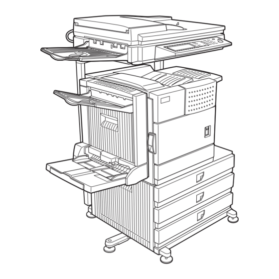
Page 23: External Views And Internal Structures
Up to 500 sheets of 20 lbs. (80 g/m ) paper can be loaded. Also Option special papers such as envelopes (standard sizes only) and (AR-MU2) postcards can be set. AR-M351U/M451U, AR-M355U/M455U EXTERNAL VIEWS AND INTERNAL STRUCTURES 5 - 1... -
Page 24: Interior
Images are formed on the photoconductive drum. NOTE: Do not touch or damage the photoconductive drum. Cartridge lock lever When replacing the drum, toner or developer cartridge, turn down this lever and pull it out. AR-M351U/M451U, AR-M355U/M455U EXTERNAL VIEWS AND INTERNAL STRUCTURES 5 - 2... -
Page 25: Operation Panel
. Use the key to cancel settings and perform an operation from the initial machine state. *1: When the printer expansion kit (with HDD)/print server card (with HDD) is installed. *2: When the network scanner option is installed. *3: When the fax option is installed. AR-M351U/M451U, AR-M355U/M455U EXTERNAL VIEWS AND INTERNAL STRUCTURES 5 - 3... - Page 26 When this key is touched after selecting a job in the COMPLETE job status screen (a job stored using the FILE or QUICK FILE keys of the document filing function), the "JOB SETTINGS" menu screen appears to let you resend or reprint the finished job. AR-M351U/M451U, AR-M355U/M455U EXTERNAL VIEWS AND INTERNAL STRUCTURES 5 - 4...
-
Page 27: Cross Sectional View
Full detection lever Machine tray (Paper tray1) paper feed roller Printer control PWB Machine tray (Paper tray1) separation roller Power supply unit Machine tray (Paper tray1) take-up roller Cleaning roller AR-M351U/M451U, AR-M355U/M455U EXTERNAL VIEWS AND INTERNAL STRUCTURES 5 - 5... -
Page 28: Switch, Sensor
L= Paper detection Toner concentration sensor Paper feed cassette upper limit detection H= Upper limit detection Paper feed cassette paper empty detection L= Paper empty detection MAIN SW Power switch AR-M351U/M451U, AR-M355U/M455U EXTERNAL VIEWS AND INTERNAL STRUCTURES 5 - 6... -
Page 29: A. Scanner Unit
Paper cassette control Drawer PWB Fan control High voltage PWB High voltage power supply Fuse PWB Protection of the machine when an abnormal power is supplied. Relay PWB HDD back up AR-M351U/M451U, AR-M355U/M455U EXTERNAL VIEWS AND INTERNAL STRUCTURES 5 - 7... -
Page 30: Motor, Clutch, Solenoid
Paper cassette paper feed clutch Paper transport clutch PSPS Separation solenoid Resist roller clutch HDDFAN Cooling fan motor (for HDD) Fan motor CNTFAN Cooling fan motor (for controller) Fan motor Polygon motor Polygon motor AR-M351U/M451U, AR-M355U/M455U EXTERNAL VIEWS AND INTERNAL STRUCTURES 5 - 8... -
Page 31: Unpacking And Installation
When installing a controller board, a facsimile unit, and other electric devices, be sure to install them at a time. Only off center adjustment is needed for AR-DU3. For installation of an option unit, refer to the Service Manual of the option unit. AR-M351U/M451U, AR-M355U/M455U UNPACKING AND INSTALLATION 6 - 1... -
Page 32: Note For Installation Place
Operating Manual (Copier/Key Operation) *1 CD-ROM (Printer) *2 – CD-ROM (NIC) Maintenance card/Maintenance case Installation Report/Other Key Sheet (PRINT display) *1 Key Sheet (PRINT display) Key Sheet (DOCUMENT FILING display) Key Sheet (DOCUMENT FILING display) *1 AR-M351U/M451U, AR-M355U/M455U UNPACKING AND INSTALLATION 6 - 2... -
Page 33: Ar-M351U/M451U (Europe))
Front mounting Rear mounting Screws (M4x6): plates: 2 pcs. 4 pcs. plates: 2 pcs. Left adjuster: 1 pc. Left paper guides: 2 pcs. Right paper guides: 2 pcs. AR-M351U/M451U, AR-M355U/M455U UNPACKING AND INSTALLATION 6 - 3... - Page 34 Process the harness cover as shown in the illustration. Screw Caution: For installation of the main unit, it must be held by two persons and installed without haste. Cut out. Harness cover AR-M351U/M451U, AR-M355U/M455U UNPACKING AND INSTALLATION 6 - 4...
-
Page 35: B. Ar-D27
<1> Pull out the paper tray of the main unit until it stops and then Refer to "Setting and adjustment" described later. remove it by lifting both ends of the tray. 8) Carry out the off center adjustment. AR-M351U/M451U, AR-M355U/M455U UNPACKING AND INSTALLATION 6 - 5... - Page 36 I/F connector (white, 4pin) of the main unit. Remove the M4 screw shown in the illustration, insert the cir- cle terminal of ground harness, and it fixes again. Front mounting plate Screw Front mounting plate Screw AR-M351U/M451U, AR-M355U/M455U UNPACKING AND INSTALLATION 6 - 6...
-
Page 37: C. Ar-Mu2
Turn the main switch located on the front side of the main unit to the "OFF" position. Tray frame Then, remove the power plug of the main unit from the outlet. Caution: Insert the mounting plate under the desk frame. "OFF" AR-M351U/M451U, AR-M355U/M455U UNPACKING AND INSTALLATION 6 - 7... - Page 38 PCU PWB of the main unit of the printer. CN10 Connector Multi rear cabinet Screw <2> Remove the two screws that secure the Harness protection sheet. AR-M351U/M451U, AR-M355U/M455U UNPACKING AND INSTALLATION 6 - 8...
- Page 39 7) Adjust the position of the paper guides of the paper tray. Refer to "Setting and adjustment" described later. 2) Attach the rack bottom plate. 8) Carry out the off center adjustment. AR-M351U/M451U, AR-M355U/M455U UNPACKING AND INSTALLATION 6 - 9...
- Page 40 6) Attach the paper exit tray. Attach the paper exit tray to the scanner unit as shown in the figure. Rack Scanner unit Paper exit tray AR-M351U/M451U, AR-M355U/M455U UNPACKING AND INSTALLATION 6 - 10...
-
Page 41: Machine Installing Procedure
1) Remove a new toner cartridge from the package and shake it horizontally five or six times. 3) Remove the top cover of the developer cartridge. 2) Insert a new toner cartridge. Push the cartridge in until it locks securely into place. AR-M351U/M451U, AR-M355U/M455U UNPACKING AND INSTALLATION 6 - 11... -
Page 42: C. Setting Related To Fusing
6) Press the [START] key, and the automatic developer adjust- ment will be performed. During execution of the automatic developer adjustment, “EXECUTING...” is displayed and the toner sensor value is indicated on the LCD. (DEVE REFERENCE) AR-M351U/M451U, AR-M355U/M455U UNPACKING AND INSTALLATION 6 - 12... -
Page 43: Print Test
For one scale (one groove), shift by 0.5mm. display) After shifting the cam, tighten the cam A fixing screw (M3 x 12). Make a copy again and check to confirm that there is no distortion on the image. AR-M351U/M451U, AR-M355U/M455U UNPACKING AND INSTALLATION 6 - 13... -
Page 44: Adjuster Installation And Adjustment
Be sure to install the left adjuster in order to prevent falling down of the machine. Note: If the adjusters are not lowered to the specified positions, the lower stage tray cannot be pulled out. AR-M351U/M451U, AR-M355U/M455U UNPACKING AND INSTALLATION 6 - 14... -
Page 45: Maintenance And Details Of Each Section
Note 1: Replacement reference: Use the counter value of each paper feed port as the replacement reference. Paper feed roller/Separation pad/Torque limiter section (Include Desk, Multi purpose): 100K or 1 years AR-M351U/M451U, AR-M355U/M455U MAINTENANCE AND DETAILS OF EACH SECTION 7 - 1... -
Page 46: Scanner / Dspf
Note 2: Replacement reference: Replace by using the SPF counter value as an indication. Paper feed section pickup roller, paper feed roller, separation pad, separation lower mylar lower: 100K or 1 year AR-M351U/M451U, AR-M355U/M455U MAINTENANCE AND DETAILS OF EACH SECTION 7 - 2... -
Page 47: Peripheral Devices
Note 3: Replacement reference: Use the counter value of each paper feed port as the replacement reference. Paper feed section pickup roller, paper feed roller, separation pad: 100K or 1 year AR-M351U/M451U, AR-M355U/M455U MAINTENANCE AND DETAILS OF EACH SECTION 7 - 3... -
Page 48: Details Of Each Section]
Transfers toner images to the OPC drum. Process drum unit Forms images (electrostatic latent images, visible images) on the OPC drum. Main charger unit Charges the OPC drum surface negatively and evenly. AR-M351U/M451U, AR-M355U/M455U MAINTENANCE AND DETAILS OF EACH SECTION 7 - 4... - Page 49 Bends paper to adjust the paper feed timing to the process section. Paper dust cleaner Removes paper dust from the resist roller to reduce mixing of paper dusts into the process section. AR-M351U/M451U, AR-M355U/M455U MAINTENANCE AND DETAILS OF EACH SECTION 7 - 5...
-
Page 50: Opc Drum Section]
Cleans remaining toner on the OPC drum. Waste toner transport pipe Transports toner from the cleaner unit to the waste toner box in the toner cartridge front section. Cleaning unit Saw teeth charger is cleaned. AR-M351U/M451U, AR-M355U/M455U MAINTENANCE AND DETAILS OF EACH SECTION 7 - 6... - Page 51 OPC drum surface voltage. Electric charges remain at a position where LED lights are not radiated. As a result, latent electrostatic images are formed on the OPC drum surface. AR-M351U/M451U, AR-M355U/M455U MAINTENANCE AND DETAILS OF EACH SECTION 7 - 7...
- Page 52 × Cleaner blade × Side molt F × × Side molt R Separation solenoid 3) Put down the DV guide handle. Loosen the screw, and remove the drum cartridge. AR-M351U/M451U, AR-M355U/M455U MAINTENANCE AND DETAILS OF EACH SECTION 7 - 8...
- Page 53 When installing the toner reception seal, tighten the screw (a) on the positioning side for the first time. Check to confirm that the process earth plate and the toner reception seal are conduc- tive. (10 or less) AR-M351U/M451U, AR-M355U/M455U MAINTENANCE AND DETAILS OF EACH SECTION 7 - 9...
- Page 54 Separation solenoid 3) Remove the toner reception seal. 1) Remove the screw, and remove the rear cabinet. 4) Remove the cleaner blade. 5) Remove the side molt F and R. AR-M351U/M451U, AR-M355U/M455U MAINTENANCE AND DETAILS OF EACH SECTION 7 - 10...
-
Page 55: Transfer Section]
4) Remove the E-ring and the screw, and remove the separation solenoid. [Transfer section] A. General In this section, toner images on the OPC drum are transferred to paper. B. Major parts and signal functions AR-M351U/M451U, AR-M355U/M455U MAINTENANCE AND DETAILS OF EACH SECTION 7 - 11... - Page 56 Separates paper from the drum. TR bearing (F/R) Transfer roller bearing Transfer roller collar Transfer roller collar After-transfer star ring Guides paper after transfer. TR gear Transfer roller drive gear AR-M351U/M451U, AR-M355U/M455U MAINTENANCE AND DETAILS OF EACH SECTION 7 - 12...
- Page 57 PRINTING Job 25 A 45ppm 19 A 31/35ppm 3) After printing 100 sheets (during 1 job) MAX 5KV 200M 1sec 1sec PRINTING (100 Sheets) CLEANING PRINTING (100 Sheets) CLEANING AR-M351U/M451U, AR-M355U/M455U MAINTENANCE AND DETAILS OF EACH SECTION 7 - 13...
- Page 58 TR gear a-1. After-transfer star ring 1) Remove the transfer roller unit. 2) Remove the transfer rear star ring. a. Transfer roller unit 1) Pull out the left door. AR-M351U/M451U, AR-M355U/M455U MAINTENANCE AND DETAILS OF EACH SECTION 7 - 14...
- Page 59 Transfer roller collar a-5. TR bearing (F/R) a-6. TR gear 1) Remove the transfer roller unit. 2) Remove the screw, and remove the discharge plate holder and the discharge plate. AR-M351U/M451U, AR-M355U/M455U MAINTENANCE AND DETAILS OF EACH SECTION 7 - 15...
-
Page 60: Developing Section]
DV doctor Keeps the height of the magnetic brush on the developing roller at a fixed level. Mixing roller (MX roller) Mixes developer (carrier and toner) and charges toner negatively. AR-M351U/M451U, AR-M355U/M455U MAINTENANCE AND DETAILS OF EACH SECTION 7 - 16... - Page 61 OPC drum where negative voltage is reduced by exposure. On the other hand, the negative voltage at an area where expo- sure is not made is higher than the developing bias voltage, and toner is not attached. AR-M351U/M451U, AR-M355U/M455U MAINTENANCE AND DETAILS OF EACH SECTION 7 - 17...
- Page 62 ✕ DV side seal R Toner density sensor Temperature/humidity sensor Toner cartridge Toner motor 3) Put down the DV guide handle, release the lock, and remove the DV cartridge. AR-M351U/M451U, AR-M355U/M455U MAINTENANCE AND DETAILS OF EACH SECTION 7 - 18...
- Page 63 When attaching the SV side seals F and R, attach them to the attachment reference shown in the figure below. 0.5mm 0.5mm Reference Reference 0.5mm 0.5mm Reference Reference a-2. DV blade 1) Remove the DV cartridge. 2) Remove the DV blade. AR-M351U/M451U, AR-M355U/M455U MAINTENANCE AND DETAILS OF EACH SECTION 7 - 19...
- Page 64 3) Remove the connector and the screw, and remove the toner 2) Release the lock and remove the toner cartridge. motor unit. 4) Remove the coupling and the spring from the toner motor. AR-M351U/M451U, AR-M355U/M455U MAINTENANCE AND DETAILS OF EACH SECTION 7 - 20...
-
Page 65: Fusing Section
(NC) +3.3V1 #187(BK) (NC) +3.3V1 B2P4-VH GND2 200V ONLY GND2 9604S-08C DSW-F DSW-F GND2 GND2 +5V2 GND2 MM-T Rth1 Rth2 HLTS 8FE-ST-VK-N DSW-L DSW-L GND1 GND1 +5V2 GND2 MM-T AR-M351U/M451U, AR-M355U/M455U MAINTENANCE AND DETAILS OF EACH SECTION 7 - 21... - Page 66 When the thermostat is opened, power supply (AC line) to the heater lamp is cut off. Fusing roller (Heating) --------- Paper exit Fusing roller (Pressing) AR-M351U/M451U, AR-M355U/M455U MAINTENANCE AND DETAILS OF EACH SECTION 7 - 22...
- Page 67 CL roller ✕ ✕ ✕ ✕ ✕ CL roller bearing ❍ ❍ ❍ ❍ ❍ ❍ ❍ ❍ ❍ Paper guides ✩ ✩ ✩ ✩ ✩ ✩ ✩ ✩ Gears AR-M351U/M451U, AR-M355U/M455U MAINTENANCE AND DETAILS OF EACH SECTION 7 - 23...
- Page 68 1) Pull out the left door. a-2. Upper separation pawl 1) Remove the fusing unit. 2) Remove the rear upper PG, and remove the upper separation pawl. 2) Remove the stopper R. AR-M351U/M451U, AR-M355U/M455U MAINTENANCE AND DETAILS OF EACH SECTION 7 - 24...
- Page 69 ON side) then the screws on the rear side (gear side) in this sequence. Check to confirm again that the screws are tighten securely. (If any screw is loosened, a bad contact may cause heating.) AR-M351U/M451U, AR-M355U/M455U MAINTENANCE AND DETAILS OF EACH SECTION 7 - 25...
-
Page 70: Paper Feed Section
6) Remove the screw, and remove the electrode plate and the thermostat. When installing, check to confirm that the screws are securely tighten again. (If any screw is loosened, a bad contact may cause heating.) AR-M351U/M451U, AR-M355U/M455U MAINTENANCE AND DETAILS OF EACH SECTION 7 - 26... - Page 71 Paper feed tray lift-up motor Drives the lift plate of the paper feed DC brush motor Selection of Rotation tray. mode/ Brake mode Defector Paper empty detection Defector Paper tray upper limit detection AR-M351U/M451U, AR-M355U/M455U MAINTENANCE AND DETAILS OF EACH SECTION 7 - 27...
- Page 72 Monarch 198.0 - 237.0 DBL P/C EX-R 237.0 - 274.0 COM-10 ISO-B5 274.0 - 314.0 Foolscap Extra 314.0 - 347.0 347.0 - 389.0 389.0 - 432.8 Tray not installed AR-M351U/M451U, AR-M355U/M455U MAINTENANCE AND DETAILS OF EACH SECTION 7 - 28...
- Page 73 CSS4 EXTRA 147.0 - 198.0 198.0 - 237.0 EX-R 237.0 - 274.0 274.0 - 314.0 Foolscap EXTRA 314.0 - 347.0 347.0 - 389.0 389.0 - 432.8 Tray not installed AR-M351U/M451U, AR-M355U/M455U MAINTENANCE AND DETAILS OF EACH SECTION 7 - 29...
- Page 74 Paper quantity: 100% Paper quantity sensor: OFF Paper quantity: 66% Paper quantity sensor: ON Paper quantity: 33% Paper quantity sensor: OFF (2nd time) Paper quantity: 0% Paper sensor: OFF AR-M351U/M451U, AR-M355U/M455U MAINTENANCE AND DETAILS OF EACH SECTION 7 - 30...
- Page 75 ✕ Torque limiter Paper feed cassette upper limit detection Paper feed cassette paper empty detection Cassette detection PWB Lift-up motor 2) Disengage the pawl, and remove the paper guide. AR-M351U/M451U, AR-M355U/M455U MAINTENANCE AND DETAILS OF EACH SECTION 7 - 31...
- Page 76 6) Remove the connector, the paper feed cassette upper limit detection, and the paper feed cassette paper empty detection. 2) Remove the connector and the screw, and remove the lift-up motor unit. AR-M351U/M451U, AR-M355U/M455U MAINTENANCE AND DETAILS OF EACH SECTION 7 - 32...
-
Page 77: Transport Section/Paper Exit Reverse Section
OPC drum. Images are transferred onto paper in the transfer section, and the paper is discharged face-up or face-down through the fus- ing section. AR-M351U/M451U, AR-M355U/M455U MAINTENANCE AND DETAILS OF EACH SECTION 7 - 33... - Page 78 Discharges heat generated in the DC brushless PWM control fusing section. motor CFM1 CFM1 Fusing cooling fan motor Discharges heat generated in the DC brushless PWM control fusing section to cool it. motor AR-M351U/M451U, AR-M355U/M455U MAINTENANCE AND DETAILS OF EACH SECTION 7 - 34...
- Page 79 Paper transport path with an option installed Option Model name Desk AR-D27 Duplex unit AR-DU4 Finisher AR-FN6 Option Model name Desk AR-D27 Duplex unit AR-DU3 Finisher AR-FN7 Male bin stacker AR-MS1 Punch unit AR-PN1 AR-M351U/M451U, AR-M355U/M455U MAINTENANCE AND DETAILS OF EACH SECTION 7 - 35...
- Page 80 The AR-FN6 is provided with the decurler to improve alignment capability of finishing. The decurler makes decurling against curling of paper by means of the difference in rigidity of the upper roller (metal) and the lower roller (sponge). Metal Sponge AR-M351U/M451U, AR-M355U/M455U MAINTENANCE AND DETAILS OF EACH SECTION 7 - 36...
- Page 81 Paper exit detection 1 reverse unit Paper exit motor Left door open/close detection Exhaust heat fan motor Paper exit detection 2 Paper exit full detection After-fusing roller Paper exit roller AR-M351U/M451U, AR-M355U/M455U MAINTENANCE AND DETAILS OF EACH SECTION 7 - 37...
- Page 82 High voltage resistor PWB 1) Remove the paper dust cleaner unit. 2) Remove the resist roller unit. 3) Remove the screw, and remove the paper dust cleaner guide. AR-M351U/M451U, AR-M355U/M455U MAINTENANCE AND DETAILS OF EACH SECTION 7 - 38...
- Page 83 3) Remove the screw, and remove the left door transport paper guide. 4) Remove the screw, and remove the angle. 5) Remove the connector, the screw, and remove the drawer PWB. AR-M351U/M451U, AR-M355U/M455U MAINTENANCE AND DETAILS OF EACH SECTION 7 - 39...
- Page 84 5) Remove the screw, and remove the front left upper cabinet. d-1. Paper exit detection 1 1) Remove the paper exit reverse unit. 2) Remove the actuator. Remove the connector, and remove the paper exit detection 1. AR-M351U/M451U, AR-M355U/M455U MAINTENANCE AND DETAILS OF EACH SECTION 7 - 40...
- Page 85 3) Remove the screw, and remove the paper exit upper paper 4) Remove the bearing, the E-ring, and the parts. guide reinforcement plate. 5) Remove the E-ring, and remove the fusing rear roller. Remove the bearing. AR-M351U/M451U, AR-M355U/M455U MAINTENANCE AND DETAILS OF EACH SECTION 7 - 41...
- Page 86 2) Remove the screw, and remove the paper exit upper paper guide unit. 3) Remove the E-ring, and remove the paper exit roller. Remove the bearing, the gear, and the parallel pin. AR-M351U/M451U, AR-M355U/M455U MAINTENANCE AND DETAILS OF EACH SECTION 7 - 42...
-
Page 87: Laser Scanner Section
Clock signal for driving the polygon mirror motor Control signal /START Polygon mirror motor drive start signal Control signal /VIDEO VIDEO (Image signal) Control signal /SYNC Sync signal (SYNC) from BD, sync signal for 1 line AR-M351U/M451U, AR-M355U/M455U MAINTENANCE AND DETAILS OF EACH SECTION 7 - 43... - Page 88 3) Remove the connector, and remove the screw. Sub scan = 75 - 110 m Laser power: 0.23±0.01mW (45 PPM) 0.19±0.01mW (35 PPM) LD wave length: 770 - 795nm D. Maintenance and parts replacement Unit Parts AR-M351U/M451U, AR-M355U/M455U MAINTENANCE AND DETAILS OF EACH SECTION 7 - 44...
- Page 89 7) Release the lock, and pull out the left door. Remove the screw, and remove the front cover right. 11) Remove the screw, and remove the LSU. AR-M351U/M451U, AR-M355U/M455U MAINTENANCE AND DETAILS OF EACH SECTION 7 - 45...
-
Page 90: Scanner Section
The SPF feed a document. The LED light of the CIS unit which is attached to the SPF is radiated to the back of the document, and the document is scanned by the CIS. AR-M351U/M451U, AR-M355U/M455U MAINTENANCE AND DETAILS OF EACH SECTION 7 - 46... - Page 91 Sensor sensor detector Copy lamp Document exposure lamp CCD PWB CCD PWB Front document image scan (Document table/ SPF mode) Converts the document images (optical signals) into electrical signals. AR-M351U/M451U, AR-M355U/M455U MAINTENANCE AND DETAILS OF EACH SECTION 7 - 47...
- Page 92 (analog signal). Auto-focus lens Lens center line LED PWB Glass CIS UNI Focus point AR-M351U/M451U, AR-M355U/M455U MAINTENANCE AND DETAILS OF EACH SECTION 7 - 48...
- Page 93 In the LSU, the VIDEO signals are converted into laser beams, MHPS which are radiated onto the drum. Scan SPF duplex timing chart SPFM 1030mS SRRC SPPD4 94mS SPOD 55mS 181mS AR-M351U/M451U, AR-M355U/M455U MAINTENANCE AND DETAILS OF EACH SECTION 7 - 49...
- Page 94 Mirror home position sensor Scanner control PWB Scanner interface PWB ❍ Lamp unit Reflector ❍ Mirror a-10 Lamp a-11 Inverter PWB CCD lens CCD lens a-13 PWB unit a-12 a-14 AR-M351U/M451U, AR-M355U/M455U MAINTENANCE AND DETAILS OF EACH SECTION 7 - 50...
- Page 95 Scan motor 1) Remove the scanner rear cabinet and the rear lower cabinet. a-5. Mirror 1) Remove the table glass. 2) Clean mirror. AR-M351U/M451U, AR-M355U/M455U MAINTENANCE AND DETAILS OF EACH SECTION 7 - 51...
- Page 96 1) Remove the scanner rear lower cabinet. 2) Disconnect the connector and earth band, and pull out the scanner control PWB. When the scanner control PWB is replaced, the EEPROM must be replaced. AR-M351U/M451U, AR-M355U/M455U MAINTENANCE AND DETAILS OF EACH SECTION 7 - 52...
- Page 97 Note: The CCD lens PWB unit is factory-adjusted before shipping. Since these adjustments cannot be performed in the market. Never touch the screws other than screw 2) of the CCD lens PWB unit. AR-M351U/M451U, AR-M355U/M455U MAINTENANCE AND DETAILS OF EACH SECTION 7 - 53...
-
Page 98: Dspf Section
If this adjustment is not satisfactory, make a fine adjustment with SIM 48-1. (Refer to the adjustment described below.) c-1. CCD lens 1) Remove the table glass. 2) Remove the dark-box cover. 3) Remove the lens cover. AR-M351U/M451U, AR-M355U/M455U MAINTENANCE AND DETAILS OF EACH SECTION 7 - 54... - Page 99 GND2 +5V2 +5V2 /CIS_SET +5V2 +5V2 /CIS_SET SPLS2 SPLS2 GND2 GND2 +24V3 PHNR-2-H+BU2P-TR-P-H /SPFS +24V3 /SPFS SRA-01T-3.2 SRA-21T-3 SRA-21T-3 179228-4+175694-4 B4B-PH-K-S +24V3 +24V3 /STMPS /STMPS /STSET /STSET GND2 GND2 AR-M351U/M451U, AR-M355U/M455U MAINTENANCE AND DETAILS OF EACH SECTION 7 - 55...
- Page 100 After being scanned, the document discharged to the document exit tray by the paper exit roller. The document transport speed varies depending on the scan mode and the scan magnification ratio as shown below. AR-M351U/M451U, AR-M355U/M455U MAINTENANCE AND DETAILS OF EACH SECTION 7 - 56...
- Page 101 Paper exit roller a-11 SPF motor a-12 Resist roller Resist roller clutch SPF original paper feed solenoid SPF original paper feed clutch ❍ Separation mylar lower ❍ Separation pad AR-M351U/M451U, AR-M355U/M455U MAINTENANCE AND DETAILS OF EACH SECTION 7 - 57...
- Page 102 4) Slide the SPF unit to the bottom, then remove it. a-5. SPF control PWB 1) Remove the SPF PWB, and remove the SPF control PWB. a-1. SPF document stopper solenoid 1) Remove the upper transport unit cover. AR-M351U/M451U, AR-M355U/M455U MAINTENANCE AND DETAILS OF EACH SECTION 7 - 58...
- Page 103 3) Remove the hook of each roller, and remove each roller. a-8. SPF original width detection volume PWB 1) Remove the OC cover. 2) Remove the original length sensor cover. 3) Remove the volume cover and remove the volume. AR-M351U/M451U, AR-M355U/M455U MAINTENANCE AND DETAILS OF EACH SECTION 7 - 59...
- Page 104 3) Remove the paper exit frame, and remove the paper exit Note: The CIS unit is factory-adjusted before shipping. roller. Since these adjustments cannot be performed in the market, never touch the following screws of the CIS unit. AR-M351U/M451U, AR-M355U/M455U MAINTENANCE AND DETAILS OF EACH SECTION 7 - 60...
- Page 105 1) Remove the SPF resist roller unit. 3) Remove the original paper feed unit. 2) Remove the SPF resist roller and the SPF resist roller clutch. 4) Remove the SPF drive unit. AR-M351U/M451U, AR-M355U/M455U MAINTENANCE AND DETAILS OF EACH SECTION 7 - 61...
-
Page 106: Operation Panel Section
This section describes various types of settings, display and oper- ation. The LCD display section is controlled by the MFP CONTROL PWB. The touch panel, operation keys and LED display are controlled by the SCANNER CONTROL PWB. AR-M351U/M451U, AR-M355U/M455U MAINTENANCE AND DETAILS OF EACH SECTION 7 - 62... - Page 107 Lcd DIS GND2 GND2 +3.3V +3.3V (NC) (NC) GND2 GND2 (NC) (NC) LCD-VEE LCD-VEE /BZR /BZR /CCFT /CCFT +5V1 +5V1 GND2 GND2 +24V3 +24V3 +24V3 +24V3 GND2 GND2 GND2 GND2 AR-M351U/M451U, AR-M355U/M455U MAINTENANCE AND DETAILS OF EACH SECTION 7 - 63...
- Page 108 Original size detection PWB (Light emitting side) 1) Remove the rear cabinet. 2) Remove the original detection unit (Light emitting side). b. Operation panel unit 1) Remove the original exit tray. AR-M351U/M451U, AR-M355U/M455U MAINTENANCE AND DETAILS OF EACH SECTION 7 - 64...
- Page 109 1) Remove the operation panel unit. 2) Remove the MFP operation PWB 4) Remove the operation panel lower cabinet. 5) Remove the harnesses. 6) Remove the operation panel unit. AR-M351U/M451U, AR-M355U/M455U MAINTENANCE AND DETAILS OF EACH SECTION 7 - 65...
-
Page 110: Filter
Filters Ozone filter (2) Maintenance and parts replacement Unit Parts Ozone filter a-1. Ozone filter 1) Remove the paper exit tray cabinet cover, and remove the ozone filter. AR-M351U/M451U, AR-M355U/M455U MAINTENANCE AND DETAILS OF EACH SECTION 7 - 66... -
Page 111: Drive Section
Parts ✕✩ Drive unit Gears Paper cassette paper feed clutch Paper transport clutch Resist roller clutch Drum motor Main motor 2) Remove the screw, and remove the rear cabinet. AR-M351U/M451U, AR-M355U/M455U MAINTENANCE AND DETAILS OF EACH SECTION 7 - 67... - Page 112 2) Remove the parts. a-1. Gears 1) Remove the main drive unit. 2) Remove the screw, and remove the drive cover. 3) Remove the screw, and remove the drive cover. AR-M351U/M451U, AR-M355U/M455U MAINTENANCE AND DETAILS OF EACH SECTION 7 - 68...
-
Page 113: Power Section
1) Remove the screw, and remove the rear cabinet. 3) Remove the screw, and remove the right noise cover. 2) Remove the connector and the screw, and remove the drum motor and the main motor. AR-M351U/M451U, AR-M355U/M455U MAINTENANCE AND DETAILS OF EACH SECTION 7 - 69... - Page 114 Power PWB 1) Remove the power unit. 2) Remove the connector, the screw, and the PWB supporter, and remove the power PWB. 7) Remove the power unit. AR-M351U/M451U, AR-M355U/M455U MAINTENANCE AND DETAILS OF EACH SECTION 7 - 70...
- Page 115 3) Remove the screw, and remove the cooling fan motor. When installing the fan, check the indication arrow and note the fan direction. AR-M351U/M451U, AR-M355U/M455U MAINTENANCE AND DETAILS OF EACH SECTION 7 - 71...
- Page 116 1) Remove the screw, and pull out the MFP controller PWB unit. 2) Remove the connector. 2) Remove the connector and the screw, and remove the PCU PWB unit. AR-M351U/M451U, AR-M355U/M455U MAINTENANCE AND DETAILS OF EACH SECTION 7 - 72...
- Page 117 6) Remove the screw, and remove the HDD angle. a-2. HDD (Option) 1) Remove the screw, and remove the right cabinet. a-3. PCU PWB 1) Remove the screw, and remove the rear cabinet. AR-M351U/M451U, AR-M355U/M455U MAINTENANCE AND DETAILS OF EACH SECTION 7 - 73...
-
Page 118: Fan Motor
Controller cooling fan motor 1 a-2. Controller cooling fan motor 2 1) Pull out the left door. 9) Remove the screw, and remove the controller box upper. AR-M351U/M451U, AR-M355U/M455U MAINTENANCE AND DETAILS OF EACH SECTION 7 - 74... - Page 119 6) Remove the connector and the screw, and remove the ozone exhaust fan motor. 9) Remove the screw, and remove the cooling fan duct upper. When installing the fan, check the indication arrow and note the fan direction. AR-M351U/M451U, AR-M355U/M455U MAINTENANCE AND DETAILS OF EACH SECTION 7 - 75...
-
Page 120: Adjustments
If the distance is not within the specified range, perform the adjust- figure below. ment in the following procedures. 6) Push the developing doctor in the arrow direction and tighten 8) Loosen the fixing screw of the main pole fixing plate. the fixing screw. AR-M351U/M451U, AR-M355U/M455U ADJUSTMENTS 8 - 1... -
Page 121: C. High Voltage Output Adjustment
FRONT Front 45PPM: +0.22±0.1V 45PPM: 160 0~240 CN2-3 (SIM 8-17) 35PPM: +1.37V±0.1V 35PPM: 120 BACK Rear 45PPM : +0.22±0.1V 45PPM: 160 0~240 35PPM: +1.37V±0.1V 35PPM: 120 Transfer voltage THV -800V±10V 0~1250 CN2-5 (SIM 8-17) AR-M351U/M451U, AR-M355U/M455U ADJUSTMENTS 8 - 2... -
Page 122: Image Check, Adjustment
SPF scan distortion SIM51-2 adjustment Scan magnification ratio SIM48-1 SPF/DSPF scan magnification SIM48-1 ratio Print OC scan lead edge adjustment SIM50-1 lead edge 220mm SPF scan lead edge SIM50-6 adjustment Original off-center adjustment SIM50-12 AR-M351U/M451U, AR-M355U/M455U ADJUSTMENTS 8 - 3... - Page 123 Items which must be executed after completion of this adjust- 7.SPF(HIGH) 8.SPF(LOW) ment. • Print lead edge adjustment • Front/rear and left/right void amount setting 1) Execute SIM 51-2. 2) Enter the resist adjustment value with 10-key. AR-M351U/M451U, AR-M355U/M455U ADJUSTMENTS 8 - 4...
- Page 124 Rear frame void area = 3.5mm (45ppm) for set value 1. If, as shown above, the front and the rear void areas are not even, use SIM 50-5 to adjust the image off-center position. AR-M351U/M451U, AR-M355U/M455U ADJUSTMENTS 8 - 5...
-
Page 125: B. Adjustment On The Scanner Side
Make a copy and check it. If there is any distortion as shown in Fig. 1 or Fig. 2, loosen the scanner fixing screw (M4 x 8) and the cam A fixing screw (M3 x 12) and adjust. AR-M351U/M451U, AR-M355U/M455U ADJUSTMENTS 8 - 6... - Page 126 3) Check that it is in the specified range. 4) If the value is not within the specified range, execute SIM48-1 (item 3, 4). 5) Make a copy again and check again that the value is within the specification. AR-M351U/M451U, AR-M355U/M455U ADJUSTMENTS 8 - 7...
- Page 127 SPF sub scan direction ±0.5% SIM 48-1 Set value 1: magnification ratio (5, 6) 0.1% change SPF (SUB) DSPF main scan (back) direction magnification ratio CIS (MAIN) The SPF main scan direction magnification ratio is common with AR-M351U/M451U, AR-M355U/M455U ADJUSTMENTS 8 - 8...
- Page 128 Back surface lead edge 0 - 99 image loss set value 9 FRONT/REAR Back surface side edge image loss set value 10 TRAIL_EDGE Back surface rear edge 0 - 20 image loss set value AR-M351U/M451U, AR-M355U/M455U ADJUSTMENTS 8 - 9...
-
Page 129: Scanner Section
Angle in the = 90°±0.13° 1 scale = about off-center SPF front output the table 1: 0.1mm distortion above figure 0.25°shift in SIM50-12 SIDE1 surface center line below. shift adjustment adjustment SPF back SIDE2 surface adjustment AR-M351U/M451U, AR-M355U/M455U ADJUSTMENTS 8 - 10... -
Page 130: Adjustment]
Paper exit direction La : Lead edge black background section Lb : Rear edge black background section If La = Lb, the procedures 4) through 7) are not required. AR-M351U/M451U, AR-M355U/M455U ADJUSTMENTS 8 - 11... -
Page 131: Emitting Unit
A3 ORIGINAL ··· COMPLETE (or "ERROR at PD2...") SIMULATION 41-3 <Specification> PD SENSOR DATA DISPLAY. OCSW Specification Adjustment PD1[128]: 200 PD2[128]: 200 Document size detection photo COMPLETE SIM 41-2 PD3[128]: PD4[128]: sensor adjustment PD5[128]: PD6[128]: PD7[128]: AR-M351U/M451U, AR-M355U/M455U ADJUSTMENTS 8 - 12... -
Page 132: H. Image Density Adjustment
2) Place several sheets of A3 (11 x 17) white paper • Copy mode (Sharp’s specified paper) on the test chart at the rear refer- ence. Individual Copy quality mode Collective... -
Page 133: Select 1
• The EEPROM on the MFP control PWB has been replaced. • The scanner control PWB has been replaced. • The EEPROM on the scanner control PWB has been replaced. • One or more parts of the scanner (reading) section have been replaced. AR-M351U/M451U, AR-M355U/M455U ADJUSTMENTS 8 - 14... - Page 134 The Fax mode print density settings for individual Fax modes adjusted through Simulations 46-13, -14, -15, -16 and -45 are changed to the print density level applied by this simulation. AR-M351U/M451U, AR-M355U/M455U ADJUSTMENTS 8 - 15...
- Page 135 (ABOVE +20:DSPF MODE) Select 2, and Press [START] key, or press [START] key. press [CUSTOM SETTINGS] key. SIMULATION 46-13 EXP.LEVEL SETUP FAX(NORMAL). SELECT 3-8, AND PRESS START. (EXP.LEVEL SELECT) 3.AUTO 4.1.0 5.2.0 6.3.0 7.4.0 8.5.0 AR-M351U/M451U, AR-M355U/M455U ADJUSTMENTS 8 - 16...
-
Page 136: I. Dspf Width Detection Adjustment
Press [CUSTOM SETTINGS] key. 4.MIN.POSITION: SIMULATION 53-6 SPF TRAY ADJUSTMENT. Press [START] key. Press [CUSTOM SETTINGS] key. MIN.POSITION ... COMPLETE (or “ERROR”) SIMULATION 53-7 SPF TRAY ADJUSTMENT(MANUAL). INPUT VALUE 0-1023, AND PRESS START. 1.MAX.POSITION AR-M351U/M451U, AR-M355U/M455U ADJUSTMENTS 8 - 17... -
Page 137: Simulations
To cancel the current simulation mode or to change the main code and the sub code, press the user setup key. Canceling the simulation mode to return to the normal mode 1) Press CA key. AR-M351U/M451U, AR-M355U/M455U SIMULATION 9 - 1... - Page 138 Do you want to change the content ? The changed content is stored. Enter the new setting and Press the EXECUTE button adjustment values. and OK button. AR-M351U/M451U, AR-M355U/M455U SIMULATION 9 - 2...
-
Page 139: B. Simulation List
Used to reset the maintenance counter. Used to check the operations of the toner motor Used to reset the developer counter. (The and the related circuit. developer counter of the DV unit which is installed is reset.) AR-M351U/M451U, AR-M355U/M455U SIMULATION 9 - 3... - Page 140 Used to check the operation of sensors and (each ultra fine mode). (Only when FAX is detectors in the paper feed section and the installed.) related circuits. Used to set the gain in shading correction. AR-M351U/M451U, AR-M355U/M455U SIMULATION 9 - 4...
- Page 141 Used to change and check the FAX soft switch position variations are considerably great or when functions. (Used to change and check the paper jams occur frequently.) functions provided for the FAX soft switches.) (Only when FAX is installed) AR-M351U/M451U, AR-M355U/M455U SIMULATION 9 - 5...
- Page 142 (Only when FAX is installed) Used to set YES/NO of the parallel I/F select signal of the printer. Used to check the operation of the network card. AR-M351U/M451U, AR-M355U/M455U SIMULATION 9 - 6...
-
Page 143: C. Details
Optical system home position CISSET CIS installation detection STSET Stamp unit installation sensor SWD_LEN SPF guide plate position (unit: 0.1mm) SIMULATION 1-2 SCANNER SENSOR CHECK.. SWD_AD SPF document width detection volume output AD MHPS value AR-M351U/M451U, AR-M355U/M455U SIMULATION 9 - 7... - Page 144 Punch side register sensor 4 The active sensors and detectors are highlighted. FPDSS3 Punch side register sensor 3 FPDSS2 Punch side register sensor 2 FPDSS1 Punch side register sensor 1 FPTS Punch timing sensor AR-M351U/M451U, AR-M355U/M455U SIMULATION 9 - 8...
- Page 145 Bundle exit motor 2 Saddle folding position 0 - 400 0.0525mm Paddle motor adjustment Transport motor 3 Front alignment position 0 - 20 0.367mm adjustment 4 Rear alignment position 0 - 20 0.367mm adjustment AR-M351U/M451U, AR-M355U/M455U SIMULATION 9 - 9...
- Page 146 MDOPD Interface unit door The active sensors and detectors are highlighted. SIMULATION 3-20 MAIL BOX SENSOR CHECK. MPFD1 MPFD2 MPFD3 MPFD4 MPFD5 MPFD6 MPFD7 MPFD8 MPID MPPD1 MPPD2 MPPD3 MPPD4 MPPD5 M24VM MDD1 MDOPD AR-M351U/M451U, AR-M355U/M455U SIMULATION 9 - 10...
- Page 147 MCPED MP tray paper empty detection TPFD1 MP tray transport detection SIMULATION 4-2 LCC SENSOR CHECK. TDRS TTSD TPFD1 TPFD2 TPFD3 MCLUD TLUD1 TLUD2 MCSPD TSPD1 TSPD2 MCPED TPED1 TPED2 MCSS1 MCSS2 MCSS3 MCSS4 AR-M351U/M451U, AR-M355U/M455U SIMULATION 9 - 11...
- Page 148 Tray 1 lift-up motor TRC_DSK Desk clutch sync signal PSPS Separation pawl solenoid 15*1 MP drive motor control signal 16*1 MCPCL MP tray paper feed clutch signal 17*1 MCFCL MP tray transport clutch signal AR-M351U/M451U, AR-M355U/M455U SIMULATION 9 - 12...
- Page 149 +30:NO PROCESS UNIT CHECK/NO SHADING. SIMULATION 6-2 Press [START] key to start registration and operation. FAN MOTOR CHECK.. The operation mode is kept until the power is turned off or setting is made again. 2.FMLo AR-M351U/M451U, AR-M355U/M455U SIMULATION 9 - 13...
- Page 150 Press [START] key. Press [CUSTOM SETTINGS] key. Warm-up is completed. Press [CUSTOM SETTINGS] key. Or after 30sec output. SIMULATION 7-8 SIMULATION 8-1 WARM UP TIME DISPLAY. WARM UP COMPLETED. DV BIAS SETTING. EXECUTING···. (UNIT:sec) 1:AUTO AR-M351U/M451U, AR-M355U/M455U SIMULATION 9 - 14...
- Page 151 1) Enter the number corresponding to the adjustment item with 2 SHV BACK AC component 0 - 240 10-key. 3 THV- DC component 0 - 1250 2) Press [START] key. 3) Enter the adjustment value with 10-key. AR-M351U/M451U, AR-M355U/M455U SIMULATION 9 - 15...
- Page 152 Press [CUSTOM SETTINGS] key to 2.NO stop the operations. Press [START] key. Press [CUSTOM SETTINGS] key to SIMULATION 9-1 stop the operations. Or after 10sec. ADU OUTPUT CHECK. EXECUTING···. 1.ADMEN1 2.ADMEN2 SIMULATION 10-1 3.DGS TONER MOTOR ACTIVATION. EXECUTING···. AR-M351U/M451U, AR-M355U/M455U SIMULATION 9 - 16...
- Page 153 Without canceling the trouble, the machine returns to the main code entry standby mode. SIMULATION 14 TROUBLE CANCELLATION. (OTHERS) ARE YOU SURE? SIMULATION 16 1. YES U2 TROUBLE CANCELLATION. 2. NO ARE YOU SURE? 1. YES 2. NO AR-M351U/M451U, AR-M355U/M455U SIMULATION 9 - 17...
- Page 154 Number of paper jams DEFAULT SPF JAM Number of SPF jams 1-200: MAINTENANCE CYCLE (1K-200K) TROUBLE Number of troubles 999: FREE SIMULATION 22-2 JAM/TROUBLE COUNTER DATA DISPLAY. PAPER JAM: ******** SPF JAM: ******** TROUBLE: ******** AR-M351U/M451U, AR-M355U/M455U SIMULATION 9 - 18...
- Page 155 FSCID_S Built-in finisher SCID remaining jam paper) PPD1SD1 PPD1 remaining jam (Desk tray 1 feed FSCID2N Built-in finisher SCID2 not-reaching jam paper) FSCID2S Built-in finisher SCID2 remaining jam FPPD_S Built-in finisher PPD remaining jam AR-M351U/M451U, AR-M355U/M455U SIMULATION 9 - 19...
- Page 156 **-**,**-**,**-**,**-**,**-**,**-**,**-**,**-**,**-**,**-**,**-**,**-**,**-** Select 1 and press Press [CUSTOMSETTING] key or **-**,**-**,**-**,**-**,**-**,**-**,**-**,**-**,**-**,**-**,**-**,**-**,**-** [START] key. [START] key. **-**,**-**,**-**,**-**,**-**,**-**,**-**,**-**,**-**,**-**,**-**,**-**,**-** **-**,**-**,**-**,**-**,**-**,**-**,**-**,**-**,**-**,**-**,**-**,**-**,**-** **-**,**-**,**-**,**-**,**-**,**-**,**-**,**-**,**-**,**-**,**-**,**-**,**-** SIMULATION 22-6 ··············· DATA PRINT MODE. EXECUTING···. 0. TRAY SELECT (10 lines, 80 digits = 800 characters) AR-M351U/M451U, AR-M355U/M455U SIMULATION 9 - 20...
- Page 157 PAPER FEED COUNTER DATA DISPLAY. TRAY1: ******** TRAY2: ******** AR-FN6 Built-in finisher installed TRAY3/LCC1:******** TRAY4/LCC2:******** AR-FN7 Console finisher installed BPT: ******** ADU: ******** MAIL BIN ---- Mail bin not installed AR-MS1 Mail bin installed AR-M351U/M451U, AR-M355U/M455U SIMULATION 9 - 21...
- Page 158 Rotating time (sec) FAX SEND Number of FAX send FAX RECEIVE Number of FAX receive FAX OUTPUT Number of FAX print SEND IMAGES Send quantity SEND TIME Send time RECEIVE TIME Receive time AR-M351U/M451U, AR-M355U/M455U SIMULATION 9 - 22...
- Page 159 (PRINT PATTERN) INPUT 1. Item Trouble Operation/Procedure 1) Select "1. PRINT START." 2) Press [START] key. The trouble history of paper jam and misfeed is printed. This data can be cleared by SIM 24-1. AR-M351U/M451U, AR-M355U/M455U SIMULATION 9 - 23...
- Page 160 * = SPF, SCAN, STAPLER, PUNCH, STAMP TRAY1 Tray 1 use quantity TRAY2 Tray 2 use quantity TRAY3/LCC1 Tray 3/LCC left tray use quantity TRAY4/LCC2 Tray 4/LCC right tray use quantity Manual feed tray use quantity Duplex feed quantity AR-M351U/M451U, AR-M355U/M455U SIMULATION 9 - 24...
- Page 161 DEVELOPER COUNTER DATA CLEAR. PRESS START. 1. DV CARTRIDGE Press [START] key. Press [CUSTOM SETTINGS] key or [START] key. SIMULATION 24-5 * COUNTER DATA CLEAR. ARE YOU SURE? 1. YES 2. NO * = DV CARTRIDGE AR-M351U/M451U, AR-M355U/M455U SIMULATION 9 - 25...
- Page 162 The confirmation to clear is opened. 3) Select Yes/NO of counter clear with 10-key. YES: Clear NO: Not clear 4) Press [START] key. DRUM ROTATION OPC drum rotation time DV ROTATION DV unit rotation time AR-M351U/M451U, AR-M355U/M455U SIMULATION 9 - 26...
- Page 163 Press [START] key. Press [CUSTOM SETTINGS] key, and the operation is stopped immediately or after 2 min. SIMULATION 25-1 DV MONITOR. EXECUTING···. HUMIDITY AREA : 70.0 72.5 TEMPERATURE AREA: 70.0 72.5 DEVE REFERENCE : AR-M351U/M451U, AR-M355U/M455U SIMULATION 9 - 27...
- Page 164 INCH Inch series EX VENDOR-EX+ Coin vendor mode (without temporarily JAPAN Japan charge) + Document filing function AB_B AB series B5 enable EUROPE Europe (Default: 1) AUSTRALIA Australia AB_A AB series A5 CHINA China AR-M351U/M451U, AR-M355U/M455U SIMULATION 9 - 28...
- Page 165 Operation mode (Common) Operation/Procedure 1) Select the number corresponding to the operation mode with 10-key. 2) Press [START] key. CE mark control NO (Normal operation) CE mark control YES (Heater lamp soft start operation) AR-M351U/M451U, AR-M355U/M455U SIMULATION 9 - 29...
- Page 166 DISABLING OF U7-00 TROUBLE. SELECT 0-1, AND PRESS START. (Default: 0 for Japan and Australia, 1 for the other) 0. YES 1. NO The target counters are as follows: • Copies counter • Printer counter • Department management counter • Total counter AR-M351U/M451U, AR-M355U/M455U SIMULATION 9 - 30...
- Page 167 The active sensors and detectors are highlighted. size A4/A3, 11 x, B5/B4, 8.5 x , A4R, B5R, A5R, 5.5x, 7.25x, EXTRA SIMULATION 40-1 BYPASS TRAY SENSOR CHECK.. MPLD MPLS1 MPLS2 BYPASS_WIDTH: 2100 BYPASS_AD: (Bypass Tray width size: A4/A3) AR-M351U/M451U, AR-M355U/M455U SIMULATION 9 - 31...
- Page 168 POSITION 2 ··· COMPLETE (or "ERROR") MCSS1 MCSS2 MCSS3 MCSS4 (Multi Purpose Tray width size: A4/A3) Select 4 and press [START] key. Press [CUSTOM SETTINGS] key. SIMULATION 40-2 BYPASS TRAY ADJUSTMENT. MIN. POSITION ··· COMPLETE (or "ERROR") AR-M351U/M451U, AR-M355U/M455U SIMULATION 9 - 32...
- Page 169 No document: Normal display Close: Highlighted sensor status Document present: Highlighted PD1 - 7 PD sensor detection level The value in [ ] indicates the adjustment threshold value (SIM41-2 adjustment SIMULATION 41-1 value). PD SENSOR CHECK.. OCSW AR-M351U/M451U, AR-M355U/M455U SIMULATION 9 - 33...
- Page 170 PROCESS CONTROL VALUE SETTING. INPUT VALUE, AND PRESS Purpose Setting START. 3.S_WT Function Used to set enable/disable of correction (Purpose) operations in the image forming (process) section. Section Image process (Photoconductor/Developing/ Transfer/Cleaning) Item Operation Operation/Procedure When bit =1, correction is made. AR-M351U/M451U, AR-M355U/M455U SIMULATION 9 - 34...
- Page 171 1) Enter 0 with 10-key. INT TEMPERATURE AREA Temperature area in development adjustment 2) Press [START] key. (The mode is changed to the paper feed TARGET LEVEL Toner control reference value tray selection mode.) AR-M351U/M451U, AR-M355U/M455U SIMULATION 9 - 35...
- Page 172 Manual feed NOTE: When [P] key is pressed after entering an adjustment value in this simulation, the adjustment value is set. When START key is pressed, the adjustment value is set and copying is performed. AR-M351U/M451U, AR-M355U/M455U SIMULATION 9 - 36...
- Page 173 Manual feed NOTE: When [P] key is pressed after entering an adjustment value in this simulation, the adjustment value is set. When START key is pressed, the adjustment value is set and copying is performed. AR-M351U/M451U, AR-M355U/M455U SIMULATION 9 - 37...
- Page 174 Manual feed NOTE: When [P] key is pressed after entering an adjustment value in this simulation, the adjustment value is set. When START key is pressed, the adjustment value is set and copying is performed. AR-M351U/M451U, AR-M355U/M455U SIMULATION 9 - 38...
- Page 175 0 - 99 Select 0, and Press [START] key, or press [START] key. press [CUSTOM SETTINGS] key. SIMULATION 46-12 EXP.LEVEL SETUP FAX(AUTO SET).SELECT 1-5, AND PRESS START. (FEED TRAY) 1.TRAY1 2.TRAY2 3.TRAY3 4.TRAY4 5.BPT AR-M351U/M451U, AR-M355U/M455U SIMULATION 9 - 39...
- Page 176 NOTE: When [P] key is pressed after entering an adjustment value in this simulation, the adjustment value is set. When START key is pressed, the adjustment value is set and copying is performed. AR-M351U/M451U, AR-M355U/M455U SIMULATION 9 - 40...
- Page 177 Manual feed NOTE: When [P] key is pressed after entering an adjustment value in this simulation, the adjustment value is set. When START key is pressed, the adjustment value is set and copying is performed. AR-M351U/M451U, AR-M355U/M455U SIMULATION 9 - 41...
- Page 178 Manual feed NOTE: When [P] key is pressed after entering an adjustment value in this simulation, the adjustment value is set. When START key is pressed, the adjustment value is set and copying is performed. AR-M351U/M451U, AR-M355U/M455U SIMULATION 9 - 42...
- Page 179 NOTE: When [P] key is pressed after entering an adjustment value CCD EVEN in this simulation, the adjustment value is set. When START key is pressed, the adjustment value is set and copying is performed. AR-M351U/M451U, AR-M355U/M455U SIMULATION 9 - 43...
- Page 180 12 SPF2_CHARA Text mode (SPF2) 13 SPF2_MIX Text/Photo mode (SPF2) 14 SPF2_PHOTO Photo mode (SPF2) 15 CIS_AE AE mode (CIS) 16 CIS_CHARA Text mode (CIS) 17 CIS_MIX Text/Photo mode (CIS) 18 CIS_PHOTO Photo mode (CIS) AR-M351U/M451U, AR-M355U/M455U SIMULATION 9 - 44...
- Page 181 (Operation setting in the auto copy mode) 1) Select the number corresponding to the mode with 10-key. (Select one of 2 - 4.) 2) Press [START] key. 3) Select the number corresponding to the operation mode with 10-key. AR-M351U/M451U, AR-M355U/M455U SIMULATION 9 - 45...
- Page 182 NOTE: Only the set value is changed and no printing is performed. 4 SPF (EVEN) SPF (front) (even pixel) 5 DSPF DSPF (Back surface) • "Set value - 128" is added to the shading adjustment value (SIM 46-17). AR-M351U/M451U, AR-M355U/M455U SIMULATION 9 - 46...
- Page 183 Select other than 0 - 5, and Press [START] key, or press EXP.LEVEL SETUP SCANNER(FINE). INPUT VALUE 0-99, AND press [START] key. [CUSTOM SETTINGS] key. PRESS START. 0.AUTO SIMULATION 46-22 EXP.LEVEL SETUP SCANNER(NORMAL), INPUT VALUE 0-99, AND PRESS START. 0.AUTO AR-M351U/M451U, AR-M355U/M455U SIMULATION 9 - 47...
- Page 184 [CUSTOM SETTINGS] key. press [START] key. press [CUSTOM SETTINGS] key. SIMULATION 46-25 SIMULATION 46-24 EXP.LEVEL SETUP SCANNER(ULTRA FINE). INPUT VALUE 0-99, EXP.LEVEL SETUP SCANNER(SUPER FINE). INPUT VALUE 0-99, AND PRESS START. AND PRESS START. 0.AUTO 0.AUTO AR-M351U/M451U, AR-M355U/M455U SIMULATION 9 - 48...
- Page 185 10-key. (Select one of 1 - 16.) 2) Press [START] key. (Sharpness adjustment) 1) Enter the sharpness level with 10-key. 2) Press [START] key. The greater the adjustment value is, the greater the sharpness is. AR-M351U/M451U, AR-M355U/M455U SIMULATION 9 - 49...
- Page 186 Exposure level 2 (Half-tone) Set range: 1 - 3 3.0 (H) Exposure level 3 (Half-tone) Default: 3 (Normal), 1 (Halftone) 10 4.0 (H) Exposure level 4 (Half-tone) 11 5.0 (H) Exposure level 5 (Half-tone) AR-M351U/M451U, AR-M355U/M455U SIMULATION 9 - 50...
- Page 187 5 SPF (MAIN) SPF front surface magnification ratio adjustment (Main scan) 6 SPF (SUB) SPF front surface magnification ratio adjustment (Sub scan) 7 CIS (MAIN) SPF back surface magnification ratio adjustment (CIS main scan) AR-M351U/M451U, AR-M355U/M455U SIMULATION 9 - 51...
- Page 188 When the total of the above set value (1 - 5) and 10 is entered, the MIR (55) Mirror motor (55mm/sec) mode is changed to the duplex mode. SPF (220) SPF motor (220mm/sec) SPF (110) SPF motor (110mm/sec) AR-M351U/M451U, AR-M355U/M455U SIMULATION 9 - 52...
-
Page 189: And Press
NOTE: When [P] is pressed after entering an adjustment value, the adjustment value is set. When [START] key is pressed instead, the adjustment value is set and copying is per- Paper lead edge void: 3.5mm (DENA: 35) formed.) AR-M351U/M451U, AR-M355U/M455U SIMULATION 9 - 53... - Page 190 If, as shown above, the front and the rear void areas are not even, press [START] key. press [CUSTOM SETTINGS] key. use SIM 50-5 to adjust the image off-center position. SIMULATION 50-1 LEAD EDGE ADJUSTMENT. (MAGNIFICATION) INPUT 25-400(%) AR-M351U/M451U, AR-M355U/M455U SIMULATION 9 - 54...
- Page 191 25 - 400 (%) below. (Standard set value) Paper lead edge void: 3.5mm (DENA: Set the adjustment value of DENA to 35. Enter 35 as the adjustment value of DENA, and press [P] key. AR-M351U/M451U, AR-M355U/M455U SIMULATION 9 - 55...
- Page 192 7 BPT Manual feed tray LEAD EDGE ADJUSTMENT. SELECT 1-15, AND PRESS START. adjustment (FEED TRAY) 1.TRAY1 2.TRAY2 3.TRAY3 4.TRAY4 8 ADU Adjustment when 5.BPT paper is fed again (ABOVE+10: DUPLEX MODE) from ADU AR-M351U/M451U, AR-M355U/M455U SIMULATION 9 - 56...
-
Page 193: [Start] Key
1) Enter 0 with 10-key. 2) Press [START] key. (The mode is changed to the paper feed tray selection mode.) 3) Enter the number corresponding to the paper feed tray to be used with 10-key. (Table 3) AR-M351U/M451U, AR-M355U/M455U SIMULATION 9 - 57... - Page 194 4) Press [START] key. (The paper feed tray is selected.) To set the copy magnification ratio, perform the following proce- dure. 1) Enter 2 with 10-key. 2) Press [START] key. 3) Enter the copy magnification ratio with 10-key. AR-M351U/M451U, AR-M355U/M455U SIMULATION 9 - 58...
-
Page 195: Set Range Default
0 - 99 4 TRAY2 Tray 2 adjustment 5 TRAY3 Tray 3 adjustment 6 TRAY4 Tray 4 adjustment 7 BPT Manual feed tray adjustment 8 ADU Adjustment when paper is fed again from ADU AR-M351U/M451U, AR-M355U/M455U SIMULATION 9 - 59... - Page 196 2 MAGNIFICATION Print magnification 25 - 400% ratio (Resist adjustment value) 3 PLATEN OC mode 0 - 99 adjustment 4 SPF SIDE1 SPF front surface adjustment 5 SPF SIDE2 SPF back surface adjustment 2) Press [START] key. AR-M351U/M451U, AR-M355U/M455U SIMULATION 9 - 60...
- Page 197 OC side OC (TRAIL_EDGE) OC rear edge SPF (LEAD_EDGE) SPF lead edge SPF (FRONT/REAR) SPF side SPF (TRAIL_EDGE) SPF rear edge CIS (LEAD_EDGE) CIS lead edge CIS (FRONT/REAR) CIS side CIS (TRAIL_EDGE) CIS rear edge AR-M351U/M451U, AR-M355U/M455U SIMULATION 9 - 61...
- Page 198 NOTE: When [P] key is pressed after entering the adjustment value in this simulation, the adjustment value is set. When [START] key is pressed, the adjustment value is set and copying is performed. AR-M351U/M451U, AR-M355U/M455U SIMULATION 9 - 62...
- Page 199 SPF TRAY ADJUSTMENT(MANUAL). INPUT VALUE 0-1023, AND The min. width detection level is recognized. PRESS START. If the above procedures are not completed normally, ERROR is 1.MAX.POSITION displayed. When completed normally, COMPLETE is displayed. AR-M351U/M451U, AR-M355U/M455U SIMULATION 9 - 63...
- Page 200 SCANNER SOFT SW. SETTING. INPUT DATA No(1-8), AND PRESS START. 1 2 3 4 5 6 7 8 SOFT SW-1: SIMULATION 53-8 0 0 0 0 1 0 0 1 SPF SCANNING POSITION ADJUSTMENT. INPUT VALUE 1-70, AND PRESS START. 2. MANUAL AR-M351U/M451U, AR-M355U/M455U SIMULATION 9 - 64...
- Page 201 When read/write is normally completed, "OK" is dis- SRAM. played. If an error occurs, "NG" is displayed. FontROM Transfer from the font ROM to When Flash ROM or OP_Flash ROM is not installed, transfer is not made. 2) Press [START] key. AR-M351U/M451U, AR-M355U/M455U SIMULATION 9 - 65...
- Page 202 76 (AR-M351U/M355U) 93 (AR-M451U/M455U) SIMULATION 61-1 4) Enter [START] key. LSU TEST. ···OK (or NG) 1. LSU NOTE: Be sure to set the default value. If not, a trouble may occur in the LSU. AR-M351U/M451U, AR-M355U/M455U SIMULATION 9 - 66...
- Page 203 Item Clear Operation/Procedure 1) Select YES/NO of hard disk format. Execution Cancel 2) Press [START] key. During formatting, "EXECUTING" is displayed. When formatting is completed normally, "OK" is displayed. If not, "NG" is displayed. AR-M351U/M451U, AR-M355U/M455U SIMULATION 9 - 67...
- Page 204 SMART ERROR LOG PRINT OUT. EXECUTING··· During the self diag operation, "EXECUTING" is displayed. 0. TRAY SELECT If the self diag is completed normally, "0" is displayed. If not, any value but 0 is displayed. AR-M351U/M451U, AR-M355U/M455U SIMULATION 9 - 68...
- Page 205 Press [CUSTOM SETTINGS] key. queues of E-MAIL, FAX and IFAX, reservation data associ- ated with the image send function, bulletin board data, and confidential data. SIMULATION 62-11 DOCUMENT FILING DATA CLEAR. OK. (or NG) AR-M351U/M451U, AR-M355U/M455U SIMULATION 9 - 69...
- Page 206 OC analog level correction and shading correction (Document table mode) DSPF SHADING DSPF analog level correction and shading correction 2) Press [START] key. During execution, "EXECUTING" is displayed. When execution is completed normally, "COMPLETED" is displayed. AR-M351U/M451U, AR-M355U/M455U SIMULATION 9 - 70...
- Page 207 Right oblique 4 by 2 ❍ Right oblique 3 by 3 ❍ Left oblique 2 by 1 ❍ Left oblique 5 by 1 ❍ Left oblique 4 by 2 ❍ Left oblique 3 by 3 AR-M351U/M451U, AR-M355U/M455U SIMULATION 9 - 71...
- Page 208 Note * Toner quantity measuring chart Radiation chart Data printing ❏: Error diffusion process Note*: Since the "DENSITY" of an actual copy or printer output differs, they differ from the output of self print. AR-M351U/M451U, AR-M355U/M455U SIMULATION 9 - 72...
- Page 209 FAX BOX.) Operation/Procedure Setting of soft switches other than SW1 can be changed and checked. 1) Enter the soft switch number to be checked or changed with 10-key. The current set state is displayed. AR-M351U/M451U, AR-M355U/M455U SIMULATION 9 - 73...
- Page 210 32 No RBT No RBT When [CUSTOM SETTINGS] key is pressed during execution, execution is stopped. When a number is entered and [START] key is pressed during execution, the kind of signal can be changed. AR-M351U/M451U, AR-M355U/M455U SIMULATION 9 - 74...
- Page 211 15.2.4 V34 16.14.4 V33 17.12.0 V33 18.14.4 V17 19.12.0 V17 20.9.6 V17 21.7.2 V17 22.9.6 V29 23.7.2 V29 24.4.8 V27t 25.2.4 V27t 26.0.3 FLG 27.CED 2100 28.CNG 1100 29.0.3 V21 30.ANSam 31.RINGER 32.No RBT AR-M351U/M451U, AR-M355U/M455U SIMULATION 9 - 75...
- Page 212 Press [CUSTOM SETTINGS] key. SIMULATION 66-8 MESSAGE OUTPUT CHECK.(LEVEL MAX) SELECT 1-20, AND PRESS START. 1.NONE 2.PAUSE 3.MESSAGE1 4.MESSAGE2 5.MESSAGE3 6.MESSAGE4 7.MESSAGE5 8.MESSAGE6 9.MESSAGE7 10.MESSAGE8 11.MESSAGE9 12.MESSAGE10 13.MESSAGE11 14.MESSAGE12 15.MESSAGE13 16.MESSAGE14 17.MESSAGE15 18.ALARM 19.RINGER 20.EXT.TEL.RINGER AR-M351U/M451U, AR-M355U/M455U SIMULATION 9 - 76...
- Page 213 When [CUSTOM SETTINGS] key is pressed during execution, the START. EXECUTING···. operation is stopped. 1.NONE 2.PAUSE 3.MESSAGE1 4.MESSAGE2 5.MESSAGE3 6.MESSAGE4 7.MESSAGE5 8.MESSAGE6 9.MESSAGE7 10.MESSAGE8 11.MESSAGE9 12.MESSAGE10 13.MESSAGE11 14.MESSAGE12 15.MESSAGE13 16.MESSAGE14 17.MESSAGE15 18.ALARM 19.RINGER 20.EXT.TEL.RINGER Press [CUSTOM SETTINGS] key. AR-M351U/M451U, AR-M355U/M455U SIMULATION 9 - 77...
- Page 214 Used to check troubles in dialing and to check the operation. (Only when FAX is installed) Section Item Operation Operation/Procedure 1) Enter 0 with 10-key. 2) Press [START] key. The dial signal is outputted. AR-M351U/M451U, AR-M355U/M455U SIMULATION 9 - 78...
- Page 215 Execute MAKE TIME Dial pulse make time setting (0 - 15) The dial signal is sent with the set value + 9ms. When [CUSTOM SETTINGS] key is pressed during execution, the operation is stopped. AR-M351U/M451U, AR-M355U/M455U SIMULATION 9 - 79...
- Page 216 Used to check the operation. (Only when FAX is installed) Section Item Operation Operation/Procedure 1) Enter the DTMF signal (1 - 9, 0, *, #) to be sent with 10-key. 2) Press [START] key. AR-M351U/M451U, AR-M355U/M455U SIMULATION 9 - 80...
- Page 217 "COMPLETE" is displayed. FAX INFORMATION PRINT OUT. EXECUTING··· 1. REGISTERED If an error occurs, "FAIL" is displayed. 6) Turn OFF the power, and attach the protect pin. After completion of backup AR-M351U/M451U, AR-M355U/M455U SIMULATION 9 - 81...
- Page 218 1) Enter the Modem dial-in FAX number (1 - 9, 0, *, #) with 10- 1. YES key. 2. NO 2) Press [START] key. SIMULATION 66-25 M-D-IN FAX NUMBER SETTING. 0-9:[0-9],*:[*],#:[#] INPUT NUMBER AND PRESS START. 0123456789*#01234567 AR-M351U/M451U, AR-M355U/M455U SIMULATION 9 - 82...
- Page 219 The result of Modem reload is displayed. Checking completed (OK) COMPLETE Reload completed Checking completed (NG) Check sum error Write error SIMULATION 66-32 Delete error RECEIVED DATA CHECK. Verify error CHECKING···.(OK or NG) Due to loader NG AR-M351U/M451U, AR-M355U/M455U SIMULATION 9 - 83...
- Page 220 Press [START] key. Press [CUSTOM SETTINGS] key. "repeat" and the result is "NG": [CUSTOM SETTINGS] key ON: SIMULATION 66-42 SIMULATION 66-36 PIC PROGRAM RELOAD MFPC-MDMC I/F CHECK. INPUT 1-8, AND PRESS START. EXECUTING...(OK or NG) AR-M351U/M451U, AR-M355U/M455U SIMULATION 9 - 84...
- Page 221 FNET time out 76-255 time 10 fnet_count FNET signal 1-15 settlement number of times 11 poff_time PON signal OFF 0-15 time 12 mswon_level_judge Sense number of 2-15 times until settlement of MSW_ON signal level AR-M351U/M451U, AR-M355U/M455U SIMULATION 9 - 85...
-
Page 222: Simulation
When the printer parallel I/F is used and a trouble is generated in the communication between the PC and the printer, change the setting of this simulation. SIMULATION 67-11 CENTRO SELECT IN SIGNAL SETTING. SELECT 0-1, AND PRESS START. 0. OFF 1. ON AR-M351U/M451U, AR-M355U/M455U SIMULATION 9 - 86... -
Page 223: Other Related Items
Resist amount adjustment value Laser power adjustment value PPD1 sensor adjustment Process correction inhibit allow set value Developing bias rising correction wait time Developing bias rising correction adjustment value Built-in finisher jogger position adjustment Saddle adjustment value AR-M351U/M451U, AR-M355U/M455U SIMULATION 9 - 87... - Page 224 JAM counter Auditor setting Counter mode setting Trouble memory mode setting Center binding mode AMS setting PC/MODEM communication trouble detection YES/NO setting Tag number set value Printers set values Network set value MFP soft SW AR-M351U/M451U, AR-M355U/M455U SIMULATION 9 - 88...
-
Page 225: Machine Operation
Originals with multiple punched holes other than two-hole or three-hole Face down Face down punched paper may not feed correctly. AR-M351U/M451U, AR-M355U/M455U MACHINE OPERATION 10 - 1... -
Page 226: Specifications Of Paper Trays
A5 to A3 5-1/2" x 8-1/2" to 11" x 17" Plain paper 16 to 28 lbs. or 60 to 105g/m² Recycled, colored, pre-punched, pre-printed and letterhead papers must conform to the same conditions as above. AR-M351U/M451U, AR-M355U/M455U MACHINE OPERATION 10 - 2... -
Page 227: B. Applicable Special Paper
• For 5-1/2" x 8-1/2" or A5 paper, the orientation must be landscape. Transparency • Use SHARP recommended paper. Do not use labels other than SHARP recommended labels. film, labels, and Doing so may leave adhesive residue in the machine, causing paper misfeeds, smudges on prints tracing paper or other machine trouble. -
Page 228: Trouble Codes
Finisher 34 Console finisher punch motor With Console installed trouble Finisher Mail-bin stacker With Mail installed communication trouble bin stacker 35 Console finisher punch side With Console installed registration sensor trouble Finisher installed AR-M351U/M451U, AR-M355U/M455U TROUBLE CODES 11 - 1... - Page 229 H2 00 Thermistor open (HL1) trouble feed desk 01 Thermistor open (HL2) installed H3 00 Fusing section high U7 00 RIC communication trouble Controller temperature trouble (HL1) 01 Fusing section high temperature trouble (HL2) AR-M351U/M451U, AR-M355U/M455U TROUBLE CODES 11 - 2...
-
Page 230: Details Of Trouble Codes
Scanner PWB abnormality HDD to the ICU PWB. Check & Check CIS unit harness. Use SIM 62-2, -3 to check read/write of Remedy Check CIS unit. HDD. Check scanner PWB. Replace HDD. Replace ICU PWB. AR-M351U/M451U, AR-M355U/M455U TROUBLE CODES 11 - 3... - Page 231 SPF scanning position communication line. is not detected. Replace the finisher control PWB or Cause Black Mylar installing failure on the PCU PWB. SPF side Check & Check the SPF black Mylar. Remedy AR-M351U/M451U, AR-M355U/M455U TROUBLE CODES 11 - 4...
- Page 232 Gate operation abnormality remedy operation. Cause Gate lock Defective connection or disconnection between the PWB and the solenoid. Mail-bin stacker control PWB trouble Check and Use SIM3-21 to check the transport remedy gate operation. AR-M351U/M451U, AR-M355U/M455U TROUBLE CODES 11 - 5...
- Page 233 Sensor input value abnormality Check and Use SIM3-3 to check the motor Cause Sensor breakage remedy operation. Harness disconnection Console finisher control PWB trouble Check and Use SIM3-2 to check the sensor remedy operation. AR-M351U/M451U, AR-M355U/M455U TROUBLE CODES 11 - 6...
- Page 234 Overcurrent to the motor remedy the connector of the temperature/ Console finisher control PWB trouble humidity sensor. Check and Use SIM3-3 to check the motor Replace the temperature/humidity remedy operation. sensor. Check PCU PWB. AR-M351U/M451U, AR-M355U/M455U TROUBLE CODES 11 - 7...
- Page 235 BOX PWB and that of the machine (set with SIM 26-6). Check and Check the destination of the FAX-BOX. remedy Check the machine destination with SIM 26-6. Use a proper combination of the machine and the FAX-BOX. AR-M351U/M451U, AR-M355U/M455U TROUBLE CODES 11 - 8...
- Page 236 Check scanning with SIM 1-1. Remedy Content Scanner return trouble Details Scanner return is not completed within the specified time. Cause Scanner unit abnormality Scanner wire disconnection Check & Check scanning with SIM 1-1. Remedy AR-M351U/M451U, AR-M355U/M455U TROUBLE CODES 11 - 9...
- Page 237 Check and Check that EEPROM is properly Check connector and harness remedy inserted. connection. Save the counter/adjustment values Replace LSU. with the simulation. Use SIM16 to cancel U2 trouble. Replace the ICU PWB. AR-M351U/M451U, AR-M355U/M455U TROUBLE CODES 11 - 10...
- Page 238 Hang of control circuit due to noises Check and Check that EEPROM is properly remedy inserted. Save the counter/adjustment values with the simulation. Use SIM16 to cancel U2 trouble. Replace the Controller PWB. AR-M351U/M451U, AR-M355U/M455U TROUBLE CODES 11 - 11...
- Page 239 Desk control PWB trouble remedy installed on the controller. Check and Use SIM4-3 to check the transport 2. Output the NIC Config. Page to remedy motor operation. check the NIC version. 3. Replace the NIC. AR-M351U/M451U, AR-M355U/M455U TROUBLE CODES 11 - 12...
- Page 240 FTP server registered as the destination. Check and 1. Check that the network cable is remedy properly connected. 2. Check for existence of the directory name in the FTP server registered as the destination. AR-M351U/M451U, AR-M355U/M455U TROUBLE CODES 11 - 13...
-
Page 241: Simulation
(test commands). Trouble cancel command Trouble code Storing simulation Reset H3, H4, H5 SIM 14 SIM 13 Standby state Each block SIM 16 SIM 17 U6-2, 3 SIM 15 AR-M351U/M451U, AR-M355U/M455U TROUBLE CODES 11 - 14... - Page 242 5: When detected except in a job, can be operated except in the trouble paper exit section. 6: When detected except in a job, can be operated in the single surface scan mode. AR-M351U/M451U, AR-M355U/M455U TROUBLE CODES 11 - 15...
-
Page 243: Simulation
(SIMULATION. 26-35) 0: A same trouble as the previous one is not written. (Default) 1: Any trouble is written into the trouble memory unconditionally. AR-M351U/M451U, AR-M355U/M455U TROUBLE CODES 11 - 16... -
Page 244: Rom Version-Up Method
MENU key OK key ON the back of the machine, there are following DIP switches from the controller PWB: • Diag mode switch (on the left) • Write protect switch (on the right) AR-M351U/M451U, AR-M355U/M455U ROM VERSION-UP METHOD 12 - 1... - Page 245 (Use Up/Down key to check on the window of 1).) 8) Turn off the power, and reset the DIP switches to the upper side (protect side, normal side). AR-M351U/M451U, AR-M355U/M455U ROM VERSION-UP METHOD 12 - 2...
-
Page 246: D. In Case Of "Result: Ng"
Turn off the power and replace the ROM’s with the spare one of the PCU and the scanner ROM, and perform the update procedure of (C.) for the replaced ROM’s. Be sure to set the DIP switches properly. AR-M351U/M451U, AR-M355U/M455U ROM VERSION-UP METHOD 12 - 3... - Page 247 (B.) replace it with a spare. Result: OK ? Writing by CN6 of the Update completed controller PWB (C.) Result: OK ? Update completed ROM trouble? Replace the ROM and retry. AR-M351U/M451U, AR-M355U/M455U ROM VERSION-UP METHOD 12 - 4...
- Page 248 5) The driver of SHARP AR-M455N is automatically installed. (1) File transfer by Fcopy.EXE (Note that the model name is displayed as SHARP AR-M455N For file transfer by Fcopy, put Fcopy.exe and the files in a same regardless of the actual model name.) directory, and boot the MS-DOS.
-
Page 249: Electrical Section
[13] ELECTRICAL SECTION 1. Block diagram AR-M351U/M451U, AR-M355U/M455U ELECTRICAL SECTION 13 - 1... -
Page 250: Actual Wiring Chart
GND2 +10V +10VCCD GND2 +10V +10VCCD /CL1 GND2 GND2 PDSEL0 GND2 GND2 +5V2 SEG1 SEG2 GND2 GND2 GND2 GND2 GND2 /BZR GND2 +5V1 Lcd DIS +3.3V GND2 LCD-VEE /CCFT +24V3 +24V3 GND2 GND2 AR-M351U/M451U, AR-M355U/M455U ELECTRICAL SECTION 13 - 2... - Page 251 GND2 +24V3 +24V3 GND2 GND2 GND2 +24V3 +24V3 GND2 GND2 GND2 +24V3 +24V3 GND2 GND2 GND2 /BZR GND2 GND2 GND2 +5V1 GND2 Lcd DIS GND2 +3.3V GND2 LCD-VEE /CCFT +24V3 +24V3 GND2 GND2 AR-M351U/M451U, AR-M355U/M455U ELECTRICAL SECTION 13 - 3...
- Page 252 (NC) (NC) (NC) (NC) /BZR /BZR +5V1 +5V1 GND2 GND2 SLD5R-1 SLD5S-1 GND2 GND2 GND2 GND2 /CL1 /CL1 +24V3 +24V3 +24V3 +24V3 179228-4+175694-4 B4B-PH-K-S +24V3 +24V3 /STMPS /STMPS STMP /STSET /STSET GND2 GND2 AR-M351U/M451U, AR-M355U/M455U ELECTRICAL SECTION 13 - 4...
- Page 253 /CV_COUNT (2/3) /CV_START /CV_CA /CV_STAPLE /CV_DUPLEX /CV_SIZE0 /CV_SIZE1 /CV_SIZE2 /CV_SIZE3 B13B-PH-K-S PHR-13 /PNC /COPY /READY /AUD +5V2 GND2 +24V3 (NC) +24V3 PNC_a GND2 CN11 S3B-PH-K-S 53053-0310(MOLEX) MHPS MHPS MHPS GND2 GND2 +5V2 +5V2 AR-M351U/M451U, AR-M355U/M455U ELECTRICAL SECTION 13 - 5...
- Page 254 SMR-03V-NC+SMP-03V-N VAREF SPFVR SPWS GND2 B12B-PHDSS-B 1754873+179228-3 VAREF +5V2 SPWS SPLS1 SPLS1 GND2 GND2 +5V2 SPLS1 1754873+179228-3 GND2 +5V2 +5V2 SPLS2 SPLS2 SPLS2 GND2 GND2 +24V3 PHNR-2-H+BU2P-TR-P-H /SPFS +24V3 SPFS /SPFS SRA-01T-3.2 SRA-21T-3 AR-M351U/M451U, AR-M355U/M455U ELECTRICAL SECTION 13 - 6...
- Page 255 B12B-PHDSS-B TXD_CCD2 TXD_CCD2 RES_CCD2 RES_CCD2 RXD_CCD2 RXD_CCD2 +3.3V +3.3V +3.3V +3.3V +24V3 +24V3 GND2 GND2 +12V1 +12V1 GND2 /LST GND2 +5V2 SCLK +5V2 GND2 GND2 GND2 +5V2 GND2 +5V2 /CIS_SET /CIS_SET (3/3) SRA-21T-3 AR-M351U/M451U, AR-M355U/M455U ELECTRICAL SECTION 13 - 7...
- Page 256 +12V_FAN HDD-MON +5V1 +5V1 GND2 +5V1 +5V1 CFM-PWM +5V1 +5V1 +12V_FAN +5V2 +5V2 +5V2 +5V2 HDD-MON GND2 FM_HDD +24V3 +24V3 CFM-PWM +24V3 +24V3 4 +12V_FAN +12V1 +12V1 HDD-MON GND2 FM_CNT 3 CFM-PWM +12V_FAN AR-M351U/M451U, AR-M355U/M455U ELECTRICAL SECTION 13 - 8...
-
Page 257: Lsu Unit
+24V1 S4B-PH-K-S B4B-PH-K-S /VFM1 /VFM1 GND2 GND2 GND2 GND2 SYNC\ SYNC\ /START /START GND2 GND2 /VFM1 /VFM1 +5V2 +5V2 /PMCLK /PMCLK /READY /READY GND2 GND2 GND2 GND2 +5V LD +5V LD GND2 GND2 AR-M351U/M451U, AR-M355U/M455U ELECTRICAL SECTION 13 - 9... -
Page 258: Toner Hopper
HUS-DV +5V2 HUS-DV DVBias HUS-DV +24V1 GND2 #187 GND2 TH-DV Bias RRC\ SRA-21T-3 Bias +24V1 +5V2 TRC\ GND2 GND2 PPD1 LUMB +5V2 LUMA CFM1\ GND2 +24V1 CN22 GND2 SHORT JIG 173981-2 PCU_RES GND2 AR-M351U/M451U, AR-M355U/M455U ELECTRICAL SECTION 13 - 10... -
Page 259: Main Drive
GND2 +5V2 179228-3(AMP) GND2 +5V2 GND2 CASETTE UNIT CSS PWB S4B-PH-K-S GND2 173979-2 173979-2 LUMB LUMB LUMB LUMA LUMA LUMA PHNR-02-H+BU02P-TR-P-H CPFC\ CPFC +24V1 PHNR-02-H+BU02P-TR-P-H RRC\ MAIN DRIVE +24V1 PHNR-03-H+BU03P-TR-P-H TRC1\ (NC) +24V1 AR-M351U/M451U, AR-M355U/M455U ELECTRICAL SECTION 13 - 11... -
Page 260: Fusing Unit
Lout #250(YL) Nout ELP-02V+ELR-02VF DH-L DH-N to HDD to DESK UN (N model SIN-21T-1.8S DH-L SIN-21T-1.8S DH-N AC IN INLET VLR-06V+VLP-06V-1 POWER LFin B03P-VL YL/GR YL/GR (NC) LFout NFin YL/GR YL/GR NFout DCPR AR-M351U/M451U, AR-M355U/M455U ELECTRICAL SECTION 13 - 12... - Page 261 ELR-04NVF +5VOPT +24V4 GND2 GND2 to DESK UN Mother PWB ELP-06V-NV+ELR-06N V9PS-VH +5V1 +5V1 +5V1 +5V1 +24V3 +24V3 DCCNT DCCNT (NC) +12V GND2 GND2 +12V HDD-VCC GND2 GND2 HDD-VCC LCP-04 del only) DCPS AR-M351U/M451U, AR-M355U/M455U ELECTRICAL SECTION 13 - 13...
- Page 262 Lout #250(YL) ELP-02V+ELR-02VF Nout DH-L DH-N to HDD to DESK UN (N model SIN-21T-1.8S DH-L SIN-21T-1.8S AC IN DH-N INLET VLR-06V+VLP-06V-1 B03P-VL LFin POWER YL/GR YL/GR (NC) LFout NFin YL/GR YL/GR NFout DCPR AR-M351U/M451U, AR-M355U/M455U ELECTRICAL SECTION 13 - 14...
- Page 263 ELR-04NVF +5VOPT +24V4 GND2 GND2 to DESK UN Mother PWB ELP-06V-NV+ELR-06N V9PS-VH +5V1 +5V1 +5V1 +5V1 +24V3 +24V3 DCCNT DCCNT (NC) +12V GND2 GND2 HDD-VCC +12V GND2 GND2 HDD-VCC LCP-04 del only) DCPS AR-M351U/M451U, AR-M355U/M455U ELECTRICAL SECTION 13 - 15...
- Page 264 DCPR\ ADM H/L ADUFM\ MPLS2 MPLS1 (NC) (NC) CN11 B22B-PADRS(RED) TXD-FIN1 RXD-FIN1\ DTR-FIN1\ DSR-FIN1\ RES-FIN1 GND2 TXD-FIN2 RXD-FIN2\ DTR-FIN2\ DSR-FIN2\ DESK RES-FIN2 GND2 TXD-DSK RXD-DSK\ DTR-DSK\ DSR-DSK\ RES-DSK TRC-DSK\ FGS-FIN\ FM1\ DCPR\ +24V2 AR-M351U/M451U, AR-M355U/M455U ELECTRICAL SECTION 13 - 16...
- Page 265 OPTION (1/1) AR-M351U/M451U, AR-M355U/M455U ELECTRICAL SECTION 13 - 17...
- Page 266 DH-LINE (OPTION) (1/1) AR-M351U/M451U, AR-M355U/M455U ELECTRICAL SECTION 13 - 18...
-
Page 267: Signal Name List
Paper tray upper limit — Upper limit detection signal detection LUMA Paper tray lift-up motor Paper tray lift-up control Stop control signal LUMB Paper tray lift-up motor Paper tray lift-up control Stop control signal AR-M351U/M451U, AR-M355U/M455U ELECTRICAL SECTION 13 - 19... - Page 268 The controller resets the Operation Reset PCU. enable RTH1 Fusing roller temperature Fusing roller temperature — — detection signal detection (Center section) RTH2 Fusing roller temperature Fusing roller temperature — — detection signal detection (Edge section) AR-M351U/M451U, AR-M355U/M455U ELECTRICAL SECTION 13 - 20...
- Page 269 Receive control — — control signal XDSR_FIN1 Serial communication Receive control — — control signal XDSR_FIN2 Serial communication Receive control — — control signal XDTR_DSK Serial communication Send control — — control signal AR-M351U/M451U, AR-M355U/M455U ELECTRICAL SECTION 13 - 21...
- Page 270 — detection XRRC Resist roller clutch control Resist roller clutch ON/ Paper — signal OFF control transport XRSVOUT2 Reserved Reserved — — XSTART Polygon mirror motor drive Polygon mirror motor start signal control AR-M351U/M451U, AR-M355U/M455U ELECTRICAL SECTION 13 - 22...
- Page 271 Inch series China series Multi paper feed tray 2 M2SS1 M2SS2 M2SS3 M2SS4 Extra INVR EX-R K16R Foolscap Extra Foolscap Tray not installed *2: Options CV_SIZE3 CV_SIZE2 CV_SIZE1 CV_SIZE0 Paper size none Extra AR-M351U/M451U, AR-M355U/M455U ELECTRICAL SECTION 13 - 23...
- Page 272 Memo...
- Page 273 Memo...
- Page 274 LEAD-FREE SOLDER The PWB’s of this model employs lead-free solder. The “LF” marks indicated on the PWB’s and the Service Manual mean “Lead-Free” solder. The alphabet following the LF mark shows the kind of lead-free solder. Example: <Solder composition code of lead-free solder> Solder composition Solder composition code Solder composition...
- Page 275 CAUTION FOR BATTERY REPLACEMENT (Danish) ADVARSEL ! Lithiumbatteri – Eksplosionsfare ved fejlagtig håndtering. Udskiftning må kun ske med batteri af samme fabrikat og type. Levér det brugte batteri tilbage til leverandoren. (English) Caution ! Danger of explosion if battery is incorrectly replaced. Replace only with the same or equivalent type recommended by the manufacturer.
- Page 276 COPYRIGHT © 2005 BY SHARP CORPORATION All rights reserved. Printed in Japan. No part of this publication may be reproduced, stored in a retrieval system, or transmitted, in any form or by any means, electronic; mechanical; photocopying; recording or otherwise without prior written permission of the publisher.