Table of Contents
Advertisement
Quick Links
HP ProLiant DL385p Gen8 Server
User Guide
Abstract
This document is for the person who installs, administers, and troubleshoots servers and storage systems. HP assumes you are qualified in the
servicing of computer equipment and trained in recognizing hazards in products with hazardous energy levels.
Part Number: 661850-002
February 2013
Edition: 2
Advertisement
Table of Contents

Related Manuals for HP ProLiant DL385p Gen8


Summary of Contents for HP ProLiant DL385p Gen8
-
Page 1: User Guide
User Guide Abstract This document is for the person who installs, administers, and troubleshoots servers and storage systems. HP assumes you are qualified in the servicing of computer equipment and trained in recognizing hazards in products with hazardous energy levels. - Page 2 © Copyright 2012, 2013 Hewlett-Packard Development Company, L.P. The information contained herein is subject to change without notice. The only warranties for HP products and services are set forth in the express warranty statements accompanying such products and services. Nothing herein should be construed as constituting an additional warranty. HP shall not be liable for technical or editorial errors or omissions contained herein.
-
Page 3: Table Of Contents
Contents Component identification ....................... 7 Front panel components ..........................7 Front panel LEDs and buttons ........................9 Access the Systems Insight Display ......................10 Systems Insight Display LEDs ........................11 Systems Insight Display LED combinations ....................12 Rear panel components ..........................13 Rear panel LEDs and buttons ........................ - Page 4 Secondary PCIe riser cage option......................74 Hard drive cage option ..........................76 2U rack bezel option ..........................86 HP Trusted Platform Module option ......................86 Installing the Trusted Platform Module board ..................87 Retaining the recovery key/password ....................89 Enabling the Trusted Platform Module ....................89 Cabling .............................
- Page 5 Drivers ............................108 Software and firmware ......................... 109 Version control ..........................109 HP operating systems and virtualization software support for ProLiant servers ........109 HP Technology Service Portfolio ....................110 Change control and proactive notification ..................110 Troubleshooting ........................111 Troubleshooting resources ........................
- Page 6 Documentation feedback ......................132 Index ............................133 Contents 6...
-
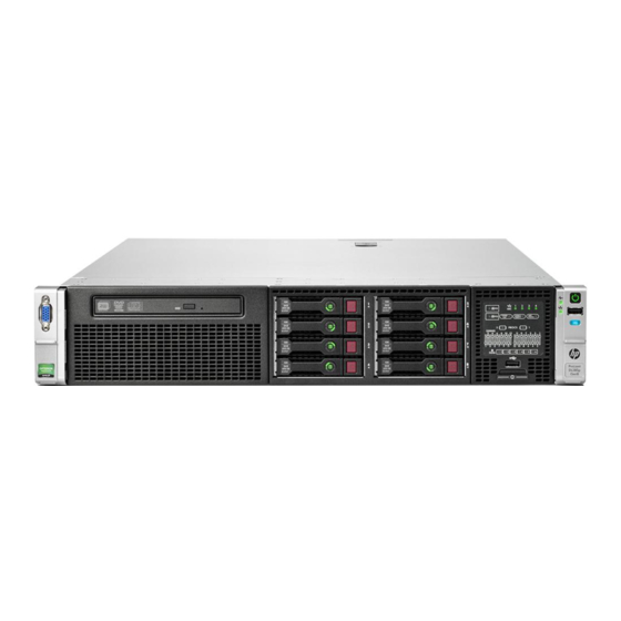
Page 7: Component Identification
Component identification Front panel components • 8 drive SFF configuration Item Description Video connector Quick release levers (2) SATA optical drive bay SFF drive bays Serial number label USB connectors (2) Systems Insight Display • 16 drive SFF configuration (with optional drive cage) Item Description Video connector... - Page 8 Item Description Drive bays (box 1) Drive bays (box 2) Systems Insight Display USB connectors (2) • 25 SFF drive configuration Item Description Video connector Quick release levers (2) Drive bays USB connector • 8 drive LFF configuration Item Description Video connector Quick release levers (2) Drive bays...
-
Page 9: Front Panel Leds And Buttons
• 12 drive LFF configuration Item Description Video connector Quick release levers (2) Drive bays USB connector Front panel LEDs and buttons • Component identification 9... -
Page 10: Access The Systems Insight Display
**Facility power is not present, power cord is not attached, no power supplies are installed, power supply failure has occurred, or the power button cable is disconnected. Access the Systems Insight Display To access the HP Systems Insight Display in a server with an 8-drive LFF configuration: Press and release the panel. Component identification 10... -
Page 11: Systems Insight Display Leds
After the display fully ejects, rotate the display downward to view the LEDs. Systems Insight Display LEDs The HP Systems Insight Display LEDs represent the system board layout. The display, available on 8 SFF, 16 SFF, and 8 LFF configurations, enables diagnosis with the access panel installed. -
Page 12: Systems Insight Display Led Combinations
Item Description Status NIC link/activity Off = No link to network. If the power is off, view the rear panel RJ-45 LEDs for status. Flashing green = Network link and activity Solid green = Network link AMP status Off = AMP modes disabled Solid green = AMP mode enabled Solid amber = Failover Flashing amber = Invalid configuration... -
Page 13: Rear Panel Components
Systems Insight Display Health LED System power Status LED and color • Power supply fault • System board fault Amber Green One or more of the following conditions may Power supply (amber) exist: • Redundant power supply is installed and only one power supply is functional. -
Page 14: Rear Panel Leds And Buttons
Rear panel LEDs and buttons Item Description Status UID LED/button Off = Deactivated Solid blue = Activated Flashing blue = System being managed remotely Power supply 2 Off = System is off or power supply has failed. Solid green = Normal Power supply 1 Off = System is off or power supply has failed. -
Page 15: System Board Components
• The riser cages support a maximum power of 150 W with an HP power cable. This cable must be used for PCIe card wattages greater than 75 W. System board components Item Description Fan connector 6 Systems Insight Display connector... -
Page 16: System Maintenance Switch
SAS port 2i SAS cache module connector System maintenance switch Position Default Function Off = HP iLO security is enabled. On = HP iLO security is disabled. Off = System configuration can be changed. On = System configuration is locked. Reserved Reserved Off = Power-on password is enabled. -
Page 17: Nmi Functionality
To force the OS to invoke the NMI handler and generate a crash dump log, the administrator can use the iLO Virtual NMI feature. For more information, see the white paper on the HP website (http://h20000.www2.hp.com/bc/docs/support/SupportManual/c00797875/c00797875.pdf). DIMM slot locations DIMM slots are numbered sequentially (1 through 12) for each processor. -
Page 18: Sas And Sata Device Numbers
SAS and SATA device numbers • 8 SFF device bay numbering • 16 SFF device bay numbering • 25 SFF device bay numbering • 8 LFF device bay numbering Component identification 18... -
Page 19: Drive Led Definitions
• 12 LFF device bay numbering Drive LED definitions Item Status Definition Locate Solid blue The drive is being identified by a host application. Flashing blue The drive carrier firmware is being updated or requires an update. Activity ring Rotating green Drive activity No drive activity Do not remove... -
Page 20: Fbwc Module Leds (P222, P420, P421)
Status On = AC power is connected. Off = AC power is disconnected. Missing = Riser cage is not installed, or power might not be connected. FBWC module LEDs (P222, P420, P421) The FBWC module has three single-color LEDs (one amber and two green). The LEDs are duplicated on the reverse side of the cache module to facilitate status viewing. -
Page 21: Hot-Plug Fans
1 - Amber 2 - Green 3 - Green Interpretation The cache module is not powered. Flashing 0.5 Hz Flashing 0.5 Hz The cache microcontroller is executing from within its boot loader and receiving new flash code from the host controller. - Page 22 • At POST and in the OS, HP iLO performs an orderly shutdown if a cautionary temperature level is detected. If the server hardware detects a critical temperature level before an orderly shutdown occurs, the server performs an immediate shutdown.
-
Page 23: Operations
If an application stops responding, you can use this method to force a shutdown. • Use a virtual power button selection through HP iLO. This method initiates a controlled remote shutdown of applications and the OS before the server enters standby mode. -
Page 24: Remove The Server From The Rack
The sliding rails could pinch your fingers. Remove the server from the rack To remove the server from an HP, Compaq branded, telco, or third-party rack: Power down the server (on page 23). -
Page 25: Remove The Access Panel
Remove the access panel WARNING: To reduce the risk of personal injury from hot surfaces, allow the drives and the internal system components to cool before touching them. CAUTION: For proper cooling, do not operate the server without the access panel, baffles, expansion slot covers, or blanks installed. -
Page 26: Remove The Fan Cage
Open the cable management arm. Note that the cable management arm can be right-mounted or left-mounted. Remove the fan cage To remove the component: Power down the server (on page 23). Remove all power: Disconnect each power cord from the power source. Disconnect each power cord from the server. -
Page 27: Remove The Hot-Plug Fan
Remove the fan cage. CAUTION: Do not operate the server for long periods with the access panel open or removed. Operating the server in this manner results in improper airflow and improper cooling that can lead to thermal damage. IMPORTANT: For optimum cooling, install fans in all primary fan locations. -
Page 28: Remove The Full-Length Expansion Board
Remove the fan. CAUTION: Do not operate the server for long periods with the access panel open or removed. Operating the server in this manner results in improper airflow and improper cooling that can lead to thermal damage. IMPORTANT: For optimum cooling, install fans in all primary fan locations. For more information, refer to the fan locations table ("Hot-plug fans"... -
Page 29: Remove The Primary Pcie Riser Cage
If a full-length expansion board is installed in slot 1, release the full-length expansion board retainer, and then remove the primary PCIe riser cage. If a full-length expansion board is installed in slot 4, release the full-length expansion board retainer, and then remove the secondary PCIe riser cage. -
Page 30: Remove The Secondary Pcie Riser Cage
Disconnect each power cord from the power source. Disconnect each power cord from the server. Extend the server from the rack (on page 23). Remove the access panel (on page 25). Remove any installed full-length expansion boards. Remove the PCIe riser cage. To install the component, reverse the removal procedure. -
Page 31: Install The Primary Pcie Riser Cage
If a full-length expansion board is installed in slot 4, release the full-length expansion board retainer, and then remove the PCIe riser cage. To install the component, reverse the removal procedure. Install the primary PCIe riser cage WARNING: To reduce the risk of personal injury, electric shock, or damage to the equipment, remove the power cord to remove power from the server. -
Page 32: Secure The Primary Pcie Riser Cage Full-Length Expansion Board Retainer
Install the PCIe riser cage. Install the access panel (on page 25). Install the server into the rack ("Installing the server into the rack" on page 40). Connect each power cord to the server. Connect each power cord to the power source. Power up the server (on page 23). -
Page 33: Secure The Secondary Pcie Riser Cage Full-Length Expansion Board Retainer
Secure the full-length expansion board retainer. Install the access panel (on page 25). Install the server into the rack ("Installing the server into the rack" on page 40). Connect each power cord to the server. Connect each power cord to the power source. Power up the server (on page 23). -
Page 34: Remove The Air Baffle
Secure the full-length expansion board retainer. Install the access panel (on page 25). Install the server into the rack ("Installing the server into the rack" on page 40). Connect each power cord to the server. Connect each power cord to the power source. Power up the server (on page 23). - Page 35 If a full-length expansion board is installed in the secondary PCIe riser cage, release the expansion board retainer and remove the secondary PCIe riser cage (on page 30). Remove the air baffle. To install the component, reverse the removal procedure. Operations 35...
-
Page 36: Setup
For more information on HP Care Pack Services, see the HP website (http://www.hp.com/services/carepack). Rack planning resources The rack resource kit ships with all HP branded or Compaq branded 9000, 10000, and H9 series racks. For more information on the content of each resource, see the rack resource kit documentation. Optimum environment When installing the server in a rack, select a location that meets the environmental standards described in this section. -
Page 37: Space And Airflow Requirements
HP servers draw in cool air through the front door and expel warm air through the rear door. Therefore, the front and rear rack doors must be adequately ventilated to allow ambient room air to enter the cabinet, and the rear door must be adequately ventilated to allow the warm air to escape from the cabinet. -
Page 38: Power Requirements
Because of the high ground-leakage currents associated with multiple servers connected to the same power source, HP recommends the use of a PDU that is either permanently wired to the building’s branch circuit or includes a nondetachable cord that is wired to an industrial-style plug. NEMA locking-style plugs or those complying with IEC 60309 are considered suitable for this purpose. -
Page 39: Rack Warnings
Stack each same-colored pair of wires and then attach them to the same power source. The power cord consists of three wires (black, red, and green). For more information, see the HP 750W Common Slot -48V DC Input Hot-Plug Power Supply Installation Instructions. -
Page 40: Identifying The Contents Of The Server Shipping Carton
WARNING: To reduce the risk of personal injury or damage to the equipment, be sure that: • The leveling jacks are extended to the floor. The full weight of the rack rests on the leveling jacks. • The stabilizing feet are attached to the rack if it is a single-rack installation. •... - Page 41 WARNING: To reduce the risk of electric shock, fire, or damage to the equipment, do not plug telephone or telecommunications connectors into RJ-45 connectors. Connect the power cord to the rear of the server. Install the power cord anchors. Secure the cables to the cable management arm. IMPORTANT: When using cable management arm components, be sure to leave enough slack in each of the cables to prevent damage to the cables when the server is extended from the rack.
-
Page 42: Installing The Operating System
Installing the operating system This HP ProLiant server does not ship with provisioning media. Everything needed to manage and install the system software and firmware is preloaded on the server. To operate properly, the server must have a supported operating system. For the latest information on operating system support, see the HP website (http://www.hp.com/go/supportos). -
Page 43: Registering The Server
F10 to access Intelligent Provisioning. NOTE: If an HP Smart Array controller has been added or is embedded in the system, the controller defaults to a RAID configuration based on the size and number of hard drives installed. For more information on modifying the controller default settings, see the documentation on the Documentation CD. -
Page 44: Hardware Options Installation
To install the component: Update the system ROM. Locate and download the latest ROM version from the HP website (http://www.hp.com/support). Follow the instructions on the website to update the system ROM. Power down the server (on page 23). Remove all power: Disconnect each power cord from the power source. - Page 45 If a full-length expansion board is installed in the primary PCIe riser cage, release the full-length expansion board retainer, and then remove the PCIe riser cage. If a full-length expansion board is installed in the secondary PCIe riser cage, release the full-length expansion board retainer, and then remove the PCIe riser cage.
- Page 46 Remove the air baffle (on page 34). Open the heatsink retaining bracket, and then remove the heatsink blank. Hardware options installation 46...
- Page 47 Open the processor socket locking lever and the retaining bracket, and then remove the processor socket protective cover. IMPORTANT: Be sure the processor remains inside the processor installation tool. If the processor has separated from the installation tool, carefully re-insert the processor in the tool. Handle the processor by the edges only, and do not touch the bottom of the processor, especially the contact area.
- Page 48 The processor fits one way into the socket. Use the alignment guides on the processor and socket to properly align the processor with the socket. Install the spare processor. THE PINS ON THE SYSTEM BOARD ARE VERY FRAGILE AND EASILY DAMAGED. CAUTION: THE PINS ON THE SYSTEM BOARD ARE VERY FRAGILE AND EASILY DAMAGED.
- Page 49 Remove the heatsink cover. CAUTION: After the cover is removed, do not touch the thermal interface media. Install the heatsink, and close the heatsink retaining bracket. Be sure to align the pins on the heatsink with the pins on the processor cage. Hardware options installation 49...
- Page 50 Remove the fan blanks from bays 1 and 2. Install the fans into bays 1 and 2. Hardware options installation 50...
- Page 51 Install the air baffle. Install the primary PCIe riser cage. Hardware options installation 51...
-
Page 52: Memory Options
Install the secondary PCIe riser cage. If necessary, secure the full-length expansion board retainer for the primary or the secondary PCIe riser cages on the air baffle. Install the access panel (on page 25). Install the server into the rack. Connect each power cord to the server. - Page 53 The memory subsystem in this server can support LRDIMMs or RDIMMs: • RDIMMs offer lower latency in one DIMM per channel configurations and (relatively) low power consumption. They include address parity protection. • LRDIMMs support higher densities than single- and dual-rank RDIMMs, and higher speeds than quad-rank RDIMMs.
-
Page 54: Hp Smartmemory
Not allowed. System halts during POST. Not allowed. System halts during POST. HP SmartMemory HP SmartMemory, introduced for Gen8 servers, authenticates HP Qualified memory and verifies whether installed memory has passed HP qualification and test processes. Hardware options installation 54... -
Page 55: Memory Subsystem Architecture
Memory subsystem architecture The memory subsystem in this server is divided into channels. Each processor supports four channels, and each channel supports three DIMM slots, as illustrated. This multi-channel architecture provides enhanced performance in Advanced ECC mode. This architecture also enables Online Spare Memory modes. DIMM slots in this server are identified by number and by letter: •... -
Page 56: Dimm Identification
E = UDIMM (unbuffered with ECC) L = LRDIMM (load reduced) For the latest supported memory information, see the QuickSpecs on the HP website (http://h18000.www1.hp.com/products/quickspecs/ProductBulletin.html). At the website, choose the geographic region, and then locate the product by name or product category. -
Page 57: Memory Configurations
Advanced ECC provides additional protection over Standard ECC because it is possible to correct certain memory errors that would otherwise be uncorrected and result in a server failure. Using HP Advanced Memory Error Detection technology, the server provides notification when a DIMM is degrading and has a higher probability of uncorrectable memory error. -
Page 58: Installing A Dimm
P1-A, P2-A, P1-B, P2-B, P1-C, P2-C, and so on. For detailed memory configuration rules and guidelines, use the Online DDR3 Memory Configuration Tool on the HP website (http://www.hp.com/go/ddr3memory-configurator). Advanced ECC population guidelines For Advanced ECC mode configurations, observe the following guidelines: •... -
Page 59: Hot-Plug Hard Drive Options
Connect each power cord to the power source. Power up the server (on page 23). Use RBSU ("HP ROM-Based Setup Utility" on page 103) to configure the memory mode. For more information about LEDs and troubleshooting failed DIMMs, see "Systems Insight Display LED combinations (on page 12)."... -
Page 60: Removing A Hot-Plug Sas Or Sata Hard Drive
Remove the drive blank. Prepare the drive. Install the drive. Determine the status of the drive from the drive LED definitions (on page 19). Removing a hot-plug SAS or SATA hard drive CAUTION: For proper cooling, do not operate the server without the access panel, baffles, expansion slot covers, or blanks installed. -
Page 61: Controller Options
The server ships with an embedded Smart Array P420i controller. For more information about the controller and its features, see the HP Smart Array Controllers for HP ProLiant Servers User Guide on the HP website (http://www.hp.com/support/SAC_UG_ProLiantServers_en). To configure arrays, see the Configuring Arrays on HP Smart Array Controllers Reference Guide on the HP website (http://www.hp.com/support/CASAC_RG_en). -
Page 62: Installing The Flash-Backed Write Cache Module
NOTE: The data protection and the time limit also apply if a power outage occurs. When power is restored to the system, an initialization process writes the preserved data to the hard drives. Installing the flash-backed write cache module CAUTION: The cache module connector does not use the industry-standard DDR3 mini-DIMM pinout. -
Page 63: Installing The Fbwc Capacitor Pack
Connect the capacitor pack cable to the connector on the top of the cache module. Install the access panel (on page 25). Install the server into the rack ("Installing the server into the rack" on page 40). Connect each power cord to the server. Connect each power cord to the power source. - Page 64 Connect the capacitor pack cable to the connector on the top of the cache module. Install one or two FBWC capacitor packs into the FBWC capacitor pack holder. Install the FBWC capacitor pack holder into the server: Hardware options installation 64...
- Page 65 8 or 16 drive SFF 8 drive LFF Hardware options installation 65...
-
Page 66: Optical Drive Option
• 12 drive LFF • 25 drive SFF Install the access panel (on page 25). Install the server into the rack ("Installing the server into the rack" on page 40). Connect each power cord to the server. Connect each power cord to the power source. Power up the server (on page 23). - Page 67 Disconnect each power cord from the server. Extend the server from the rack (on page 23). Remove the access panel (on page 25). Remove the existing media drive option or blank. Slide the optical drive into the drive bay. Hardware options installation 67...
-
Page 68: Redundant Hot-Plug Power Supply Option
Advisor to determine the right size power supply for your server configuration. HP Power Advisor is available as both an online tool, running directly from the HP website, and as a downloadable tool. Instructions on how to download and use the tool are available on the HP website (http://www.hp.com/go/hppoweradvisor). -
Page 69: Flexiblelom Option
Connect the power cord to the power supply. Route the power cord. Use best practices when routing power cords and other cables. A cable management arm is available to help with routing. To obtain a cable management arm, contact an HP authorized reseller. - Page 70 To remove the component: Power down the server (on page 23). Remove all power: Disconnect each power cord from the power source. Disconnect each power cord from the server. Remove any attached network cables. Extend the server from the rack (on page 23). Remove the access panel (on page 25).
-
Page 71: Expansion Board Options
To install the component: Firmly seat the optional FlexibleLOM in the slot, and then tighten the thumbscrew. Install the primary PCIe riser cage (on page 31). Install the access panel (on page 25). Slide the server into the rack. Connect the LAN segment cables. Connect each power cord to the server. -
Page 72: Installing A Half-Length Expansion Board
Extend the server from the rack (on page 23). Remove the access panel (on page 25). If you need to remove a blank from the primary PCIe riser cage, remove the PCIe riser cage ("Remove the primary PCIe riser cage" on page 29). If you need to remove a blank from the secondary PCIe riser cage, remove the secondary PCIe riser cage (on page 30). -
Page 73: Installing A Full-Length Expansion Board
Install the expansion board. Connect any required internal or external cables to the expansion board. See the documentation that ships with the expansion board. Do one of the following: Install the primary PCIe riser cage (on page 31). Install the secondary PCIe riser cage ("Secondary PCIe riser cage option"... -
Page 74: Secondary Pcie Riser Cage Option
Install the primary PCIe riser cage (on page 31). Install the secondary PCIe riser cage ("Secondary PCIe riser cage option" on page 74). Do one of the following: Secure the primary PCIe riser cage full-length expansion board retainer (on page 32). Secure the secondary PCIe riser cage full-length expansion board retainer (on page 33). - Page 75 Remove the PCI riser blank. Remove the blank from the optional secondary PCI riser cage. Hardware options installation 75...
-
Page 76: Hard Drive Cage Option
Install an expansion board into the PCI riser cage, if needed. Connect any internal or external cables. Install the optional secondary PCIe riser cage. If not already installed, install the secondary processor ("Processor option" on page 44). Install the access panel (on page 25). Install the server into the rack ("Installing the server into the rack"... - Page 77 To install the component: Power down the server (on page 23). Remove all power: Disconnect each power cord from the power source. Disconnect each power cord from the server. Extend the server from the rack (on page 23). Remove the access panel (on page 25). If a full-length expansion board is installed in slot 1, release the full-length expansion board retainer, and then remove the primary PCIe riser cage.
- Page 78 Remove the fan cage. Disconnect and remove the optical drive cable, if installed: Disconnect the cable. Hardware options installation 78...
- Page 79 Remove the cable from the DIMM guard. Using a T-15 Torx screwdriver, remove the two optical drive retaining screws, and then remove the optical drive cage. Hardware options installation 79...
- Page 80 Install the optional hard drive cage. Install the hard drives or hard drive blanks. To access the cables, remove the fan bracket on the right side of the chassis. Connect the cables: Hardware options installation 80...
- Page 81 Connect one end of the power cable to the SAS backplane and the other end to the power connector on the system board. Remove the existing SAS cable from the cable guide and from the system board. Hardware options installation 81...
- Page 82 Connect the end of each SAS signal cable to the SAS backplane, and then route the SAS signal cables behind the cable guide. Do not connect the other ends yet. Install the fan bracket. Be sure that the cables are properly routed in the channel along the fan bracket. Hardware options installation 82...
- Page 83 Install the fan cage. Install the air baffle. If you do not have a full-length expansion board, the air baffle can be installed last. Hardware options installation 83...
- Page 84 Remove the blank from the PCIe riser cage. Install the SAS controller board into the PCIe riser cage. Connect the other end of the SAS signal cables to the SAS controller board and to the system board. Then, install the PCe riser cage. Hardware options installation 84...
- Page 85 SAS cables can be connected to the PCIe riser cage and the system board before or after the PCIe riser cage is installed. For ease in accessing connectors, HP recommends connecting the cables before the PCIe riser cage is installed.
-
Page 86: 2U Rack Bezel Option
HP Trusted Platform Module option For more information about product features, specifications, options, configurations, and compatibility, see the product QuickSpecs on the HP Product Bulletin website (http://www.hp.com/go/productbulletin). Use these instructions to install and enable a TPM on a supported server. This procedure includes three sections: Installing the Trusted Platform Module board. -
Page 87: Installing The Trusted Platform Module Board
Recovery Mode after BitLocker detects a possible compromise of system integrity. • HP is not liable for blocked data access caused by improper TPM use. For operating instructions, see the encryption technology feature documentation provided by the operating system. - Page 88 Install the TPM board. Press down on the connector to seat the board ("System board components" on page 15). Install the TPM security rivet by pressing the rivet firmly into the system board. Install the air baffle. Do the following: Install the primary PCIe riser cage (on page 31).
-
Page 89: Retaining The Recovery Key/Password
OS application TPM settings. For more information on firmware updates and hardware procedures, see the HP Trusted Platform Module Best Practices White Paper on the HP website (http://www.hp.com/support). -
Page 90: Cabling
Cabling SAS hard drive cabling • SFF hard drive cabling • SFF cabling, with optional drive cage Cabling 90... -
Page 91: Optical Drive Cabling
• LFF hard drive cabling Optical drive cabling Cabling 91... -
Page 92: Fbwc Cabling
FBWC cabling • 8 or 16 drive SFF • 8 drive LFF Cabling 92... -
Page 93: Chipset Sata Cable Option
• 12 LFF or 25 SFF • PCIe option Depending on the server configuration, you may need to remove the primary PCIe riser cage (on page 29) before cabling to a PCIe expansion board. Chipset SATA cable option With the chipset SATA cable option, the chipset SATA controller can be used with a single SATA hard drive that is installed in one hard drive bay of the SFF or LFF hard drive cage. - Page 94 For proper thermal cooling, install blanks in all bays that do not have a drive installed. Order a sufficient number of 6.35-cm (2.5-in) or 8.89-cm (3.5-in) hard drive blank option kits from an HP authorized reseller. For more information, see the server maintenance and service guide.
- Page 95 If a full-length expansion board is installed in slot 4, release the full-length expansion board retainer, and then remove the secondary PCIe riser cage. Remove the air baffle (on page 34). Remove the fan cage (on page 26). Disconnect any SAS cables from the hard drive cage and either the embedded SAS controller or an optional SAS controller.
- Page 96 Disconnect the SATA cable from the optical drive and the SATA connector on the system board. The optical bay is disabled with the chipset SATA cable option. Connect the chipset SATA cable: Connect the chipset SATA cable connector to the chipset SATA controller port on the system board. The chipset SATA connector on the SATA cable is narrower than the chipset SATA controller port header on the system board.
-
Page 97: 150W Pcie Power Cable Option
Connect each power cord to the power source. Power up the server (on page 23). Use RBSU ("HP ROM-Based Setup Utility" on page 103) to disable the embedded HP Smart Array P420i Controller, if necessary. 150W PCIe power cable option CAUTION: To prevent damage to the server or expansion boards, power down the server and remove all AC power cords before removing or installing the PCI expansion cage. -
Page 98: Software And Configuration Utilities
HP iLO The HP iLO subsystem is a standard component of selected HP ProLiant servers that simplifies initial server setup, server health monitoring, power and thermal optimization, and remote server administration. The HP iLO subsystem includes an intelligent microprocessor, secure memory, and a dedicated network interface. -
Page 99: Active Health System
HP Active Health System does not parse or change operating system data from third-party error event log activities, such as content created or passed through by the operating system. The data that is collected is managed according to the HP Data Privacy policy. For more information see the HP website (http://www.hp.com/go/privacy). -
Page 100: Intelligent Provisioning
HP website (http://www.hp.com/go/spp/download). The Active Health System log can be downloaded manually from HP iLO or HP Intelligent Provisioning and sent to HP. For more information, see the HP iLO User Guide or HP Intelligent Provisioning User Guide on the HP website (http://www.hp.com/go/ilo/docs). -
Page 101: Hp Insight Diagnostics
For more information or to download the utility, see the HP website (http://www.hp.com/servers/diags). HP Insight Diagnostics Online Edition is also available in the SPP. For more information, see the HP website (http://www.hp.com/go/spp/download). -
Page 102: Hp Insight Remote Support Software
HP strongly recommends that you install HP Insight Remote Support software to complete the installation or upgrade of your product and to enable enhanced delivery of your HP Warranty, HP Care Pack Service, or HP contractual support agreement. HP Insight Remote Support supplements your monitoring continuously to... -
Page 103: Hp Smart Update Manager
SPP has several key features for updating HP ProLiant servers. Using HP SUM as the deployment tool, SPP can be used in an online mode on a Windows or Linux hosted operating system, or in an offline mode where the server is booted to the ISO so that the server can be updated automatically with no user interaction or updated in interactive mode. -
Page 104: Using Rbsu
For more information on RBSU, see the HP ROM-Based Setup Utility User Guide on the Documentation CD or the HP website (http://www.hp.com/support/rbsu). Using RBSU To use RBSU, use the following keys: • To access RBSU, press the F9 key during power-up when prompted. -
Page 105: Boot Options
Force a PXE Network boot by pressing the F12 key. Configuring AMP modes Not all HP ProLiant servers support all AMP modes. RBSU provides menu options only for the modes supported by the server. Advanced memory protection within RBSU enables the following advanced memory modes: •... -
Page 106: Utilities And Features
Provides context-sensitive searchable help content • Provides diagnostic and SmartSSD Wear Gauge functionality on the Diagnostics tab ACU is now available as an embedded utility, starting with HP ProLiant Gen8 servers. To access ACU, use one of the following methods: •... -
Page 107: Option Rom Configuration For Arrays
ASR is a feature that causes the system to restart when a catastrophic operating system error occurs, such as a blue screen, ABEND (does not apply to HP ProLiant DL980 Servers), or panic. A system fail-safe timer, the ASR timer, starts when the System Management driver, also known as the Health Driver, is loaded. When the operating system is functioning properly, the system periodically resets the timer. -
Page 108: Redundant Rom Support
To locate the drivers for a particular server, go to the HP website (http://www.hp.com/go/hpsc) and click on Drivers, Software & Firmware. Then, enter your product name in the Find an HP product field and click Software and configuration utilities 108... -
Page 109: Software And Firmware
Administrators configure VCA to point to a repository managed by VCRM. For more information about version control tools, see the HP Systems Insight Manager User Guide, the HP Version Control Agent User Guide, and the HP Version Control Repository User Guide on the HP website (http://www.hp.com/go/hpsim). -
Page 110: Hp Technology Service Portfolio
If the problem is identified as hardware, HP will resolve as per service level commitments. If the reported incident is related to HP or supported 3rd party software product and cannot be resolved by applying known fixes, HP will contact the third-party vendor and create a problem incident on the your behalf. -
Page 111: Troubleshooting
• Simplified Chinese (http://www.hp.com/support/ProLiant_TSG_v1_sc) The HP ProLiant Gen8 Troubleshooting Guide, Volume II: Error Messages provides a list of error messages and information to assist with interpreting and resolving error messages on ProLiant servers and server blades. To view the guide, select a language: •... -
Page 112: Battery Replacement
Battery replacement If the server no longer automatically displays the correct date and time, you may need to replace the battery that provides power to the real-time clock. WARNING: The computer contains an internal lithium manganese dioxide, a vanadium pentoxide, or an alkaline battery pack. A risk of fire and burns exists if the battery pack is not properly handled. - Page 113 For more information about battery replacement or proper disposal, contact an authorized reseller or an authorized service provider. Battery replacement 113...
-
Page 114: Regulatory Information
Regulatory information Safety and regulatory compliance For safety, environmental, and regulatory information, see Safety and Compliance Information for Server, Storage, Power, Networking, and Rack Products, available at the HP website (http://www.hp.com/support/Safety-Compliance-EnterpriseProducts). Turkey RoHS material content declaration Ukraine RoHS material content declaration Warranty information HP ProLiant and X86 Servers and Options (http://www.hp.com/support/ProLiantServers-Warranties) -
Page 115: Electrostatic Discharge
Electrostatic discharge Preventing electrostatic discharge To prevent damaging the system, be aware of the precautions you need to follow when setting up the system or handling parts. A discharge of static electricity from a finger or other conductor may damage system boards or other static-sensitive devices. -
Page 116: Specifications
21.15 kg−28.37 kg (46.6 lb−62.5 Weight, 25 SFF Power supply specifications Depending on installed options, the server is configured with one of the following power supplies: • HP 460 W CS Gold power supply (92% efficiency) (on page 117) Specifications 116... -
Page 117: Hp 460 W Cs Gold Power Supply (92% Efficiency)
• HP 460 W CS Platinum Plus power supply (94% efficiency) (on page 117) • HP 750 W CS Gold power supply (92% efficiency) (on page 118) • HP 750 W CS Platinum Plus power supply (94% efficiency) (on page 118) •... -
Page 118: Hp 750 W Cs Gold Power Supply (92% Efficiency)
750 W at 100 V to 120 V AC Maximum peak power input 750 W at 200 V to 240 V AC input HP 750 W CS Platinum Plus power supply (94% efficiency) Specification Value Input requirements — 100V to 240V AC... -
Page 119: Hp 750 W 48V Cs Dc Power Supply (94% Efficiency)
HP 750 W 48V CS DC power supply (94% efficiency) Specification Value Input requirements — -36V to -72V DC Rated input voltage -48V DC, nominal input Rated input frequency 2.3A at -36V DC Rated input current 12A at -72V DC... - Page 120 50 Hz to 60 Hz Rated input frequency 9.1A to 5.5A Rated input current 897 W at 100V AC input Maximum rated input power 1321 W at 200V AC input 3061 at 100V AC input Btus per hour 4506 at 200V AC input Power supply output —...
-
Page 121: Support And Other Resources
Active Health System log (HP ProLiant Gen8 or later products) Download and have available an Active Health System log for 3 days before the failure was detected. For more information, see the HP iLO 4 User Guide or HP Intelligent Provisioning User Guide on the HP website (http://www.hp.com/go/ilo/docs). - Page 122 HP specifies in the materials shipped with a replacement CSR part whether a defective part must be returned to HP. In cases where it is required to return the defective part to HP, you must ship the defective part back to HP within a defined period of time, normally five (5) business days. The defective part must be returned with the associated documentation in the provided shipping material.
- Page 123 HP sono realizzati con numerosi componenti che possono essere riparati direttamente dal cliente (CSR, Customer Self Repair). Se in fase di diagnostica HP (o un centro di servizi o di assistenza HP) identifica il guasto come riparabile mediante un ricambio CSR, HP lo spedirà direttamente al cliente per la sostituzione.
- Page 124 Si, durante la fase de diagnóstico, HP (o los proveedores o socios de servicio de HP) identifica que una reparación puede llevarse a cabo mediante el uso de un componente CSR, HP le enviará dicho componente directamente para que realice su sustitución. Los componentes CSR se clasifican en dos categorías:...
- Page 125 HP se hará cargo de todos los gastos de envío y devolución de componentes y escogerá la empresa de transporte que se utilice para dicho servicio. Para obtener más información acerca del programa de Reparaciones del propio cliente de HP, póngase en contacto con su proveedor de servicios local.
- Page 126 Opcional – Peças cujo reparo feito pelo cliente é opcional. Essas peças também são projetadas para o reparo feito pelo cliente. No entanto, se desejar que a HP as substitua, pode haver ou não a cobrança de taxa adicional, dependendo do tipo de serviço de garantia destinado ao produto.
- Page 127 Support and other resources 127...
- Page 128 Support and other resources 128...
-
Page 129: Acronyms And Abbreviations
Acronyms and abbreviations ABEND abnormal end Array Configuration Utility Advanced Memory Protection Automatic Server Recovery Canadian Standards Association Customer Self Repair double data rate FBWC flash-backed write cache International Electrotechnical Commission Integrated Lights-Out Integrated Management Log large form factor Acronyms and abbreviations 129... - Page 130 nonmaskable interrupt NVRAM nonvolatile memory ORCA Option ROM Configuration for Arrays PCIe peripheral component interconnect express POST Power-On Self Test RBSU ROM-Based Setup Utility RDIMM registered dual in-line memory module Rapid Deployment Pack serial attached SCSI SATA serial ATA SELV separated extra low voltage small form factor Systems Insight Manager...
- Page 131 Trusted Platform Module unit identification universal serial bus Version Control Agent Acronyms and abbreviations 131...
-
Page 132: Documentation Feedback
Documentation feedback HP is committed to providing documentation that meets your needs. To help us improve the documentation, send any errors, suggestions, or comments to Documentation Feedback (mailto:docsfeedback@hp.com). Include the document title and part number, version number, or the URL when submitting your feedback. - Page 133 7 Federal Communications Commission (FCC) configuration of system 42, 98 notice 114 connectors 7 firmware 109 contacting HP 121 front panel buttons 9 controller 61 front panel components 7 crash dump analysis 17 CSR (customer self repair) 121...
- Page 134 SAS hard drive options 59 operating system crash 17 HP Insight Diagnostics 101 operating systems 42, 109 HP Insight Remote Support software 102, 110 optical drive 7, 66 HP Smart Update Manager overview 98, 103 optical drive cable 91...
- Page 135 39, 108, 114 SAS and SATA device numbers 18 scripted installation 102 warnings 39 serial number 105 website, HP 121 series number 114 server features and options 44 server setup 108 shipping carton contents 40 space and airflow requirements 37...