Dell PowerEdge R320 Owner's Manual
Hide thumbs
Also See for PowerEdge R320:
- Planning, installation and service manual (67 pages) ,
- Technical manual (51 pages) ,
- Getting started manual (11 pages)

Related Manuals for Dell PowerEdge R320


Summary of Contents for Dell PowerEdge R320
- Page 1 Dell PowerEdge R320 Systems Owner's Manual Regulatory Model: E18S Series Regulatory Type: E18S001...
- Page 2 CAUTION: A CAUTION indicates either potential damage to hardware or loss of data and tells you how to avoid the problem. WARNING: A WARNING indicates a potential for property damage, personal injury, or death. © 2013 Dell Inc. All Rights Reserved. Trademarks used in this text: Dell , the Dell logo, Dell Boomi...
-
Page 3: Table Of Contents
Contents 1 About Your System........................9 ........................9 Front-Panel Features And Indicators ..............................12 LCD Panel Features ..............................13 Home Screen ..............................13 Setup Menu ............................... 14 View Menu ..............................14 Diagnostic Indicators ..........................16 Hard-Drive Indicator Patterns ........................17 Back-Panel Features And Indicators ..............................18 NIC Indicator Codes ............................ - Page 4 ............................34 Boot Manager Screen ............................... 34 UEFI Boot Menu ..........................34 Embedded System Management ..............................34 iDRAC Settings Utility ........................35 Entering The iDRAC Settings Utility ........................35 Changing The Thermal Settings 3 Installing System Components....................37 .............................. 37 Recommended Tools ............................. 37 Front Bezel (Optional) ..........................37 Installing The Front Bezel ..........................38...
- Page 5 ................61 Installing The Optical Drive In Cabled Hard-Drive Systems ................................62 Cooling Fans ...........................62 Removing A Cooling Fan ............................63 Installing A Cooling Fan ........................64 Internal USB Memory Key (Optional) ........................64 Replacing The Internal USB Key ......................64 Expansion Cards And Expansion-Card Risers ......................65 Expansion Card Installation Guidelines ..........................
- Page 6 ............................89 Control Panel Assembly ..........................90 Removing The Control Panel ..........................91 Installing The Control Panel ......................92 Removing The Control-Panel Module ....................... 95 Installing The Control-Panel Module ................................96 VGA Module ..........................96 Removing The VGA Module ..........................97 Installing The VGA Module ...........................97 Power Distribution Board Shroud ....................
- Page 7 5 Using System Diagnostics..................... 113 ............................113 Dell Online Diagnostics ........................113 Dell Embedded System Diagnostics ..................113 When To Use The Embedded System Diagnostics ....................113 Running The Embedded System Diagnostics ........................... 114 System Diagnostic Controls 6 Jumpers And Connectors...................... 115 ..........................
-
Page 9: About Your System
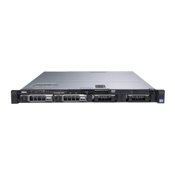
About Your System Front-Panel Features And Indicators Figure 1. Front-Panel Features and Indicators—Four 3.5 Inch Hard-Drive System Item Indicator, Button, or Icon Description Connector Power-on indicator, power The power-on indicator lights when the system power is button on. The power button controls the power supply output to the system. - Page 10 Item Indicator, Button, or Icon Description Connector LCD panel Displays system ID, status information, and system error messages. The LCD lights blue during normal system operation. The LCD lights amber when the system needs attention, and the LCD panel displays an error code followed by descriptive text.
- Page 11 Item Indicator, Button, or Icon Description Connector When one of these buttons is pressed, the LCD panel on the front and the system status indicator on the back flashes until one of the buttons is pressed again. Press to toggle the system ID on and off. If the system stops responding during POST, press and hold the system ID button for more than five seconds to enter BIOS progress mode.
-
Page 12: Lcd Panel Features
Item Indicator, Button, or Icon Description Connector NOTE: On ACPI-compliant operating systems, turning off the system using the power button causes the system to perform a graceful shutdown before power to the system is turned off. Used to troubleshoot software and device driver errors NMI button when running certain operating systems. -
Page 13: Home Screen
Figure 4. LCD Panel Features Item Button Description Left Moves the cursor back in one-step increments. Select Selects the menu item highlighted by the cursor. Right Moves the cursor forward in one-step increments. During message scrolling: • Press once to increase scrolling speed •... -
Page 14: View Menu
Option Description Select Simple to display LCD error messages in a simplified user-friendly description. See System Error Messages for a list of messages in this format. Set home Select the default information to be displayed on the LCD Home screen. See View Menu to see the options and option items that can be set as the default on the Home screen. - Page 15 Hard-drive indicator Condition Corrective Action The indicator lights None required. green to indicate hard-drive activity.. Electrical indicator Condition Corrective Action The indicator blinks See the System Event Log or system messages for the specific issue. amber if the system If it is due to a problem with the power supply, check the LED on the experiences an power supply.
-
Page 16: Hard-Drive Indicator Patterns
PCIe indicator Condition Corrective Action The indicator blinks Restart the system. Update any required drivers for the PCIe card. amber if a PCIe card Re-install the card. If the problem persists, see Getting Help. experiences an error. Hard-Drive Indicator Patterns Figure 5. -
Page 17: Back-Panel Features And Indicators
Drive-Status Condition Indicator Pattern (RAID Only) Blinks green three Rebuild aborted seconds, amber three seconds, and off six seconds Back-Panel Features And Indicators Figure 6. Back-Panel Features and Indicators—(With Redundant Power Supplies) Figure 7. Back-Panel Features and Indicators—(With a Non-Redundant Power Supply) Item Indicator, Button, or Icon... -
Page 18: Nic Indicator Codes
Item Indicator, Button, or Icon Description Connector System identification button The identification buttons on the front and back panels can be used to locate a particular system within a rack. Hot-swappable When one of these buttons is hard-drive pressed, the LCD panel on the systems front and the system status indicator on the back flashes... -
Page 19: Power Indicator Codes
Indicator Indicator Code Link indicator is The NIC is connected to a valid network at less than its maximum port speed. amber Activity indicator is Network data is being sent or received. blinking green Power Indicator Codes Each power supply has an illuminated translucent handle that serves as an indicator to show whether power is present or whether a power fault has occurred. -
Page 20: Other Information You May Need
• For the full name of an abbreviation or acronym used in this document, see the Glossary at www.dell.com/support/ manuals. NOTE: Always check for updates on www.dell.com/support/manuals and read the updates first because they often... -
Page 21: Using The System Setup And Boot Manager
The exact LC2 feature set is determined by the iDRAC license purchased. For more information, see the Dell LC2 documentation. Enters the BIOS Boot Manager or the Unified Extensible <F11>... -
Page 22: Entering System Setup
NOTE: Operating systems must be UEFI-compatible to be installed from the UEFI boot mode. DOS and 32-bit operating systems do not support UEFI and can only be installed from the BIOS boot mode. NOTE: For the latest information on supported operating systems, go to dell.com/ossupport. Entering System Setup Turn on or restart your system. -
Page 23: System Setup Options
System Setup Options System Setup Main Screen NOTE: Press <Alt><F> to reset the BIOS or UEFI settings to their default settings. Menu Item Description System BIOS This option is used to view and configure BIOS settings. iDRAC Settings This option is used to view and configure iDRAC settings. Device Settings This option is used to view and configure device settings. -
Page 24: Memory Settings Screen
Mode configuration of your system are Optimizer Mode, Advanced ECC Mode, Mirror Mode, Spare Mode, Spare with Advanced ECC Mode, and Dell Fault Resilient Mode. By default, the Memory Operating Mode option is set to Optimizer Mode. NOTE: The Memory Operating Mode can have different defaults and available options based on the memory configuration. - Page 25 Menu Item Description NOTE: The QPI speed option displays only when both the processors are installed. Alternate RTID Allows you to allocate more RTIDs to the remote socket increasing cache performance (Requestor between the sockets or work in normal mode for NUMA. By default, the Alternate RTID Transaction ID) (Requestor Transaction ID) Setting is set to Disabled.
-
Page 26: Sata Settings Screen
SATA Settings Screen Menu Item Description Embedded SATA Allows the embedded SATA to be set to Off, ATA, AHCI, or RAID mode. By default, Embedded SATA is set to AHCI Mode. Port A Auto enables BIOS support for the device attached to SATA port A. By default, Port A is set to Auto. -
Page 27: Integrated Devices Screen
Integrated Devices Screen Menu Item Description Integrated RAID Allows you to enable or disable the integrated RAID controller. By default, the Integrated RAID Controller Controller option is set to Enabled. User Accessible USB Allows you enable or disable the user accessible USB ports. Selecting Only Back Ports On Ports disables the front USB ports and selecting All Ports Off disables both front and back USB ports. -
Page 28: Serial Communications Screen
Custom. By default, the System Profile option is set to Performance Per Watt Optimized (DAPC). DAPC is Dell Active Power Controller. NOTE: The following parameters are available only when the System Profile is set to Custom. -
Page 29: System Security Screen
Menu Item Description C States Allows you to enable or disable the processor to operate in all available power states. By default, the C States option is set to Enabled. Monitor/Mwait Allows you to enable Monitor/Mwait instructions in the processor. By default, the Monitor/ Mwait option is set to Enabled for all system profiles, except Custom. -
Page 30: Miscellaneous Settings
BIOS updates, it is recommended to set this field to Disabled. By default, the BIOS Update Control option is set to Unlocked. NOTE: BIOS updates using Dell Update Package are not affected by this option. Power Button Allows you to enable or disable the power button on the front of the system. -
Page 31: Assigning A System And/Or Setup Password
System password This is the password that you must enter before you can boot your system. Setup password This is the password that you must enter to access and make changes to the BIOS or UEFI settings of your system. CAUTION: The password features provide a basic level of security for the data on your system. -
Page 32: Deleting Or Changing An Existing Setup Password
Deleting Or Changing An Existing Setup Password Ensure that the Password jumper is set to enabled and the Password Status is Unlocked before attempting to delete or change the existing System and/or Setup password. You cannot delete or change an existing System password if the Password Status is Locked. -
Page 33: Entering The Uefi Boot Manager
• If System Password is not Enabled and is not locked through the Password Status option, you can assign a system password. • You cannot disable or change an existing system password. NOTE: You can use the Password Status option in conjunction with the Setup Password option to protect the system password from unauthorized changes. -
Page 34: Boot Manager Screen
Displays a list of the drivers installed on the system and their health status. Launch System Setup Enables you to access the System Setup. System Utilities Enables you to access the BIOS Update File Explorer, run the Dell Diagnostics program, and reboot the system. UEFI Boot Menu... -
Page 35: Entering The Idrac Settings Utility
Entering The iDRAC Settings Utility Turn on or restart the managed system. Press <F2> during Power-on Self-test (POST). In the System Setup Main Menu page, click iDRAC Settings. The iDRAC Settings screen is displayed. Changing The Thermal Settings The iDRAC Settings utility enables you to select and customize the thermal control settings for your system. Enter the iDRAC Settings utility. -
Page 37: Installing System Components
Installing System Components Recommended Tools You may need the following items to perform the procedures in this section: • Key to the system keylock • #2 Phillips screwdriver • T10 and T15 Torx screwdrivers • Wrist grounding strap connected to ground Front Bezel (Optional) Installing The Front Bezel Hook the right end of the bezel onto the chassis. -
Page 38: Removing The Front Bezel
Damage due to servicing that is not authorized by Dell is not covered by your warranty. Read and follow the safety instructions that came with the product. -
Page 39: Closing The System
Damage due to servicing that is not authorized by Dell is not covered by your warranty. Read and follow the safety instructions that came with the product. - Page 40 Figure 12. Inside the System—With Redundant Power Supplies power distribution board shroud DIMMs (6) cooling shroud cooling fans (5) power supplies (2) hard drives (8) integrated storage controller card control-panel board expansion-card riser 2 hard-drive backplane expansion-card riser 1 cable routing latch expansion-card holder power distribution board processor heat sink...
-
Page 41: Cooling Shroud
Damage due to servicing that is not authorized by Dell is not covered by your warranty. Read and follow the safety instructions that came with the product. -
Page 42: Installing The Cooling Shroud
Damage due to servicing that is not authorized by Dell is not covered by your warranty. Read and follow the safety instructions that came with the product. -
Page 43: System Memory
When firmly seated, the memory socket numbers marked on the cooling shroud align with the respective memory sockets. Close the system. Reconnect the system to its electrical outlet and turn the system on, including any attached peripherals. System Memory Your system supports DDR3 unbuffered ECC DIMMs (ECC UDIMMs) and registered DIMMs (RDIMMs). It supports DDR3 and DDR3L voltage specifications. - Page 44 Figure 15. Memory Socket Locations Memory channels are organized as follows: channel 1: memory sockets A1 and A4 channel 2: memory sockets A2 and A5 channel 3: memory sockets A3 and A6 The following table shows the memory populations and operating frequencies for the supported configurations. DIMM Type DIMMs Operating Frequency (in MT/s)
-
Page 45: General Memory Module Installation Guidelines
DIMM Type DIMMs Operating Frequency (in MT/s) Maximum DIMM Rank/ Populated/ Channel Channel 1.5 V 1.35 V 1600, 1333, 1066, and 800 1333, 1066, and 800 Dual rank 1066 and 800 1066 and 800 Quad rank General Memory Module Installation Guidelines NOTE: Memory configurations that fail to observe these guidelines can prevent your system from booting, hanging during memory configuration, or operating with reduced memory. -
Page 46: Sample Memory Configurations
Memory Sparing NOTE: To use memory sparing, this feature must be enabled in the System Setup. In this mode, one rank per channel is reserved as a spare. If persistent correctable errors are detected on a rank, the data from this rank is copied to the spare rank and the failed rank is disabled. With memory sparing enabled, the system memory available to the operating system is reduced by one rank per channel. -
Page 47: Removing Memory Modules
Damage due to servicing that is not authorized by Dell is not covered by your warranty. Read and follow the safety instructions that came with the product. -
Page 48: Installing Memory Modules
Damage due to servicing that is not authorized by Dell is not covered by your warranty. Read and follow the safety instructions that came with the product. -
Page 49: Hard Drives
NOTE: Retain removed memory-module blank(s) for future use. Align the memory-module's edge connector with the alignment key of the memory-module socket, and insert the memory module in the socket. NOTE: The memory-module socket has an alignment key that allows you to install the memory module in the socket in only one orientation. -
Page 50: Removing A 2.5 Inch Hard-Drive Blank
Four hard-drive Up to four 3.5 inch cabled hard drives, or systems Up to four 3.5 inch hot-swappable SAS, SATA, or Nearline SAS hard drives, or Up to four 2.5 inch hot-swappable SAS, SATA, SAS SSD, SATA SSD, or Nearline SAS hard drives Eight hard-drive Up to eight 2.5 inch, hot-swappable SAS, SATA, SAS SSD, SATA SSD, or Nearline SAS hard... -
Page 51: Installing A 2.5 Inch Hard-Drive Blank
Installing A 2.5 Inch Hard-Drive Blank If installed, remove the front bezel. Insert the hard-drive blank into the hard-drive slot until the release button clicks into place. If applicable, install the front bezel. Removing A 3.5 Inch Hard-Drive Blank CAUTION: To maintain proper system cooling, all empty hard-drive slots must have drive blanks installed. If installed, remove the front bezel. -
Page 52: Installing A Hot-Swap Hard Drive
Damage due to servicing that is not authorized by Dell is not covered by your warranty. Read and follow the safety instructions that came with the product. -
Page 53: Removing A Cabled Hard Drive
Damage due to servicing that is not authorized by Dell is not covered by your warranty. Read and follow the safety instructions that came with the product. -
Page 54: Installing A Cabled Hard Drive
Damage due to servicing that is not authorized by Dell is not covered by your warranty. Read and follow the safety instructions that came with the product. -
Page 55: Installing A 2.5 Inch Hard Drive Into A 3.5 Inch Hard-Drive Adapter
Damage due to servicing that is not authorized by Dell is not covered by your warranty. Read and follow the safety instructions that came with the product. - Page 56 Figure 24. Removing and Installing a Hot-Swap Hard Drive Into a Hard-Drive Carrier hard-drive carrier screws (4) hard drive screw holes (4)
- Page 57 Figure 25. Removing and Installing a Hard-Drive Adapter With a 2.5 Inch Hot-Swap Hard Drive Into a 3.5 Inch Hard-Drive Carrier hard-drive carrier screws (5) 3.5 inch hard-drive adapter 2.5 inch hard drive...
-
Page 58: Installing A Hard Drive Or A Hard-Drive Adapter Into A Hard-Drive Carrier
Damage due to servicing that is not authorized by Dell is not covered by your warranty. Read and follow the safety instructions that came with the product. -
Page 59: Optical Drive (Optional)
Damage due to servicing that is not authorized by Dell is not covered by your warranty. Read and follow the safety instructions that came with the product. -
Page 60: Installing The Optical Drive In Hot-Swappable Hard-Drive Systems
Damage due to servicing that is not authorized by Dell is not covered by your warranty. Read and follow the safety instructions that came with the product. -
Page 61: Installing The Optical Drive In Cabled Hard-Drive Systems
Damage due to servicing that is not authorized by Dell is not covered by your warranty. Read and follow the safety instructions that came with the product. -
Page 62: Cooling Fans
Damage due to servicing that is not authorized by Dell is not covered by your warranty. Read and follow the safety instructions that came with the product. -
Page 63: Installing A Cooling Fan
Damage due to servicing that is not authorized by Dell is not covered by your warranty. Read and follow the safety instructions that came with the product. -
Page 64: Internal Usb Memory Key (Optional)
Damage due to servicing that is not authorized by Dell is not covered by your warranty. Read and follow the safety instructions that came with the product. -
Page 65: Expansion Card Installation Guidelines
Expansion Card Installation Guidelines Your system supports two PCI Express expansion cards. The following PCI Express Generation 2 and 3 expansion cards are supported. Table 2. Supported Expansion Cards Riser PCIe Slot Generation Height Length Link Slot Width Width Low Profile Half Length Standard Height Half Length... -
Page 66: Removing An Expansion Card
Damage due to servicing that is not authorized by Dell is not covered by your warranty. Read and follow the safety instructions that came with the product. -
Page 67: Installing An Expansion Card
Damage due to servicing that is not authorized by Dell is not covered by your warranty. Read and follow the safety instructions that came with the product. -
Page 68: Removing Expansion-Card Risers
Damage due to servicing that is not authorized by Dell is not covered by your warranty. Read and follow the safety instructions that came with the product. -
Page 69: Installing Expansion-Card Risers
Damage due to servicing that is not authorized by Dell is not covered by your warranty. Read and follow the safety instructions that came with the product. -
Page 70: Idrac Ports Card (Optional)
Damage due to servicing that is not authorized by Dell is not covered by your warranty. Read and follow the safety instructions that came with the product. -
Page 71: Installing The Idrac Ports Card
Damage due to servicing that is not authorized by Dell is not covered by your warranty. Read and follow the safety instructions that came with the product. -
Page 72: Internal Dual Sd Module
Damage due to servicing that is not authorized by Dell is not covered by your warranty. Read and follow the safety instructions that came with the product. -
Page 73: Installing The Internal Dual Sd Module
Damage due to servicing that is not authorized by Dell is not covered by your warranty. Read and follow the safety instructions that came with the product. -
Page 74: Internal Sd Card
Damage due to servicing that is not authorized by Dell is not covered by your warranty. Read and follow the safety instructions that came with the product. -
Page 75: Removing The Integrated Storage Controller Card
Damage due to servicing that is not authorized by Dell is not covered by your warranty. Read and follow the safety instructions that came with the product. -
Page 76: Installing The Integrated Storage Controller Card
Damage due to servicing that is not authorized by Dell is not covered by your warranty. Read and follow the safety instructions that came with the product. - Page 77 Figure 39. Removing and Installing the Processor Heat Sink retention sockets (4) heat sink retention screws (4) CAUTION: The processor is held in its socket under strong pressure. Be aware that the release lever can spring up suddenly if not firmly grasped. Position your thumb firmly over the processor socket-release lever and release the lever from the locked position by pushing down and out from under the tab.
-
Page 78: Installing A Processor
Damage due to servicing that is not authorized by Dell is not covered by your warranty. Read and follow the safety instructions that came with the product. -
Page 79: Power Supplies
Remove the cooling shroud. WARNING: The heat sink and processor are hot to the touch for some time after the system has been powered down. Allow the heat sink and processor to cool before handling them. CAUTION: Never remove the heat sink from a processor unless you intend to remove the processor. The heat sink is necessary to maintain proper thermal conditions. -
Page 80: Removing A Redundant Power Supply
Damage due to servicing that is not authorized by Dell is not covered by your warranty. Read and follow the safety instructions that came with the product. -
Page 81: Installing A Redundant Power Supply
Damage due to servicing that is not authorized by Dell is not covered by your warranty. Read and follow the safety instructions that came with the product. -
Page 82: Installing A Non-Redundant Power Supply
Figure 42. Removing and Installing a Non-Redundant Power Supply power supply standoff screw SATA power cable 24-pin power cable 8-pin power cable Installing A Non-Redundant Power Supply NOTE: A hot-swappable non-redundant power supply must be installed in Slot 1 of the power supply bay. Open the system. -
Page 83: Removing The Power Supply Blank
Removing The Power Supply Blank CAUTION: To ensure proper system cooling, the power supply blank must be installed in the second power supply bay in a non-redundant configuration. Remove the power supply blank only if you are installing a second power supply. -
Page 84: Hard-Drive Backplane
Damage due to servicing that is not authorized by Dell is not covered by your warranty. Read and follow the safety instructions that came with the product. -
Page 85: Removing The Hard-Drive Backplane
Damage due to servicing that is not authorized by Dell is not covered by your warranty. Read and follow the safety instructions that came with the product. - Page 86 Figure 47. Removing and Installing the Four Hard-Drive Backplane release tabs (2) hard-drive backplane guide pins (2) chassis hooks (4)
- Page 87 Figure 48. Cabling Diagram—Four Hard-Drive Backplane system board power cable connector hard-drive backplane cable routing latch SAS cable connector power distribution board cable routing guide cable retention latch signal cable connector Figure 49. Front View of the Eight Hard-Drive Backplane hard-drive connectors (8)
- Page 88 Figure 50. Rear View of the Eight Hard-Drive Backplane SAS B connector SAS A connector backplane power connector backplane signal connector Figure 51. Removing and Installing the Eight Hard-Drive Backplane hard-drive backplane release tabs (2) chassis hooks (4)
-
Page 89: Installing The Hard-Drive Backplane
Damage due to servicing that is not authorized by Dell is not covered by your warranty. Read and follow the safety instructions that came with the product. -
Page 90: Removing The Control Panel
Damage due to servicing that is not authorized by Dell is not covered by your warranty. Read and follow the safety instructions that came with the product. -
Page 91: Installing The Control Panel
Damage due to servicing that is not authorized by Dell is not covered by your warranty. Read and follow the safety instructions that came with the product. -
Page 92: Removing The Control-Panel Module
Damage due to servicing that is not authorized by Dell is not covered by your warranty. Read and follow the safety instructions that came with the product. - Page 93 Figure 55. Removing and Installing the Control-Panel Module—3.5 Inch Cabled Hard Drive System control-panel module control panel control-panel module screws (2) LED-panel screws (2) control-panel module connector cable LED panel USB connector cable...
- Page 94 Figure 56. Removing and Installing the Control-Panel Module—3.5 Inch Hot-Pluggable Hard Drive System control-panel module USB connector cable screws (2) control panel control-panel module connector cable...
-
Page 95: Installing The Control-Panel Module
Damage due to servicing that is not authorized by Dell is not covered by your warranty. Read and follow the safety instructions that came with the product. -
Page 96: Vga Module
Damage due to servicing that is not authorized by Dell is not covered by your warranty. Read and follow the safety instructions that came with the product. -
Page 97: Installing The Vga Module
Damage due to servicing that is not authorized by Dell is not covered by your warranty. Read and follow the safety instructions that came with the product. -
Page 98: Installing The Power Distribution Board Shroud
Damage due to servicing that is not authorized by Dell is not covered by your warranty. Read and follow the safety instructions that came with the product. -
Page 99: Power Distribution Board
Damage due to servicing that is not authorized by Dell is not covered by your warranty. Read and follow the safety instructions that came with the product. -
Page 100: Installing The Power Distribution Board
Damage due to servicing that is not authorized by Dell is not covered by your warranty. Read and follow the safety instructions that came with the product. -
Page 101: Installing The System Board
Damage due to servicing that is not authorized by Dell is not covered by your warranty. Read and follow the safety instructions that came with the product. - Page 102 Reconnect the system to its electrical outlet and turn the system on, including any attached peripherals. iDRAC7 User's Guide under 10. Import your new or existing iDRAC Enterprise license. For more information, see the Software → Systems Management → Dell Remote Access Controllers,at dell.com/support/manuals.
-
Page 103: Troubleshooting Your System
Damage due to servicing that is not authorized by Dell is not covered by your warranty. Read and follow the safety instructions that came with the product. -
Page 104: Troubleshooting A Serial I/O Device
Power down all attached USB devices and disconnect them from the system. Restart the system and, if your keyboard is functioning, enter the System Setup. Verify that all USB ports are enabled on the Integrated Devices screen, in the System Setup options. If your keyboard is not functioning, you can also use remote access. -
Page 105: Troubleshooting A Wet System
Damage due to servicing that is not authorized by Dell is not covered by your warranty. Read and follow the safety instructions that came with the product. -
Page 106: Troubleshooting The System Battery
Damage due to servicing that is not authorized by Dell is not covered by your warranty. Read and follow the safety instructions that came with the product. -
Page 107: Troubleshooting Cooling Problems
Damage due to servicing that is not authorized by Dell is not covered by your warranty. Read and follow the safety instructions that came with the product. -
Page 108: Troubleshooting An Internal Usb Key
Damage due to servicing that is not authorized by Dell is not covered by your warranty. Read and follow the safety instructions that came with the product. -
Page 109: Troubleshooting An Optical Drive
Damage due to servicing that is not authorized by Dell is not covered by your warranty. Read and follow the safety instructions that came with the product. -
Page 110: Troubleshooting A Tape Backup Unit
Damage due to servicing that is not authorized by Dell is not covered by your warranty. Read and follow the safety instructions that came with the product. -
Page 111: Troubleshooting A Storage Controller
Damage due to servicing that is not authorized by Dell is not covered by your warranty. Read and follow the safety instructions that came with the product. -
Page 112: Troubleshooting Processors
Damage due to servicing that is not authorized by Dell is not covered by your warranty. Read and follow the safety instructions that came with the product. -
Page 113: Using System Diagnostics
Dell Online Diagnostics Dell Online Diagnostics, a stand-alone suite of diagnostic programs or test modules, allows you to run diagnostic tests on the systems in a production environment, and helps you ensure maximum uptime of your systems. Online Diagnostics allows you to run diagnostic tests on chassis and storage components such as hard drives, physical memory, and network interface cards (NICs). -
Page 114: System Diagnostic Controls
Displays a time-stamped log of the results of all tests run on the system. This is displayed if at least one event description is recorded. Dell Enhanced Pre-boot System Assessment User Guide at For information about embedded system diagnostics, see the... -
Page 115: Jumpers And Connectors
Jumpers And Connectors System Board Jumper Settings For information on resetting the password jumper to disable a password, see Disabling A Forgotten Password. Table 4. System Board Jumper Settings Jumper Setting Description PWRD_EN The password feature is enabled (pins 2–4). (default) The password feature is disabled (pins 4–6). -
Page 116: System Board Connectors
System Board Connectors Figure 62. System Board Jumpers and Connectors Item Connector Description INT_STORAGE Integrated storage controller card connector ID_BTN System identification button CMA_JACK System identification connector USB 2 USB connector USB 1 USB connector IO_RISER2 Riser 2 connector NIC 2 Ethernet connector NIC 1 Ethernet connector... -
Page 117: Disabling A Forgotten Password
Item Connector Description PWR_CONN_1 Power connector Fan2 Cooling fan connector A1, A4, A2, A5, A3, A6 Memory module sockets BP_SIG Backplane signal connector PWR_CONN_2 Power connector CPU1 Processor socket PDB_CONN Power distribution board connector BATTERY Battery connector CTRL_PNL_MB Control panel interface connector SATA_A-D SAS connector SATA_E... -
Page 119: Technical Specifications
Technical Specifications Processor Processor type Intel Xeon processor E5-2400 and E5-2400 v2 product family Intel Xeon processor E5-1410 and E5-1410 v2 product family Intel Pentium processor 1400 and 1400 v2 product family Expansion Bus Bus type PCI Express Generations 2 and 3 Expansion slots using riser card: Riser 1 (Slot 1) One half-height, half-length x4 link... - Page 120 Drives NOTE: Four hard-drive systems support software RAID. For more information on software RAID, see the Dell PowerEdge RAID Controller (PERC) documentation at dell.com/support/manuals. Eight hard-drive systems Up to eight 2.5 inch, hot-swappable SAS, SATA, SAS SSD, SATA SSD, or Nearline SAS hard drives...
- Page 121 Do not perform a cold startup below 5 °C. • Allow processor performance degrade. • Non-redundant power supplies are not supported. • Non Dell qualified peripheral cards and/or peripheral cards are not supported. • Maximum altitude for the operating temperature must be 3050 m (10,000 ft). Environmental NOTE: For additional information about environmental measurements for specific system configurations, see dell.com/environmental_datasheets.
- Page 122 Environmental Temperature Ranges (for altitude less than 950 m or 3117 10 °C to 35 °C (50 °F to 95 °F) with no direct sunlight on the equipment. Humidity Percentage Range 10% to 80% Relative Humidity with 26 °C (78.8 °F) maximum dew point.
- Page 123 Environmental Conductive Dust Air must be free of conductive dust, zinc whiskers, or other conductive particles. NOTE: Applies to data center and non-data center environments. Corrosive Dust • Air must be free of corrosive dust. • Residual dust present in the air must have a NOTE: Applies to data center and non-data center deliquescent point less than 60% relative humidity.
-
Page 125: System Messages
System Messages LCD Messages NOTE: Applicable only if your system has an LCD display. The LCD messages consist of brief text messages that refer to events recorded in the System Event Log (SEL). For information on the SEL and configuring system management settings, see the systems management software documentation. - Page 126 Error Code Message Information AMP0302 name > current is greater than the upper warning Message The system board < threshold. name > current is outside of the optimum range. Details System board < Action Review system power policy. Check system logs for power related failures. Review system configuration changes.
- Page 127 Error Code Message Information ASR0003 Message The watchdog timer power cycled the system. Details The operating system or an application failed to communicate within the time-out period. The system was power-cycled. Action Check the operating system, application, hardware, and system event log for exception events.
- Page 128 Error Code Message Information Action Review the technical specifications for supported processor types. CPU0010 number > is throttled. Message CPU < Details The CPU is throttled due to thermal or power conditions. Action Review system logs for power or thermal exceptions. CPU0023 number >...
- Page 129 Error Code Message Information Turn off the system and remove input power for one minute. Ensure the processor is seated correctly. Reapply input power and turn on the system. If the issue persists, see Getting Help. CPU0702 Message CPU bus parity error detected. LCD Message CPU bus parity error detected.
- Page 130 Error Code Message Information If the issue persists, see Getting Help. FAN0000 number > RPM is less than the lower warning threshold. Message Fan < Details Fan operating speed is out of range. Action Remove and reinstall the fan. If the issue persists, see Getting Help.
- Page 131 Error Code Message Information Action Check if the cable is present, then reinstall or reconnect. MEM0000 Message Persistent correctable memory errors detected on a memory device location >. at location(s) < Details This is an early indicator of a possible future uncorrectable error. Action Re-seat the memory modules.
- Page 132 Error Code Message Information location >. Power cycle system. LCD Message Memory mirror lost on < Details The memory may not be seated correctly, misconfigured, or has failed. Action Check the memory configuration. Re-seat the memory modules. If the issue persists, see Getting Help.
- Page 133 Error Code Message Information Action Cycle input power, update component drivers, if device is removable, reinstall the device. PCI1320 Message A bus fatal error was detected on a component at bus bus >device< device >function < func >. < bus > device < device > function < func >. Power LCD Message Bus fatal error on bus <...
- Page 134 Error Code Message Information number > removed from disk drive bay < bay >. Check drive. LCD Message Drive < Details The controller detected that the drive was removed. Action Verify drive installation. Re-seat the failed drive. If the issue persists, Getting Help.
- Page 135 Error Code Message Information PSU0006 number > type mismatch. Message Power supply < LCD Message Power supply < number > is incorrectly configured. Check PSU. Details Power supplies should be of the same input type and power rating. Action Install matched power supplies and review proper configuration in this manual.
- Page 136 Error Code Message Information PSU0034 number >. Message An under voltage fault detected on power supply < LCD Message An under voltage fault detected on PSU < number >. Check power source. Details This failure may be the result of an electrical issue with cables or subsystem components in the system.
- Page 137 Error Code Message Information PSU1201 Message Power supply redundancy is lost. Details The power supply tries to operate in a degraded state. System Performance and power redundancy may be degraded or lost. Action Check input power. Reinstall the power supply. If the issue persists, Getting Help.
- Page 138 Error Code Message Information Details An error was reported during a SD card read or write. Action Reseat the flash media. If the problem persists, see Getting Help. RFM1014 name > is write protected. Message Removable Flash Media < name > is write protected. Check SD Card. LCD Message Removable Flash Media <...
- Page 139 Error Code Message Information SEC0031 Message The chassis is open while the power is on. LCD Message Intrusion detected. Check chassis cover. Details The chassis is open. System performance may be degraded, and security may be compromised. Action Close the chassis. Check system logs. SEC0033 Message The chassis is open while the power is off.
- Page 140 Error Code Message Information Action Re-configure system to the minimum supported configuration. If issues persists, contact support. TMP0118 Message The system inlet temperature is less than the lower warning threshold. LCD Message System inlet temperature is outside of range. Details Ambient air temperature is too cool.
-
Page 141: Warning Messages
Error Code Message Information Action Review system logs for power supply exceptions. Re-configure the system to minimum configuration, inspect and reinstall system cables. If the issue persists, see Getting Help. Warning Messages A warning message alerts you to a possible problem and prompts you to respond before the system continues a task. For example, before you format a hard drive, a message warns you that you may lose all data on the hard drive. -
Page 143: Getting Help
Dell product catalog. Dell provides several online and telephone-based support and service options. Availability varies by country and product, and some services may not be available in your area. To contact Dell for sales, technical support, or customer service issues: Visit dell.com/support...