Table of Contents
Advertisement
Advertisement
Table of Contents

Related Manuals for Asus MAXIMUS III EXTREME


Summary of Contents for Asus MAXIMUS III EXTREME
- Page 1 Maximus III Extreme...
- Page 2 Product warranty or service will not be extended if: (1) the product is repaired, modified or altered, unless such repair, modification of alteration is authorized in writing by ASUS; or (2) the serial number of the product is defaced or missing.
-
Page 3: Table Of Contents
Contents Notices ....................... viii Safety information ..................xii About this guide ..................xiv Maximus III Extreme specifications summary ........xvi Chapter 1: Product introduction Welcome! ..................1-1 Package contents ................. 1-1 Special features ................1-2 1.3.1 Product highlights ............1-2 1.3.2... - Page 4 BIOS setup Managing and updating your BIOS ..........3-1 3.1.1 ASUS Update utility ............3-1 3.1.2 ASUS EZ Flash 2 utility ........... 3-4 3.1.3 ASUS CrashFree BIOS 3 utility ........3-5 BIOS setup program ..............3-6 3.2.1 BIOS menu screen ............3-7 3.2.2...
- Page 5 DRAM CTRL REF Voltage on CHA/B [Auto] ....3-15 3.3.31 CPU Spread Spectrum [Auto] ........3-15 3.3.32 PCIE Spread Spectrum [Auto] ........3-15 3.3.33 ASUS O.C. Profile ............3-15 Main menu .................. 3-16 3.4.1 System Time [xx:xx:xx] ..........3-16 3.4.2 System Date [Day xx/xx/xxxx] ........3-16 3.4.3...
- Page 6 ASUS O.C. Profile ............3-40 3.6.2 GO_Button File ............. 3-42 3.6.3 AI NET 2................ 3-42 3.6.4 ASUS EZ Flash 2 ............3-43 Exit menu ..................3-44 Chapter 4: Software support Installing an operating system ........... 4-1 Support DVD information ............4-1 4.2.1...
- Page 7 Contents 4.3.1 High Definition Audio utility ........4-9 ® 4.3.2 ASUS PC Probe II ............4-11 4.3.3 ASUS AI Suite ............... 4-17 4.3.4 ASUS Fan Xpert ............4-19 4.3.5 CPU Level Up ............... 4-20 4.3.6 TurboV EVO ..............4-21 4.3.7 ROG Connect ............... 4-22 RAID configurations ..............
-
Page 8: Notices
Notices Federal Communications Commission Statement This device complies with Part 15 of the FCC Rules. Operation is subject to the following two conditions: • This device may not cause harmful interference, and • This device must accept any interference received including interference that may cause undesired operation. - Page 9 RF exposure warning This equipment must be installed and operated in accordance with provided instructions and the antenna(s) used for this transmitter must be installed to provide a separation distance of at least 20 cm from all persons and must not be co-located or operating in conjunction with any other antenna or transmitter.
- Page 10 Wireless Operation Channel for Different Domains N. America 2.412-2.462 GHz Ch01 through CH11 Japan 2.412-2.484 GHz Ch01 through Ch14 Europe ETSI 2.412-2.472 GHz Ch01 through Ch13 France Restricted Wireless Frequency Bands Some areas of France have a restricted frequency band. The worst case maximum authorized power indoors are: •...
-
Page 11: Canadian Department Of Communications Statement
Canadian Department of Communications Statement This digital apparatus does not exceed the Class B limits for radio noise emissions from digital apparatus set out in the Radio Interference Regulations of the Canadian Department of Communications. This class B digital apparatus complies with Canadian ICES-003. Cet appareil numérique de la classe [B] est conforme à... -
Page 12: Safety Information
Safety information Electrical safety • To prevent electrical shock hazard, disconnect the power cable from the electrical outlet before relocating the system. • When adding or removing devices to or from the system, ensure that the power cables for the devices are unplugged before the signal cables are connected. If possible, disconnect all power cables from the existing system before you add a device. - Page 13 Operation safety • Before installing the motherboard and adding devices on it, carefully read all the manuals that came with the package. • Before using the product, ensure all cables are correctly connected and the power cables are not damaged. If you detect any damage, contact your dealer immediately.
-
Page 14: About This Guide
Refer to the following sources for additional information and for product and software updates. ASUS websites The ASUS website provides updated information on ASUS hardware and software products. Refer to the ASUS contact information. Optional documentation Your product package may include optional documentation, such as warranty flyers, that may have been added by your dealer. -
Page 15: Conventions Used In This Guide
Conventions used in this guide To ensure that you perform certain tasks properly, take note of the following symbols used throughout this manual. DANGER/WARNING: Information to prevent injury to yourself when trying to complete a task. CAUTION: Information to prevent damage to the components when trying to complete a task. -
Page 16: Maximus Iii Extreme Specifications Summary
CPUs. characteristics of individual CPUs. * Supports Intel Extreme Memory Profile (XMP) ® * Please refer to www.asus.com or user manual for the Memory QVL(Qualified Vendors List). Memory QVL(Qualified Vendors List). Expansion Slots 5 x PCIe x16 slots - Supports single at x16;... - Page 17 ASUS MyLogo3 ASUS Fan Xpert ASUS EZ Flash 2 ASUS CrashFree BIOS 3 ASUS Q-Connector ASUS Q-LED (CPU, DRAM, VGA, Boot Device LED) ASUS Q-Slot ASUS Q-DIMM BIOS Features 16Mb AMI BIOS, PnP, DMI2.0, WfM2.0, SM BIOS 2.5, ACPI2.0a Multi-Language BIOS...
- Page 18 Maximus III Extreme specifications summary Back Panel I/O Ports 1 x PS/2 Keyboard port (purple) 2 x USB 3.0/2.0 ports 7 x USB 2.0 ports (1 port also for ROG Connect) 1 x External SATA port 1 x LAN (RJ45) port...
-
Page 19: Chapter 1: Product Introduction
This chapter describes the motherboard features and the new technologies it supports. Chapter 1: Product introduction... - Page 20 Chapter summary Welcome! ..................1-1 Package contents ................. 1-1 Special features ................1-2 ROG Maximus III Extreme...
-
Page 21: Welcome
Welcome! Thank you for buying an ROG Maximus III Extreme motherboard! The motherboard delivers a host of new features and latest technologies, making it another standout in the long line of ASUS quality motherboards! Before you start installing the motherboard, and hardware devices on it, check the items in your package with the list below. -
Page 22: Special Features
Green ASUS This motherboard and its packaging comply with the European Union’s Restriction on the use of Hazardous Substances (RoHS). This is in line with the ASUS vision of creating environment-friendly and recyclable products/packaging to safeguard consumers’ health while minimizing the impact on the environment. -
Page 23: Rog Intelligent Performance & Overclocking Features
POST code and hardware status readouts on your notebook, as well as make on-the-fly parameter adjustments at a purely hardware level. Diagram, power, reset button, flash BIOS through notebook. Refer to page 2-32 for details. ROG Maximus III Extreme... -
Page 24: Usb Bios Flashback
USB BIOS FlashBack No worry of BIOS crash anytime! USB BIOS Flashback must be the most convenient way to flash BIOS ever! It allows overclockers to try their BIOS with the simplist way one can imagine. No need to enter the BIOS or the operating system, just plug the thumb drive into the ROG Connect port &... -
Page 25: Bios Flashback
In the pursuit of extreme performance, overvoltage adjustment is critical but risky. Acting as the "red zone" of a tachometer, the Voltiminder LED displays the voltage status for CPU, PCH, and Memory in a intuitive color-coded fashion. The voltiminder LED allows quick voltage monitoring for overclockers. ROG Maximus III Extreme... -
Page 26: Rog Unique Features
This unique adapter eliminates the trouble of plugging in one cable at a time, making connection quick and accurate. 1.3.4 ASUS special features USB 3.0 Support 10X Faster Date Rates! Experience ultra-fast data transfers at 4.8Gbps with USB 3.0—the latest connectivity standard. - Page 27 Conveniently store or load multiple BIOS settings Freely share and distribute favorite overclocking settings The motherboard features the ASUS O.C. Profile that allows users to conveniently store or load multiple BIOS settings. The BIOS settings can be stored in the CMOS or a separate file, giving users freedom to share and distribute their favorite overclocking settings.
- Page 28 Chapter 1: Product Introduction...
-
Page 29: Chapter 2: Hardware Information
This chapter lists the hardware setup procedures that you have to perform when installing system components. It Chapter 2: Hardware includes description of the jumpers and connectors on the motherboard. information... - Page 30 Expansion slots ................2-23 Jumper ..................2-27 RC Bluetooth card ..............2-29 I/O shield Installation ..............2-30 Connectors ................. 2-31 2.10 Starting up for the first time ............2-51 2.11 Turning off the computer ............2-52 ROG Maximus III Extreme...
-
Page 31: Before You Proceed
Before you install or remove any component, ensure that the ATX power supply is switched off or the power cord is detached from the power supply. Failure to do so may cause severe damage to the motherboard, peripherals, or components. ROG Maximus III Extreme... -
Page 32: Onboard Leds
Onboard LEDs The motherboard comes with a set of LEDs that indicate the voltage conditions of CPU, memory, and PCH. You may adjust the voltages in BIOS. There are also an LED for hard disk drive activity and an onboard switch for power status. For more information about voltage adjustment, refer to 3.3 Extreme Tweaker menu. - Page 33 BIOS LED The BIOS LEDs help indicate the BIOS activity. Press the BIOS button to switch between BIOS1 and BIOS2 and the LED lights up when the corresponding BIOS is in use. ROG Maximus III Extreme...
- Page 34 GO LED Blinking: Indicates that MemOK! is enabled before POST. Lighting: Indicates that the system loads the preset profile (GO_Button file) for temporary overclocking when in OS. Q LED Q LEDs check key components (CPU, DRAM, VGA card, and booting devices) in sequence during motherboard booting process.
- Page 35 When you turn on the ATX power supply, the Power LED flashes three times to indicate that the system is ready to boot. Wait till the flash stops before you press the power-on switch. ROG Maximus III Extreme...
-
Page 36: Motherboard Overview
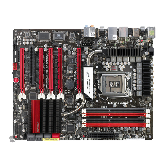
Motherboard overview 2.2.1 Motherboard layout Chapter 2: Hardware information... -
Page 37: Layout Contents
Front panel audio connector (10-1 pin AAFP) 2-43 Digital audio connector (4-1 pin SPDIF_OUT) 2-43 RC Bluetooth connector (12-1 pin RC_Bluetooth) 2-34 Refer to 2.9 Connectors for more information about rear panel connectors and internal connectors. ROG Maximus III Extreme... -
Page 38: Placement Direction
2.2.3 Placement direction When installing the motherboard, ensure that you place it into the chassis in the correct orientation. The edge with external ports goes to the rear part of the chassis as indicated in the image below. 2.2.4 Screw holes Place nine (9) screws into the holes indicated by circles to secure the motherboard to the chassis. -
Page 39: Central Processing Unit (Cpu)
ASUS will shoulder the cost of repair only if the damage is shipment/transit-related. • Keep the cap after installing the motherboard. ASUS will process Return Merchandise Authorization (RMA) requests only if the motherboard comes with the cap on the LGA1156 socket. - Page 40 Lift the load lever in the direction of the arrow until the load plate is completely lifted. Load plate Remove the PnP cap from the CPU socket by lifting the tab only. PnP cap Cap tab Position the CPU over the socket, ensuring that the gold triangle is on the bottom-left corner of the socket, CPU notches...
- Page 41 Close the load plate (A), and then push down the load lever (B), ensuring that the front edge of the load plate slides under the retention knob (C). Insert the load lever under the retention tab. ROG Maximus III Extreme 2-11...
-
Page 42: Installing The Cpu Heatsink And Fan
2.3.2 Installing the CPU heatsink and fan The Intel LGA1156 processor requires a specially designed heatsink and fan ® assembly to ensure optimum thermal condition and performance. • When you buy a boxed Intel processor, the package includes the CPU fan ®... -
Page 43: Uninstalling The Cpu Heatsink And Fan
Rotate each fastener counterclockwise. Pull up two fasteners at a time in a diagonal sequence to disengage the heatsink and fan assembly from the motherboard. Carefully remove the heatsink and fan assembly from the motherboard. ROG Maximus III Extreme 2-13... -
Page 44: System Memory
System memory 2.4.1 Overview The motherboard comes with four Double Data Rate 3 (DDR3) Dual Inline Memory Modules (DIMM) sockets. A DDR3 module has the same physical dimensions as a DDR2 DIMM but is notched differently to prevent installation on a DDR2 DIMM socket. DDR3 modules are developed for better performance with less power consumption. -
Page 45: Memory Configurations
• According to Intel spec definition, DDR3-1600 is supported for one DIMM per channel only. ASUS exclusively provides two DDR3-1600 DIMM support for each memory channel. • According to Intel CPU spec, DIMM voltage below 1.65V is recommended to protect the CPU. - Page 46 Maximus III Extreme Motherboard Qualified Vendors Lists (QVL) DDR3-2133MH�� capability 3-2133MHz capability -2133MHz capability Vendor Part No. Size Chip NO. Timing Voltage DIMM socket support Dimm(Bios) (Optional) G.SKILL F3-17066CL9T-6GB-T 6144MB Heat-Sink Package 9-9-9-24 1.65 • • (Kit of 3) (1066-8-7-7-20) Maximus III Extreme Motherboard Qualified Vendors Lists (QVL) DDR3-2000MH��...
- Page 47 Maximus III Extreme Motherboard Qualified Vendors Lists (QVL) DDR3-1800MH�� capability 3-1800MHz capability -1800MHz capability Vendor Part No. Size Chip NO. Timing Voltage DIMM socket Lable(Bios) support (Optional) Apacer 78.0AGCD-CDZ(XMP) 2048MB(Kit of 2) SS Heat-Sink Package 8-8-8-24 • • (1800-8-8-8-24) CORSAIR...
-
Page 48: Memory Configuration
• C*: Supports four modules inserted into both the yellow and black slots as two pairs of dual-channel memory configuration. Visit the ASUS website at www.asus.com for the latest QVL. 2-18 Chapter 2: Hardware information... - Page 49 Maximus III Extreme Motherboard Qualified Vendors Lists (QVL) DDR3-1333MH�� capability 3-1333MHz capability -1333MHz capability Vendor Part No. Size Chip Chip NO. Timing Voltage DIMM socket Brand Dimm(Bios) support (Optional) A-DATA AD133301GOU 1024MB SS A-DATA AD30908C8D-15IG 1333-9-9-9-24 • • • A-DATA...
- Page 50 Maximus III Extreme Motherboard Qualified Vendors Lists (QVL) DDR3-1333MH�� capability 3-1333MHz capability -1333MHz capability MICRON MT8JTF12864AY-1G4BYES 1024MB SS MICRON Z9HWR (1333-9-9-9-24) • • MICRON MT8JTF12864AZ-1G4F1 1024MB SS MICRON 9FF22 D9KPT 9(1066-8-8-8-20) • • • MICRON MT16JTF25664AZ-1G4F1 2048MB DS MICRON 9FF22 D9KPT 9(1066-8-8-8-20) •...
- Page 51 Maximus III Extreme Motherboard Qualified Vendors Lists (QVL) DDR3-1333MH�� capability 3-1333MHz capability -1333MHz capability Patriot PVS34G1333LLK 4096MB DS N/A Heat-Sink Package 7-7-7-20 • • (Kit of 2) (1066-7-7-7-20) Patriot PVT36G1333ELK 6144MB DS N/A Heat-Sink Package 9-9-9-24 1.65 • • •...
-
Page 52: Installing A Dimm
2.4.3 Installing a DIMM Ensure to unplug the power supply before adding or removing DIMMs or other system components. Failure to do so may cause severe damage to both the motherboard and the components. DIMM notch Unlock a DIMM socket by pressing the retaining clip outward. -
Page 53: Expansion Slots
IRQ” or that the cards do not need IRQ assignments. Otherwise, conflicts will arise between the two PCI groups, making the system unstable and the card inoperable. Refer to the table on the next page for details. ROG Maximus III Extreme 2-23... -
Page 54: Interrupt Assignments
2.5.3 Interrupt assignments Standard interrupt assignments Priority Standard function System Timer Keyboard Controller – Redirect to IRQ#9 Communications Port (COM1)* IRQ Holder for PCI Steering* Reserved Reserved System CMOS/Real Time Clock IRQ Holder for PCI Steering* IRQ Holder for PCI Steering* IRQ Holder for PCI Steering* Reserved Numeric Data Processor... -
Page 55: Pci Slot
PCI Express specifications. Refer to the figure below for the location of the slot. PCI Express x16_5 slot PCI slot PCI Express x16_4 slot PCI Express x16_3 slot PCI Express x16_2 slot PCI Express x16_1 slot ROG Maximus III Extreme 2-25... - Page 56 • When you install three graphics cards, the PCIE slots support x16, x16 and x8 link. When you install four graphics cards, the PCIE slots support x8 link each. Refer to the following configuration table for installation. Three graphics cards Four graphics cards PCIex16_1 slot PCIex16_2 slot...
-
Page 57: Jumper
You do not need to clear the RTC when the system hangs due to CPU overclocking. With the C.P.R. (CPU Parameter Recall) feature, shut down and reboot the system so the BIOS can automatically reset CPU parameter settings to default values. ROG Maximus III Extreme 2-27... - Page 58 LN2 Mode jumper (3-pin LN2) This jumper functions to help the CPU recover from a frozen condition caused by an extremely low temperature. 2-28 Chapter 2: Hardware information...
-
Page 59: Rc Bluetooth Card
RC Bluetooth is OFF, the normal Bluetooth connection is still available. Bluetooth Connector: Connects the RC_BLUETOOTH connector on the motherboard. RC Bluetooth card installation Locate the RC_Bluetooth connector on the motherboard. Orient the RC_Bluetooth card and firmly install it to the connector. ROG Maximus III Extreme 2-29... -
Page 60: I/O Shield Installation
I/O shield Installation Install the I/O shield to the chassis by snapping it in place from inside. Orient the motherboard and install it to the chassis. Make sure that the motherboard external ports fit the I/O openings. Be cautious when installing the motherboard. The I/O shield edge springs may damage the I/O ports. -
Page 61: Connectors
USB 2.0 ports 7 and 8 ROG Connect port Clear CMOS switch Audio ports To use hot-plug, set the Controller Mode in the BIOS settings to [AHCI] mode. See section 3.5.3 Onboard Devices Configuration for details. ROG Maximus III Extreme 2-31... -
Page 62: Rog Connect Switch And Rc Bluetooth Switch
Press the switch to start to connection. To use USB BIOS FlashBack: Download the latest BIOS from ASUS support website. Rename it M3E.ROM, save it to a USB flash drive and place it in the root directory. Connect the USB flash drive to the ROG Connect port. - Page 63 Refer to the Appendix for the qualified vendor list for the mobile phone before using the RC Bluetooth function. • The RC Bluetooth is designed for the following mobile phone operating systems. Visit the ASUS website at www.asus.com for the latest supported operating system list. Mobile phone OS Version Windows Mobile 6.5/ 6.1/ 6.0 Professional (at display resolution 480*800)
-
Page 64: Audio I/O Connections
2.9.3 Audio I/O connections Audio 2, 4, 6, 8, or 10-channel configuration Headset Port 4-channel 6-channel 8-channel 10-channel 2-channel Additional Light Line In Line In Line In Line In Side Speaker Blue Front Speaker Front Speaker Front Speaker Front Speaker Lime Line Out Pink... - Page 65 Connect to Stereo / 2.1-channel Speakers Connect to 4.1-channel Speakers Connect to 5.1-channel Speakers ROG Maximus III Extreme 2-35...
- Page 66 Connect to 7.1-channel Speakers Connect to 9.1-channel Speakers 2-36 Chapter 2: Hardware information...
-
Page 67: Internal Connectors
Serial ATA hard disk drives. The Serial ATA RAID feature is available only if you are using Windows XP SP2 or later versions. ® When using hot-plug and NCQ, set the Configure SATA as in the BIOS to • [AHCI]. See section 3.4.5 Storage Configuration for details. ROG Maximus III Extreme 2-37... - Page 68 Marvell Serial ATA 6.0 Gb/s connectors (7-pin SATA_6G_1/2 [red]) ® These connectors connect to Serial ATA 6.0 Gb/s hard disk drives via Serial ATA 6.0 Gb/s signal cables. • These connectors are set to Standard IDE mode by default. In Standard IDE mode, you can connect Serial ATA data hard disk drives to these connectors.
- Page 69 Never connect a 1394 cable to the USB connectors. Doing so will damage the motherboard! You can connect the USB cable to ASUS Q-Connector (USB, blue) first, and then install the Q-Connector (USB) to the USB connector onboard. ROG Maximus III Extreme...
- Page 70 OC station connector (8-pin OC_Station) This connector is for ASUS OC Station connection only. Connect one end Connect one end of the supplied data cable to the GP connector on the OC Station and the other end to this connector and USB13 on the motherboard to enjoy easier overclocking.
- Page 71 DO NOT place jumper caps on the fan connectors! If you install two VGA cards, we recommend that you plug the chassis fan cable to the motherboard connector labeled OPT_FAN1/2/3 for better thermal environment. ROG Maximus III Extreme 2-41...
- Page 72 Thermal sensor cable connectors (2-pin OPT_TEMP1/2/3) These connectors are for temperature monitoring. Connect the thermal sensor cables to these connectors and place the other ends to the devices which you want to monitor temperature. The optional fan1/2/3 can work with the temperature sensors for a better cooling effect.
- Page 73 Front Panel Type item in the BIOS setup to [HD Audio]; if you want to connect an AC'97 front panel audio module to this connector, set the item to [AC97]. By default, this connector is set to [HD Audio]. ROG Maximus III Extreme 2-43...
-
Page 74: Atx Power Connectors
Appendix for the certified 500W power supply or above. • If you are uncertain about the minimum power supply requirement for your system, refer to the Recommended Power Supply Wattage Calculator at http://support.asus.com/PowerSupplyCalculator/PSCalculator. aspx?SLanguage=en-us for details. 2-44 Chapter 2: Hardware information... - Page 75 BIOS settings. Pressing the power switch for more than four seconds while the system is ON turns the system OFF. • Reset button (2-pin RESET) This 2-pin connector is for the chassis-mounted reset button for system reboot without turning off the system power. ROG Maximus III Extreme 2-45...
- Page 76 14. ASUS Q-Connector (system panel) Use the ASUS Q-Connector to connect/disconnect the chassis front panel cables. To install the ASUS Q-Connector: Connect the front panel cables to the ASUS Q-Connector. Refer to the labels on the Q-Connector to know the detailed...
-
Page 77: Onboard Switches
This is ideal for overclockers and gamers who continually change settings to enhance system performance. Power-on switch Press the power-on switch to wake/power up the system. Reset switch Press the reset switch to reboot the system. ROG Maximus III Extreme 2-47... - Page 78 GO button Press the GO button before POST to enable MemOK! or press it to quickly load the preset profile (GO_Button file) for temporary overclocking when in BIOS button The motherboard comes with two BIOS. Press the BIOS button to switch BIOS and load different BIOS settings.
- Page 79 When the LN2_Mode jumer does not work and your CPU cannot resume function, press the Q reset button to temporarily stop the power supply to the CPU and help the CPU recover from a frozen condition. ROG Maximus III Extreme 2-49...
-
Page 80: Probeit
2.9.6 ProbeIt The ROG ProbeIt feature provides a nice touch for your convenient and accurate OC settings. No time wasted fumbling around on the complicated motherboard layout, the clearly marked area gives you easier access to the measure points when a multitester is employed for more accurate measurements during your busy overclocking work. -
Page 81: 2.10 Starting Up For The First Time
No VGA detected short beeps One continuous beep followed by four Hardware component failure short beeps At power on, hold down the <Delete> key to enter the BIOS Setup. Follow the instructions in Chapter 3. ROG Maximus III Extreme 2-51... -
Page 82: 2.11 Turning Off The Computer
2.11 Turning off the computer 2.11.1 Using the OS shut down function If you are using Windows Vista™/ Windows ® ® Click the Start button then select Shut Down. The power supply should turn off after Windows shuts down. ® If you are using Windows ®... -
Page 83: Chapter 3: Bios Setup
This chapter tells how to change the system settings through the BIOS Setup menus. Detailed descriptions of the BIOS parameters are also provided. BIOS setup... - Page 84 Managing and updating your BIOS ..........3-1 BIOS setup program ..............3-6 Extreme Tweaker menu ............... 3-9 Main menu .................. 3-16 Advanced menu ................. 3-21 Power menu ................3-30 Boot menu .................. 3-36 Tools menu ................. 3-40 Exit menu ..................3-44 ROG Maximus III Extreme...
-
Page 85: Managing And Updating Your Bios
® ASUS EZ Flash 2 (Updates the BIOS using a floppy disk or USB flash disk.) ASUS CrashFree BIOS 3 utility: Restores the BIOS using the motherboard support DVD or a USB flash drive when the BIOS file fails or gets corrupted. - Page 86 To update the BIOS through the Internet: desktop by clicking Start Launch the ASUS Update utility from the Windows ® > Programs > ASUS > ASUSUpdate > ASUSUpdate. The ASUS Update main window appears. Select Update BIOS from the Select the ASUS FTP site nearest...
- Page 87 To update the BIOS through a BIOS file: desktop by clicking Start Launch the ASUS Update utility from the Windows ® > Programs > ASUS > ASUSUpdate > ASUSUpdate. The ASUS Update main window appears. Select Update BIOS from a file option from the drop-down menu, then click Next.
-
Page 88: Asus Ez Flash 2 Utility
3.1.2 ASUS EZ Flash 2 utility The ASUS EZ Flash 2 feature allows you to update the BIOS without having to use a DOS-based utility. The EZ Flash 2 utility is built in the BIOS chip so it is accessible by pressing <Alt> + <F2> during the Power-On Self Tests (POST). -
Page 89: Asus Crashfree Bios 3 Utility
3.1.3 ASUS CrashFree BIOS 3 utility The ASUS CrashFree BIOS 3 utility is an auto recovery tool that allows you to restore the BIOS file when it fails or gets corrupted during the updating process. You can restore a corrupted BIOS file using the motherboard support DVD or a USB flash drive that contains the BIOS file. -
Page 90: Bios Setup Program
The BIOS setup screens shown in this section are for reference purposes only, and may not exactly match what you see on your screen. • Visit the ASUS website at www.asus.com to download the latest BIOS file for this motherboard. Chapter 3: BIOS setup... -
Page 91: Bios Menu Screen
At the bottom right corner of a menu screen are the navigation keys for that particular menu. Use the navigation keys to select items in the menu and change the settings. Some of the navigation keys differ from one screen to another. ROG Maximus III Extreme... -
Page 92: Menu Items
3.2.4 Menu items The highlighted item on the menu bar displays the specific items for that menu. For example, selecting Main shows the Main menu items. The other items (Advanced, Power, Boot, and Exit) on the menu bar have their respective menu items. -
Page 93: Extreme Tweaker Menu
[VID] CPU Voltage [Auto] CPU PLL Voltage [Auto] IMC Voltage [Auto] Current Voltage: 1.058V PCH Temperature: 38˚C/100˚F PCH Voltage [Auto] Current Voltage: 1.535V DRAM Voltage [Auto] DRAM DATA REF Voltage on CHA [Auto] DRAM CTRL REF Voltage on CHA [Auto] ←→ Select Screen DRAM DATA REF Voltage on CHB [Auto] ↑↓ Select Item DRAM CTRL REF Voltage on CHB [Auto] +- Change Option F1 General Help Spread Spectrum and Clock Skew F10 Save and Exit CPU Spread Spectrum [Auto] ESC Exit PCIE Spread Spectrum [Auto] ------------------------------------------------- ASUS O.C. Profile v02.61 (C)Copyright 1985-2009, American Megatrends, Inc. ROG Maximus III Extreme... -
Page 94: Cpu Level Up [Auto]
3.3.1 CPU Level Up [Auto] Allows you to select a CPU level, and the related parameters will be automatically adjusted according to the selected CPU level. If you want to manually configure the settings in detail, set Ai Overclock Tuner to [Manual] after selecting a CPU level. Configuration options: [Auto] [i3-530-2.93G] [i3-540-3.06G] [i5-650-3.2G] 3.3.2 Memory Level Up [Auto]... -
Page 95: Cpu Ratio Setting [Auto]
OC Tuner automatically overclocks the frequency and voltage of CPU and DRAM. Choose [Good Performance] or [Better Performance] as a stable setting for daily use. Choose [Turbo Profile] as an advanced overclocking setting for special purposes. Configuration options: [Turbo Profile] ROG Maximus III Extreme 3-11... -
Page 96: Dram Timing Control
3.3.13 DRAM Timing Control The configuration options for some of the following items vary depending on the depending on the DIMMs you install on the motherboard. 1st Information: 9-9-9-24-4-74-10-5-20 The values vary depending on your settings of the following sub-items: DRAM CAS# Latency [Auto] Configuration options: [Auto] [3 DRAM Clock] [4 DRAM Clock] –... -
Page 97: Cpu Clock Amplitude [Auto]
Adjusting this item may help enhancing BCLK overclocking ability. You may need to adjust the CPU Clock Skew item at the same time. Configuration options: [Auto] [Normal] [Delay 100ps]–[Delay 1500ps] 3.3.18 Extreme OV [Disabled] [Enabled] Enables the Extreme OV function. [Disabled] Disables this function. ROG Maximus III Extreme 3-13... -
Page 98: Cpu Vltage Ocp [Enabled]
3.3.19 CPU Vltage OCP [Enabled] Configuration options: [Disabled] [Enabled] 3.3.20 PWM VGD [Auto] Configuration options: [Auto] [6V] [7V] [8V] [9V] [10V] 3.3.22 CPU Load-Line Calibration [Auto] Load-Line Calibration [Auto] Allows you to select the CPU Load-Line mode. [Auto] BIOS automatically adjust the voltage. [Disabled] Follows Intel specifications. -
Page 99: Dram Voltage [Auto]
[Auto] Sets to [Auto] for EMI control. 3.3.32 PCIE Spread Spectrum [Auto] [Disabled] Enhances the PCIE overclocking ability [Auto] Sets to [Auto] for EMI control. 3.3.33 ASUS O.C. Profile Refer to page 3-40—3-41 for details. ROG Maximus III Extreme 3-15... -
Page 100: Main Menu
Main menu When you enter the BIOS Setup program, the Main menu screen appears, giving you an overview of the basic system information. Refer to section 3.2.1 BIOS menu screen for information on the menu screen items and how to navigate through them. BIOS SETUP UTILITY Extreme Tweaker Main Advanced Power Boot Tools Exit Use [ENTER], [TAB]... -
Page 101: Sata 1-6
Enables or disables the LBA (Logical Block Addressing) mode. [Auto] Select [Auto] to enable the LBA mode (Logical Block Addressing mode) if the device supports this mode, and if the device was not previously formatted with LBA mode disabled. [Disabled] Disable this function. ROG Maximus III Extreme 3-17... - Page 102 Block (Multi-Sector Transfer) M [Auto] Enables or disables data multi-sectors transfers. [Auto] When set to [Auto], the data transfer from and to the device occurs multiple sectors at a time if the device supports multi-sector transfer feature. [Disabled] When set to [Disabled], the data transfer from and to the device occurs one sector at a time.
-
Page 103: Storage Configuration
Disables or enables device write protection. This will be effective only if the device is accessed through BIOS. Configuration option: [Disabled] [Enabled] IDE Detect Time Out (Sec) [35] Selects the time out value for detecting ATA/ATAPI devices. Configuration options: [0] [5] [10] [15] [20] [25] [30] [35] ROG Maximus III Extreme 3-19... -
Page 104: Ahci Configuration
3.4.6 AHCI Configuration This menu is the section for AHCI configuration. It appears only when you set the item Configure SATA as from the sub-menu of SATA Configuration to [AHCI]. BIOS SETUP UTILITY Main AHCI Settings While entering setup, BIOS auto detects SATA Port1 [Not Detected] the presence of SATA Port2 [Not Detected] SATA devices. This SATA Port3 [Not Detected] displays the status SATA Port4 [Not Detected] of auto detection of... -
Page 105: Advanced Menu
Hardware Prefetcher [Enabled] ESC Exit Adjacent Cache Line Prefetch [Enabled] Max CPUID Value Limit [Disabled] v02.61 (C)Copyright 1985-2009, American Megatrends, Inc. Scroll down to display the following items: Intel(R) Virtualization Tech [Enabled] CPU TM Function [Enabled] Execute-Disable Bit Capability [Enabled] ←→ Select Screen Intel(R) HT Technology [Enabled] *Active Processor Cores [All] ↑↓ Select Item +- Change Option A20M [Disabled] F1 General Help *Intel(R) SpeedStep(TM) Tech [Enabled] F10 Save and Exit Intel(R) C-STATE Tech [Enabled] ESC Exit C State package limit setting [Auto] v02.61 (C)Copyright 1985-2009, American Megatrends, Inc. ROG Maximus III Extreme 3-21... - Page 106 CPU Ratio Setting [Auto] Allows you to adjust the ratio between CPU Core Clock and BCLK Frequency. Use the <+> and <-> keys to adjust the value. The valid value ranges differently according to your CPU model. C1E Support [Disabled] [Enabled] Enables the C1E support function.
- Page 107 This item appears only when you set the Intel(R) C-STATE Tech item to [Enabled]. We recommend that you set this item to [Auto] for BIOS to automatically detect the C-State mode supported by your CPU. Configuration options: [Auto] [C1] [C3] [C6] ROG Maximus III Extreme 3-23...
-
Page 108: Chipset
3.5.2 Chipset The Chipset menu allows you to change the advanced chipset settings. Select an item then press <Enter> to display the sub-menu. BIOS SETUP UTILITY Advanced Advanced Chipset Settings Configure North Bridge features WARNING: Setting wrong values in below sections may cause system to malfunction. North Bridge Configuration Uncore Configuration BIOS SETUP UTILITY Advanced Uncore Chipset Configuration Set the ECC options for cache and dram IMC Type : Clarkdale... -
Page 109: Onboard Device Configuration
AHCI (Advabced Host Controller Interface). The AHCI allows the onboard storage driver to enable advanced Serial ATA features that increases storage performance on random workloads by allowing the drive to internally optimize the order of commands. ROG Maximus III Extreme 3-25... - Page 110 Marvell 9123 Controller [IDE Mode] [Disabled] Disables the Marvell 9123 controller. [IDE Mode] Set to [IDE Mode] when you want to use the Serial ATA hard disk drives as Parallel ATA physical storage devices. [AHCI Mode] Set to [AHCI] when you want the SATA hard disk drives to use the AHCI (Advabced Host Controller Interface).
-
Page 111: Usb Configuration
Enables the support for USB devices on legacy operating systems (OS). [Disabled] Disables the function. BIOS EHCI Hand-off [Enabled] [Enabled] Enables the support for operating systems without an EHCI hand-off feature. [Disabled] Disables the function. ROG Maximus III Extreme 3-27... -
Page 112: Led Control
3.5.5 LED Control The LED Control menu items allow you to change the advanced settings for the onboard LEDs. Take caution when changing the settings of the LED Control menu items. Incorrect field values can cause the system to malfunction. BIOS SETUP UTILITY Advanced LED Control... -
Page 113: Irog Configuration
ESC Exit v02.61 (C)Copyright 1985-2009, American Megatrends, Inc. ROG Connect [Enabled] Allows you to enable or disable the ROG Connect function. Configuration options: [Enabled] [Disabled] RC Poster Mode [String] RC Poster describes what occurs during the POST. Configuration options: [String] [Code] ROG Maximus III Extreme 3-29... -
Page 114: Power Menu
Power menu The Power menu items allow you to change the settings for the Advanced Power Management (APM). Select an item then press <Enter> to display the configuration options. BIOS SETUP UTILITY Extreme Tweaker Main Main Advanced Power Boot Tools Exit Advanced Select the ACPI state Suspend Mode [Auto] used for System Repost Video on S3 Resume [No] Suspend. ACPI 2.0 Support [Disabled] ACPI APIC Support... -
Page 115: Acpi Apic Support [Enabled]
The system goes into off state after an AC power loss. [Power On] The system goes into on state after an AC power loss. [Last State] The system goes into either off or on state, whatever the system state was before the AC power loss. ROG Maximus III Extreme 3-31... - Page 116 Power On By RTC Alarm [Disabled] Allows you to enable or disable RTC to generate a wake event. When this item is set to [Enabled], the items RTC Alarm Date/ RTC Alarm Hour/ RTC Alarm Minute/ RTC Alarm Second will become user-configurable with set values. Configuration options: [Disabled] [Enabled] [Disabled] Disables RTC to generate a wake event.
-
Page 117: Hardware Monitor
Allows you to set the temperature over which the system automatically shuts down when any of the thermal sensor cables connected to the motherboard detects device overheat to protect the device from damage. Configuration options: [Disabled] [70ºC] [80ºC] [90ºC] [100ºC] [100ºC] ROG Maximus III Extreme 3-33... -
Page 118: Fan Speed Control
Fan Speed Monitor CPU FAN; Chassis FAN1/2/3; Power FAN Speed OPT FAN1/2/3 Speed [xxxxRPM] or [Ignored] / [N/A] The onboard hardware monitor automatically detects and displays the CPU fan, chassis fan, power fan, and optional fan speed in rotations per minute (RPM). - Page 119 OPTFan1/2/3 Full Speed Temp [60˚C] Allows you to set the temperature at which the power fan rotates at full speed. This item appears when the OPTFan1/2 Control item is set to [User Mode]. Configuration options: [60˚C] [70˚C] [80˚C] [90˚C] ROG Maximus III Extreme 3-35...
-
Page 120: Boot Menu
Boot menu The Boot menu items allow you to change the system boot options. Select an item then press <Enter> to display the sub-menu. BIOS SETUP UTILITY Extreme Tweaker Main Main Advanced Power Boot Tools Exit Advanced Power Specifies the Boot Boot Settings Device Priority sequence. Boot Device Priority A virtual floppy disk Boot Settings Configuration drive (Floppy Drive B: Security... -
Page 121: Boot Settings Configuration
Enables the full screen logo display feature. [Disabled] Disables the full screen logo display feature. Set this item to [Enabled] to use the ASUS MyLogo3™ feature. AddOn ROM Display Mode [Force BIOS] Sets the display mode for option ROM. [Force BIOS] [Keep Current] . -
Page 122: Security
3.7.3 Security The Security menu items allow you to change the system security settings. Select an item then press <Enter> to display the configuration options. BIOS SETUP UTILITY Boot <Enter> to change Security Settings password. <Enter> again to Supervisor Password :Not Installed disabled password User Password :Not Installed Change Supervisor Password Change User Password ←→ Select Screen ↑↓ Select Item Enter Go to Sub Screen F1 General Help F10 Save and Exit... -
Page 123: Change User Password
When set to [Setup], BIOS checks for user password when accessing the Setup utility. When set to [Always], BIOS checks for user password both when accessing Setup and booting the system. Configuration options: [Setup] [Always] ROG Maximus III Extreme 3-39... -
Page 124: Tools Menu
Tools menu The Tools menu items allow you to configure options for special functions. Select an item then press <Enter> to display the sub-menu. BIOS SETUP UTILITY Extreme Tweaker Main Advanced Power Boot Tools Exit ASUS O.C. Profile GO_Button File AI NET 2 ASUS EZ Flash 2 ←→ Select Screen ↑↓ Select Item Enter Go to Sub Screen F1 General Help F10 Save and Exit ESC Exit v02.61 (C)Copyright 1985-2009, American Megatrends, Inc. 3.8.1 ASUS O.C. - Page 125 DO NOT shut down or reset the system while updating the BIOS to prevent the system boot failure! • We recommend that you update the BIOS file only coming from the same memory/CPU configuration and BIOS version. • Only the CMO file can be loaded. ROG Maximus III Extreme 3-41...
-
Page 126: Go_Button File
3.6.2 GO_Button File This menu allows you to set the GO_Button files, and load the desired GO_Button file. BIOS SETUP UTILITY Tools GO_Button File Save GO_Button File Save File to: [None] Load File From: [None] FSB Frequency Controller [Auto] CPU Voltage [Auto] CPU PLL Voltage [Auto] IMC Voltage [Auto] PCH Voltage [Auto] DRAM Voltage [Auto] ←→ Select Screen ↑↓ Select Item +- Change Option... -
Page 127: Asus Ez Flash 2
3.6.4 ASUS EZ Flash 2 Allows you to run ASUS EZ Flash 2. When you press <Enter>, a confirmation message appears. Use the left/right arrow key to select between [Yes] or [No], then press <Enter> to confirm your choice. For more details, refer to section 3.1.2 ASUS EZ Flash 2 utility. -
Page 128: Exit Menu
Exit menu The Exit menu items allow you to load the optimal or failsafe default values for the BIOS items, and save or discard your changes to the BIOS items. BIOS SETUP UTILITY Main Extreme Tweaker Advanced Power Boot Tools Exit Exit system setup after Exit Options saving the changes. F10 key can be used for Exit & Save Changes this operation. Exit & Discard Changes Discard Changes Load Setup Defaults ←→ Select Screen ↑↓ Select Item... -
Page 129: Chapter 4: Software Support
This chapter describes the contents of the support DVD that comes with the motherboard package and the software. Software support... - Page 130 Chapter summary Installing an operating system ........... 4-1 Support DVD information ............4-1 Software information ..............4-9 RAID configurations ..............4-24 Creating a RAID driver disk ............4-29 ROG Maximus III Extreme...
-
Page 131: Installing An Operating System
The contents of the support DVD are subject to change at any time without notice. Visit the ASUS website at www.asus.com for updates. 4.2.1 Running the support DVD Place the support DVD to the optical drive. -
Page 132: Drivers Menu
Installs Realtek LAN driver. VIA Audio Driver Installs the VIA Audio driver. ASUS TurboV EVO Installs ASUS TurboV, the advanced overclocking tool for extreme O.C. record. Browser Configuration Utility Installs the Browser Configuration utility. USB 2.0 Driver Installs USB 2.0 driver. -
Page 133: Utilities Menu
The Utilities menu shows the applications and other software that the motherboard supports. ASUS Update The ASUS Update utility allows you to update the motherboard BIOS in Windows ® environment. This utility requires an Internet connection either through a network or an Internet Service Provider (ISP). -
Page 134: Make Disk Menu
4.2.4 Make disk menu The Make disk menu contains items to create the Intel and JMicron RAID driver disk. Intel AHCI/RAID Driver Allows you to create an Intel AHCI/RAID Driver disk. JMicron JMB36X AHCI Driver Allows you to create a JMicron AHCI Driver disk. 4.2.5 Manual menu The Manuals menu contains a list of supplementary user manuals. -
Page 135: Video Menu
ROG users’ outstanding performances with ROG motherboards. 4.2.7 ASUS Contact information Click the Contact tab to display the ASUS contact information. You can also find this information on the inside front cover of this user guide. ROG Maximus III Extreme... -
Page 136: Other Information
4.2.8 Other information The icons on the top right corner of the screen give additional information on the motherboard and the contents of the support DVD. Click an icon to display the specified information. Motherboard Info Displays the general specifications of the motherboard. Browse this DVD Displays the support DVD contents in graphical format. - Page 137 Filelist Displays the contents of the support DVD and a brief description of each in text format. ROG Maximus III Extreme...
-
Page 138: Obtaining The Software Manuals
Acrobat Reader from the Utilities menu before opening the files. ® ® Click the Manual tab. Click ASUS Motherboard Utility Guide from the manual list on the left. The Manual folder of the support DVD appears. Double- click the folder of your selected software. -
Page 139: Software Information
Click on the icon to display the VIA HD Audio Deck. VIA HD Audio Deck for Windows Vista™ / Windows 7™ ® ® Volume control Minimize button Output source select Output jack indicator Fold / unfold Software interface information Configuration options Advanced Options ROG Maximus III Extreme... - Page 140 VIA HD Audio Deck for Windows XP Display panel and volume control Minimize button Configuration options Control settings window Refer to the software manual in the support DVD or visit the ASUS website at www.asus.com for detailed software configuration. 4-10 Chapter 4: Software support...
-
Page 141: Asus Pc Probe Ii
To launch the PC Probe II from the Windows ® > ASUS > PC Probe II > PC Probe II v1.xx.xx. The PC Probe II main window appears. After launching the application, the PC Probe II icon appears in the Windows ®... - Page 142 Button Function Opens the Configuration window Opens the Report window Opens the Desktop Management Interface window Opens the Peripheral Component Interconnect window Opens the Windows Management Instrumentation window Opens the hard disk drive, memory, CPU usage window Shows/Hides the Preference section Minimizes the application Closes the application Sensor alert...
- Page 143 Click to clicking the or buttons. You can increase also adjust the threshold values value using the Config window. Click to You cannot adjust the sensor decrease value threshold values in a small monitoring panel. ROG Maximus III Extreme 4-13...
- Page 144 Monitoring sensor alert The monitor panel turns red when a component value exceeds or is lower than the threshold value. Refer to the illustrations below. Small display Large display WMI browser Click to display the WMI (Windows Management Instrumentation) browser. This browser displays various Windows®...
- Page 145 Click a hard disk drive to display the information on the right panel. The pie chart at the bottom of the window represents the used (blue) and the available HDD space. ROG Maximus III Extreme 4-15...
- Page 146 Memory usage The Memory tab shows both used and available physical memory. The pie chart at the bottom of the window represents the used (blue) and the available physical memory. Configuring PC Probe II Click to view and adjust the sensor threshold values. The Config window has two tabs: Sensor/Threshold and Preference.
-
Page 147: Asus Ai Suite
Start > All Programs > To launch AI Suite from the Windows ® ASUS > AI Suite > AI Suite v1.xx.xx. The AI Suite main window appears. After launching the application, the AI Suite icon appears in the Windows ®... - Page 148 Other feature buttons Click on right corner of the main window to open the monitor window. Displays the CPU/ system temperature, CPU/memory/PCIE voltage, and CPU/ chassis fan speed Displays the FSB/CPU frequency Click on right corner of the expanded window to switch the temperature from degrees Centigrade to degrees Fahrenheit.
-
Page 149: Asus Fan Xpert
4.3.4 ASUS Fan Xpert Asus Fan Xpert allows you to adjust both the CPU and chassis fan speeds according to different ambient temperatures and your PC’s system loading. The various fan profiles offer flexible controls of fan speeds to achieve a quiet and cool system environment. -
Page 150: Cpu Level Up
4.3.5 CPU Level Up The CPU Level Up allows you to overclock immediately with OC profile presets in WIndows environment without the hassle of entering BIOS. ® After installing AI Suite from the bundled Support DVD, launch the utility by double- clicking the AI Suite icon in the Windows in the Windows notification area and click the CPU... -
Page 151: Turbov Evo
EVO icon on the Windows notification area. Click on the icon to display the TurboV EVO control panel. Refer to the software manual in the support DVD or visit the ASUS website at www.asus.com for detailed software configuration. Using ASUS TurboV... -
Page 152: Rog Connect
4.3.7 ROG Connect ROG Connect allows you to monitor and adjust your system through your another PC or laptop. RC TweakIt To use RC TweaakIt: Connect the provided ROG Connect cable to your system and your another PC or laptop. Double-click the RC TweakIt shortcut on the desktop to activate the function.\ Use the sliders and buttons to monitor or adjust your system. - Page 153 ROG Connect cable. RC Diagram RC Diagram allows you to monitor and record your system status. RC BIOS FlashBack RC BIOS FlashBack allows you to switch the BIOS and update the latest BIOS. ROG Maximus III Extreme 4-23...
-
Page 154: Raid Configurations
RAID configurations The motherboard comes with the Intel P55 chipset that allows you to configure ® Serial ATA hard disk drives as RAID sets. The motherboard supports the following RAID configurations: RAID 0, RAID 1, RAID 10 and RAID 5. •... -
Page 155: Installing Serial Ata Hard Disks
Turn on the system. During POST, press <Ctrl> + <I> to display the utility main menu. Intel(R) Matrix Storage Manager option ROM v8.9.0.1014 PCH-D wRAID5 Copyright(C) 2003-09 Intel Corporation. All Rights Reserved. [ MAIN MENU ] 1. Create RAID Volume 3. Reset Disks to Non-RAID 2. Delete RAID Volume 4. Recovery Volume Options 5. Exit [ DISK/VOLUME INFORMATION ] RAID Volumes: None defined. Physical Disks: Port Drive Model Serial # Size Type/Status(Vol ID) 0 ST3160812AS 9LS0HJA4 149.0GB Non-RAID Disk 1 ST3160812AS 9LS0F4HL 149.0GB Non-RAID Disk 2 ST3160812AS 3LS0JYL8 149.0GB Non-RAID Disk 3 ST3160812AS 9LS0BJ5H 149.0GB Non-RAID Disk [↑↓]-Select [ESC]-Exit [ENTER]-Select Menu ROG Maximus III Extreme 4-25... -
Page 156: Creating A Raid Volume
The navigation keys at the bottom of the screen allow you to move through the menus and select the menu options. The RAID BIOS setup screens shown in this section are for reference only and may not exactly match the items on your screen. The utility supports maximum four hard disk drives for RAID configuration. - Page 157 When the Create Volume item is selected, press <Enter>. The following warning message appears. WARNING: ALL DATA ON SELECTED DISKS WILL BE LOST. Are you sure you want to create this volume? (Y/N): Press <Y> to create the RAID volume and return to the main menu, or <N> to go back to the CREATE VOLUME menu. ROG Maximus III Extreme 4-27...
-
Page 158: Deleting A Raid Set
Deleting a RAID set Take caution when deleting a RAID set. You will lose all data on the hard disk drives when you delete a RAID set. To delete a RAID set From the utility main menu, select 2. Delete RAID Volume and press <Enter>. -
Page 159: Creating A Raid Driver Disk
Go to the Make Disk menu, and then click Intel AHCI/RAID Driver to create an Intel RAID driver disk. ® Select USB floppy disk drive as the destination disk. Follow the succeeding screen instructions to complete the process. Write-protect the floppy disk to avoid a computer virus infection. ROG Maximus III Extreme 4-29... -
Page 160: Installing The Raid Driver During Windows ® Os Installation
4.5.3 Installing the RAID driver during Windows ® installation To install the RAID driver for Windows ® During the OS installation, the system prompts you to press the F6 key to install third-party SCSI or RAID driver. Press <F6>, and then insert the floppy disk with RAID driver into the USB floppy disk drive. - Page 161 Browse the contents of the RAID driver disk to locate the file txtsetup.oem. Double-click the file. A window appears, allowing you to select the program for opening the oem file. Use Notepad to open the file. ROG Maximus III Extreme 4-31...
- Page 162 Find the [HardwareIds.scsi.iaAHCI_PCH] and [HardwareIds.scsi.iastor_8R9R10RDOPCH] sections in the txtsetup.oem file. Type the following line to the bottom of the two sections: id = “USB\VID_xxxx&PID_xxxx”, “usbstor” [HardwareIds.scsi.iaAHCI_PCH] id= “PCI\VEN_8086&DEV_3A22&CC_0106”,”iaStor” id= “USB\VID_03EE&PID_6901”, “usbstor” [HardwareIds.scsi.iaStor_8R9R10RDOPCH] id= “PCI\VEN_8086&DEV_3A22&CC_0106”,”iaStor” id= “USB\VID_03EE&PID_6901”, “usbstor” Add the same line to both sections. The VID and PID vary with different vendors. 10.
-
Page 163: Chapter 5: Ati Crossfirex™ Technology Support
This chapter describes how to install and configure ATI CrossFireX™ graphics ® cards. CrossFireX™ ® technology support... - Page 164 Chapter summary CrossFireX™ technology ............ 5-1 ® NVIDIA SLI™ technology ............5-5 ® ROG Maximus III Extreme...
-
Page 165: Ati ® Crossfirex™ Technology
For Windows XP, go to Control Panel > Add/Remove Programs. For Windows Vista, go to Control Panel > Programs and Features. Select your current graphics card driver/s. For Windows XP, select Add/Remove. For Windows Vista, select Uninstall. Turn off your computer. ROG Maximus III Extreme... -
Page 166: Installing Crossfirex Graphics Cards
5.1.3 Installing CrossFireX graphics cards The following pictures are for reference only. The graphics cards and the motherboard layout may vary with models, but the installation steps remain the same. Prepare two CrossFireX-ready graphics cards. Insert the two graphics card into the PCIEX16 slots. -
Page 167: Installing The Device Drivers
Windows notification area and select Cayalist Control Center. The Catalyst Control Center Setup Assistant appears when the system detects the existance of multi- graphics cards. Click Go to continue to the Catalyst Control Center Advanced View window. ROG Maximus III Extreme... - Page 168 Enabling CrossFireX settings In the Catalyst Control Center window, click Graphics Settings > CrossFireX > Configure. From the Graphics Adapter list, select the graphics card to act as the display GPU. Select Enable CrossFireX. Click Apply, and then click OK to exit the window.
-
Page 169: Nvidia ® Sli™ Technology
PCIEX16 slots, refer to Chapter 2 in this user manual for the locations of the PCIEX16 slots recommended for multi-graphics card installation. Ensure that the cards are properly seated on the slots. ROG Maximus III Extreme... -
Page 170: Installing The Device Drivers
Align and firmly insert the SLI bridge connector to the goldfingers on each graphics card. Ensure that the connector is firmly in place. Connect two independent auxiliary power sources from the power supply to the two graphics cards separately. Connect a VGA or a DVI cable to the graphics card. SLI bridge Goldfingers 5.2.3... - Page 171 B1. If you cannot see the NVIDIA Control Panel item in step (A), select Personalize. B2. From the Personalization window, select Display Settings. B3. From the Display Settings dialog box, click Advanced Settings. ROG Maximus III Extreme...
- Page 172 B4. Select the NVIDIA GeForce tab, and then click Start the NVIDIA Control Panel. B5. The NVIDIA Control Panel window appears. Enabling SLI settings From the NVIDIA Control Panel window, select Set SLI Configuration. Click Enable SLI and set the display for viewing SLI rendered content.
-
Page 173: Appendix: Reference Information
This appendix includes additional information that you may refer to when configuring the motherboard. Reference information Appendix:... - Page 174 Chapter summary Debug code table .................A-1 Qualified Vendors Lists (QVL) for BIOS FlashBack ....A-4 Qualified Vendors Lists (QVL) for RC Bluetooth .......A-4 Qualified Vendors Lists (QVL) for 500W Power Supply or above ..................A-5 ROG Maximus III Extreme...
-
Page 175: Debug Code Table
4. Measure CPU speed. 5. Invoke video BIOS. VGA BIOS Initialize VGA BIOS 1. Initialize multi-language TESTVRAM 2. Put information on screen display, including BIOS logo, CPU type, CPU speed . RESET KB Reset keyboard. ROG Maximus III Extreme... - Page 176 Debug code table Code Description 8254TEST Test 8254 8259MSK1 Test 8259 interrupt mask bits for channel 1. 8259MSK2 Test 8259 interrupt mask bits for channel 2. 8259TEST Test 8259 functionality. COUNTMEM Calculate total memory by testing the last double word of each 64K page. 1.
- Page 177 1. Build MP table 2. Build & update ESCD UPDT DMI 3. Set CMOS century to 20h or 19h 4. Load CMOS time into DOS timer tick 5. Build MSIRQ routing table. INT 19H Boot attempt (INT 19h) ROG Maximus III Extreme...
-
Page 178: Qualified Vendors Lists (Qvl) For Bios Flashback
CMOS Transcend TS16GJFV60 CMOS 16GB iMate combo driver CMOS Qualified Vendors Lists (QVL) for RC Bluetooth Brand Model Sony Ericsson XPERIA X1 ASUS P835 Samsung I8000 Nokia Visit the ASUS website at www.asus.com for the latest QVL. Appendix: Reference information... -
Page 179: Qualified Vendors Lists (Qvl) For 500W Power Supply Or Above
Thermaltake W0132RE 3.5A Win7-64timate 1000W 80 PLUS Thermaltake W0171 3.5A Win7-64timate 1500W 80 PLUS Visit the ASUS website at www.asus.com for the latest QVL. Manufacturer ASUSTek COMPUTER INC. Address, City No. 150, LI-TE RD., PEITOU, TAIPEI 112, TAIWAN R.O.C Country TAIWAN... - Page 180 Appendix: Reference information...