Table of Contents
Advertisement
Use & Care Guide
Manual de Uso y Cuidado
English / Español
Model/Modelo: 139.01566310
Item / Artículo: 640-04921798-7
Kenmore
®
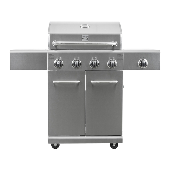
Liquid Propane Gas Grill
Parrilla de LP gas
3027951
P/N
Rev4 11/12
Sears Brands Management Corporation
Hoffman Estates, IL 60179 U.S.A.
www.kenmore.com
www.sears.com
www.kmart.com
®
Advertisement
Table of Contents

Related Manuals for Kenmore 139.01566310


Summary of Contents for Kenmore 139.01566310
- Page 1 Use & Care Guide Manual de Uso y Cuidado English / Español Model/Modelo: 139.01566310 Item / Artículo: 640-04921798-7 Kenmore ® Liquid Propane Gas Grill Parrilla de LP gas 3027951 Rev4 11/12 Sears Brands Management Corporation Hoffman Estates, IL 60179 U.S.A.
-
Page 2: Grill Service Center
Installation Safety Precautions • Use grill, as purchased, only with LP (propane) gas and the regulator/valve assembly supplied. A conversion kit must be purchased for use with natural gas. If you smell gas: • Grill installation must conform with local codes, or in their absence of local codes, with either the National Fuel Gas 1. -
Page 3: Table Of Contents
After the first year Kenmore Grill Warranty ......3 from the date of purchase, you are responsible for the labor cost to have it installed. -
Page 4: Use And Care
LP Cylinder USE AND CARE • The LP cylinder used with your grill must meet the following requirements: • Use LP cylinders only with these required measurements: 12" (30.5cm) (diameter) x 18" (45.7 cm) (tall) with 20 lb. (9 kg.) capacity maximum. - Page 5 LP Tank Exchange Connecting Regulator To The LP Tank •Many retailers that sell grills offer you the option of replacing 1. LP tank must be properly secured onto grill. (Refer to your empty LP tank through an exchange service. Use only assembly section.) those reputable exchange companies that inspect, precision 2.
- Page 6 Leak Testing Valves, Hose and Regulator 1. Turn all grill control knobs to OFF. 2. Be sure regulator is tightly connected to LP tank. 3. Completely open LP tank valve by turning OPD hand wheel counterclockwise. If you hear a rushing sound, turn gas off Hold coupling nut and regulator immediately.
- Page 7 Safety Tips Before opening LP cylinder valve, check the coupling nut for tightness. When grill is not in use, turn off all control knobs and LP For Safe Use of Your Grill and to Avoid Serious cylinder valve. Injury: Never move grill while in operation or still hot. •...
- Page 8 4. If ignition does not occur in 5 seconds, turn the burner control off, wait 5 minutes for gas to clear away, and repeat step 3. 5. To light other burners, repeat step 3. NOTE: If ignitor does not work, follow Match Lighting instructions.
-
Page 9: Spider Alert
Storing Your Grill Do not use citrisol, abrasive cleaners, degreasers or a concentrated grill cleaner on plastic parts. Damage to and •Clean cooking grates. failure of parts can result. •Store in dry location. •Porcelain surfaces: Because of glass-like composition, most •When LP cylinder is connected to grill, store outdoors in a residue can be wiped away with baking soda/water solution wellventilated space and out of reach of children. - Page 10 Food Safety Food safety is a very important part of enjoying the outdoor cooking experience. To keep food safe from harmful bacteria, follow these four basic steps: Clean: Wash hands, utensils, and surfaces with hot soapy water before and after handling raw meat and poultry. Separate: Separate raw meats and poultry from ready-to-eat foods to avoid cross contamination.
- Page 11 Gas Requirements Care and Maintenance Time Table Chart LP Gas Frequency Based If your grill is for LP Gas, the regulator supplied is set for Grill Item on Normal Use Cleaning Method an 11-in. water column (WC) and is for use with LP gas only.
-
Page 12: Natural Gas Conversion Kit
Natural gas conversion kit 2. Insert plug and release sleeve. Kenmore Model # 01898 (Manufacturer Part No.: 9141650 ) 3. Push plug until sleeve snaps forward. (Gas will flow automatically. Failure to connect plug properly to socket will inhibit gas flow to the appliance.) - Page 13 Part list detail with graphic: Description Artwork Bottom Panel Assembly Castor Castor with Lock Tank Tray Cart Left side Panel Assembly Cart Right side Panel Assembly Cart Rear Panel...
- Page 14 Cart Beam Assembly Triangle Strengthening Wedge Tank Exclusion Bar Drip Tray Assembly Left side Door Assembly Right side Door Assembly Handle Assembly...
- Page 15 Handle Bezel Handle Screw Cap Door Hinge Hood Handle Hood Handle Bezel Grill Body Assembly...
- Page 16 Side Table Assembly Side Burner Assembly Bezel Knob Knob Igniter Side burner grid...
- Page 17 Heat Diffusers Cooking Grid Warming Rack Drip Cup Door Stop Hardware Tool Kit 5109076 Natural Gas Conversion Kit Not Included, purchase separately 01898...
- Page 18 Hardware Tool Kit: AA. M6*16 Screw BB. M6 Washer CC.M6 Stretchy DD. M5*16 Screw EE.Washer QTY: 57 pcs QTY: 18 pcs Washer QTY: 18pcs 18*6.4*1.5, QTY: 4 pcs QTY: 22 pcs FF. M4*6 Screw GG. M4*10 Screw HH. M5 Blast-proof II.
-
Page 19: Parts List
Parts List: Description Part. No. Description Part. No. Hood Inner Panel CH3017301 Main Burner Ignition Wire CH3017341 Hood Rotation Shaft CH3017302 Rear Burner Ignition Wire 1 CH3017342 Hood Assembly CH3017303 Side Burner Ignition Wire 1 CH3017343 Thermometer CH3017304 1 Ignition Wire CH3017344 2 Name Plate CH3017305... -
Page 20: Parts Diagram
Part Diagram... -
Page 21: Assembly
ASSEMBLY INSTRUCTIONS IMPORTANT: Assemble the grill on a flat level surface. During assembly, check the parts and hardware for correct identification against the list and diagrams on pages 13–18. 1. Casters Attach each locking castor to the back of the bottom panel with 4 AA screws and 4 BB and 4 CC washers as shown below. - Page 22 3. Left and Right Side Panel - Screw 2 AA screws into each side of the bottom panel as shown below. Leave the screw heads protruding approximately 1/8-inch above panel surface. - Insert the holes in each side panel base over the protruding screws on each side of the bottom panel. - Slide the side panels to the back of bottom panel.
- Page 23 5. Cart Beam, Triangle Strengthening Wedge, Tank Exclusion Bar - Screw 2 AA screws into the top front of each side panel as shown below. Leave screw heads protruding approximately 1/8-inch above panel surface. - Slide the 2 notches in each end of the cart beam into place over the protruding screws.. - Tighten the screws to secure the cart beam to the side panels.
- Page 24 7. Hood Handle Attach each end of handle to grill hood with 1 handle bezel, 1 BB washer, 1 CC lock washer and 1 AA screw as shown. Secure tightly. 8. Grill Head - With the aid of an assistant, lift and place grill head onto cart. Make sure that regulator and side burner valve hang outside of cart to the right, and that the 5 thick and 2 thin ignitor wires slip through the opening between the drip tray and front beam to hang inside the cart.
- Page 25 9. Towel Bars - Attach 1 Towel Bar to Side Table with 2 handle bezels, 2 EE washers, 2 CC lock washers and 2 DD screws. - Attach 1Towel Bar to Side Burner with 2 handle bezels, 2 EE washers, 2 CC lock washers and 2 DD screws. 10.
- Page 26 11. Side Burner Tube and Valve - Remove tie wraps from side burner grid, and remove grid from side burner. - Insert side burner valve control stem though side burner control panel. Attach bezel to control panel and valve control with 2 FF screws. - Attach the side burner nozzle support to the underside of the burner bowl with 2 DD screws and 2 HH washers as shown.
- Page 27 13. Igniter Wires - Plug the 6 thick ignitor wires into the 6 sockets in the ignition box. - Plug the 2 thin ignitor wires onto the two connection tabs on the ignition box. 14. Door Handles and Hinges - Attach each Handle to 1 Door with 2 Handle Bezels, 2 Handle Screw Caps and 2 DD screws. - Attach each of 2 Hinges to 1 Door with 2 GG screws as shown.
- Page 28 15. Doors Attach Doors to cart front with 4 GG screws for each Hinge as shown. If the doors are not aligned correctly after assembly, they can be adjusted as follow: Screw#1 is used to adjust the gap between doors and align the door to the cart side panel (see pic 1); Screw#2 is used to adjust the gap between doors and cart side panel (see pic 2) Pic1 Pic2...
- Page 29 17. Install the drip cup into position from the rear of the grill as shown. 18. LP Gas Tank - Unlock the tank tray latch by turning it to the right. - Slide out the tank tray. - Turn the thumb screw at the front of the tray all the way counterclockwise. - Place the LP gas tank into the tray with the tank valve facing to the front.
- Page 30 19. Unscrew ignitor cap from ignition box on side panel as shown. Install 1 AA battery into the ignition box. Replace cap on box. WARNING: DO NOT attempt to store a spare gas tank in the cabinet. DO NOT install the tank in a leaning position.
- Page 31 Problem Possible Cause Corrective Action 1. The ignition wire came off the 1. Reconnect the ignition wire to the electrical electrical igniter. igniter. 2. The distance between the ignition pin and the burner is greater than 2. Loosen the ignition pin and adjust the 0.1-0.2 inch(side burner).
- Page 32 Problem Possible Cause Corrective Action 1. Refill the LP Tank. 1. LP tank is empty. 2. Install the burner correctly. Burner blows out 2. Burner is not aligned with the control valve. 3. Check the gas supply hose and make sure 3.
- Page 33 Problem Possible Cause Corrective Action The propane regulator assembly Please follow these instructions: 1. Make sure incorporates an excess flow device all burners are “OFF”. 2. Open the tank designed to supply the grill with valve and wait 5 minutes. 3. Light the burner Low heat, LP gas sufficient gas flow.
- Page 34 Installation Safety Precautions Medidas de seguridad en la instalación PELIGRO • Use la parrilla tal y como la compró, solo con gas LP (Propano) • Use grill, as purchased, only with LP (propane) gas and the regulator/valve assembly supplied. A conversion kit must y la válvula que viene con el producto.
-
Page 35: Troubleshooting
Después del primer año Kenmore Grill Warranty ......3 Lista de repuestos ..............45-51... - Page 36 Botella LP LP Cylinder USO Y CUIDADO • La botella LP usada en su parrilla debe de cumplir los • The LP cylinder used with your grill must meet the siguientes requisitos. following requirements: • Use botellas LP con las medidas requeridas 12" (30,5cm) •...
- Page 37 LP Tank Exchange Connecting Regulator To The LP Tank Cambio de botella LP Conectar el regulador al tanque LP • Muchos vendedores que venden parrillas le ofrecen la El tanque LP debe de estar asegurado a la •Many retailers that sell grills offer you the option of replacing 1.
- Page 38 Comprobar fugas en las válvulas, manguera y regulador Leak Testing Valves, Hose and Regulator 1) Ponga los pulsadores en OFF. 2) Asegúrese de que el regulador está bien conectado al 1. Turn all grill control knobs to OFF. tanque LP. 3) Abra la válvula del tanque completamente girando la 2.
- Page 39 Consejos de Seguridad Safety Tips ▲ Antes de abrir la válvula de la botella LP, compruebe que ATENCIÓN Before opening LP cylinder valve, check the coupling nut la rosca está bien apretada. for tightness. ▲ Cuando no use la parrilla, cierre todos los pulsadores y la When grill is not in use, turn off all control knobs and LP válvula de la botella LP.
- Page 40 4. Si no se enciende en 5 segundos, apague el quemador, espere 5 minutos para que se vaya el 4. If ignition does not occur in 5 seconds, turn the burner gas acumulado y repita el paso 3. control off, wait 5 minutes for gas to clear away, and repeat 5.
- Page 41 No use citrisol, limpiadores abrasivos, desengrasantes o Guardar la Parrilla Do not use citrisol, abrasive cleaners, degreasers or a Storing Your Grill • Limpie las rejillas de cocción un limpiador de parrillas concentrado en partes de concentrated grill cleaner on plastic parts. Damage to and •Clean cooking grates.
- Page 42 Seguridad alimentaria Food Safety La seguridad alimentaria es muy importante para disfrutar de la Food safety is a very important part of enjoying the outdoor cocina de exterior. Para mantener su comida segura y libre de cooking experience. To keep food safe from harmful bacteria, bacterias siga estos simples pasos.
- Page 43 Tiempo de cuidado y mantenimiento Requisitos de Gas Gas Requirements Care and Maintenance Time Table Chart Gas LP LP Gas Frecuencia Si su parrilla es para gas LP, el regulador viene Frequency Based If your grill is for LP Gas, the regulator supplied is set for Objeto en uso Método de limpieza...
- Page 44 Natural gas conversion kit 2. Insert plug and release sleeve. 2. Inserte el conector y suelte la manga. Kenmore Model # xxxx 3. Empuje el conector hasta que la manga se (Manufacturer Part No.: 9141650 ) empuje hacia delante. (El gas fluirá...
- Page 45 Lista Detallada de Partes con Dibujo: Nº. Cantidad Descripción Dibujo Bandeja de montaje inferior Rueda pivotante Rueda pivotante con cierre Bandeja de la botella Bandeja de montaje izquierda del carro Bandeja de montaje derecha del carro Panel trasero del carro...
- Page 46 Vara del carro Triángulo de soporte Barra de exclusión del tanque Bandeja de montaje del goteo Bandeja de la puerta izquierda Bandeja de la puerta derecha...
- Page 47 Bisel del asa Tapa de tornillo del asa Bisagra de la puerta Asa de la tapa Bisel del asa de la tapa Cuerpo de la parrilla...
- Page 48 Mesa auxiliar Quemador auxiliar Bisel Pulsador Pulsador Encendedor Parrilla del quemador secundario...
- Page 49 Difusores de calor Parrilla de cocción Bastidor Caja de goteo Tope de la puerta Kit de herramientas 5109076 Paquete de conversion a gas natural No incluido, comprar separadamente 01898 No incluido, comprar separadamente: Paquete de conversion a gas natural: PN01898...
- Page 50 Kit de herramientas AA. M6*16 Tornillo BB. M6 Arandela CC.M6 Arandela DD. M5*16 Tornillo EE.Arandela QTY: 57 pcs QTY: 18 pcs QTY: 18pcs abierta 18*6.4*1.5,QTY: 4 pcs QTY: 22 pcs FF. M4*6 Tornillo GG. M4*10 Tornillo HH. M5 Arandela a II.
- Page 51 Descripción de las partes Las piezas Las piezas Número Descripción Cantidad Número Descripción Cantidad Número Número CH3017301 Alambre de ignición del CH3017341 Panel interior de la tapa quemador principal CH3017302 Alambre de ignición del CH3017342 Eje rotatorio de la tapa quemador trasero CH3017303 Alambre de ignición del...
- Page 52 Diagrama de partes...
- Page 53 INSTRUCCIONES DE MONTAJE IMPORTANTE: Monte la parrilla en una superficie plana. Durante el montaje, compruebe que las partes y IMPORTANT: Assemble the grill on a flat level surface. During assembly, check the parts and hardware for las herramientas estén tal y como en la lista y diagramas en las páginas 13-18. correct identification against the list and diagrams on pages 13–18.
- Page 54 3. Left and Right Side Panel 3. Paneles derecho e izquierdo - Screw 2 AA screws into each side of the bottom panel as shown below. Leave the screw heads protruding - Atornille 2 tornillos AA a cada lado del panel inferior como se muestra abajo. Deje las cabezas de los approximately 1/8-inch above panel surface.
- Page 55 5. Cart Beam, Triangle Strengthening Wedge, Tank Exclusion Bar 5. Vara del carro, Triángulo de refuerzo, Barra de exclusión de la botella - Screw 2 AA screws into the top front of each side panel as shown below. Leave screw heads protruding -Atornille 2 tornillos AA a cada lado del panel inferior como se muestra abajo.
- Page 56 7. Hood Handle 7. Asa de la tapa Attach each end of handle to grill hood with 1 handle bezel, 1 BB washer, 1 CC lock washer and 1 AA screw as Acople cada lado del asa a la tapa de la parrilla con 1 bisel del asa 1 arandela BB y 1 tornillo AA tal y como se shown.
- Page 57 9. Barras de toalla 9. Towel Bars -Acople 1 barra de toalla a la mesa auxiliar con 2 biseles de asa, 2 arandelas EE, 2 arandelas de seguridad - Attach 1 Towel Bar to Side Table with 2 handle bezels, 2 EE washers, 2 CC lock washers and 2 DD screws. CC y 2 tornillos DD.
- Page 58 11. Válvula y tubo del quemador secundario -Retire el envoltorio de la rejilla del quemador secundario y retire la rejilla del quemador secundario. 11. Side Burner Tube and Valve -Inserte el tubo de control de la válvula del quemador secundario a través del panel de control del quemador - Remove tie wraps from side burner grid, and remove grid from side burner.
- Page 59 13. Igniter Wires 13. Alambres de ignición - Plug the 6 thick ignitor wires into the 6 sockets in the ignition box. - Enchufe los 6 alambres de ignición gruesos en los 6 huecos de la caja de ignición. - Plug the 2 thin ignitor wires onto the two connection tabs on the ignition box. - Enchufe los 2 alambres de ignición finos en las dos pestañas de la caja de ignición.
- Page 60 15. Puertas Acople las puertas al frontal del carro con 4 tornillos GG por cada bisagra como se muestra. Cuanto las puertas no se alinearon correctamente despues de la ensamblaje, pueden ser ajustados como sigue: Tornillo #1 se usa para ajuste por entre las puertas y para alineación entre la puerta y el panel lateral de la carreta (ver fig.
- Page 61 17. Install the drip cup into position from the rear of the grill as shown. 17. Instale la copa de goteo en su posición desde atrás de la parrilla como se muestra. 18. Botella de Gas LP -Abra el cerrojo de la bandeja de la botella girándola a la derecha. -Deslice fuera de la bandeja.
- Page 62 19. Desatornille el tapón del encendedor de la caja de ignición en el panel lateral como se muestra. Instale 1 19. Unscrew ignitor cap from ignition box on side panel as shown. Install 1 AA battery into the ignition box. batería AA en la caja de ignición.
- Page 63 SOLUCIÓN DE PROBLEMAS Problema Posible Causa Solución 1. El cable de ignición se salió del encendedor. 1.Reconecte cable ignición encendedor eléctrico. 2. La distancia entre el pasador de ignición y el quemador es 2.Afloje el pasador de ignición y ajuste la mayor de 0.1 o 0.2 pulgadas distancia, vuelva a apretar.
- Page 64 Problema Posible Causa Solución 1.Rellene la botella 1. La botella está vacía 2.Instale correctamente el quemador 2. El quemador no está alineado con El quemador tira aire la válvula de control. 3.Compruebe la manguera de suministro de gas y asegúrese de que no hay fugas o 3.
- Page 65 Problema Posible Causa Solución El regulador de propano de la parrilla Por favor siga las instrucciones: 1. Asegúrese tiene un dispositivo de exceso de flujo de que todos los quemadores están en OFF. 2. para dar el flujo correcto. Los Abra la válvula de la botella y espere 5 Poco calor, gas LP cambios rápidos en la prsión pueden...
- Page 66 © 2012 KCD IP, LLC...