
Related Manuals for Samsung SMO-150QP


Summary of Contents for Samsung SMO-150QP
- Page 1 COLOR DUAL QUAD OBSERVATION SYSTEM SMO-150QP User Guide Manuel d'utilisation Bedienungsanleitung Guía del usuario Guida dell'utente êÛÍÓ‚Ó‰ÒÚ‚Ó ÔÓθÁÓ‚‡ÚÂÎfl Gebruikershandleiding...
-
Page 2: Important Safety Instructions
IMPORTANT SAFETY INSTRUCTIONS 1. Read these instructions. 2. Keep these Instructions. 3. Heed all warnings. 4. Follow all instructions. 5. Do not use this apparatus near water. 6. Clean only with dry cloth. 7. Do not block any ventilation openings. Install in accordance with the manufacturer’s instructions. - Page 3 CAUTION RISK OF ELECTRIC SHOCK DO NOT OPEN CAUTION : TO REDUCE THE RISK OF ELECTRIC SHOCK, DO NOT REMOVE COVER (OR BACK). NO USER SERVICEABLE PARTS INSIDE. REFER SERVICING TO QUALIFIED SERVICE PERSONNEL. Graphic Symbol Explanation The lightning flash with arrowhead symbol, within an equilateral triangle, is intended to alert the user to the presence of uninsulated ‘dangerous voltage’...
-
Page 4: Important Safeguards
Item 5. 6. Attachments : Do not use attachments not recommended by Samsung as they may cause hazards. 7. Water and Moisture : Do not use this monitor near water for example,... - Page 5 The monitor may fall, causing serious injury to a child or adult and serious damage to the appliance. Use only with a cart, stand, tripod. bracket or table recommended by Samsung or sold with the monitor. Any mounting of the monitor should follow Samsung’s instructions and should use a mounting accessory recommended by Samsung.
- Page 6 13. Lightning : For added protection for this monitor during a lightning storm, or when it is left unattended and unused for long periods of time, unplug it from the wall outlet and disconnect the cable system. This will prevent damage to the monitor due to lightning and power-line surges. 14.
-
Page 7: Fcc & Ices Information
18. Replacement Parts : When replacement parts are required, be sure the service technician has used replacement parts specified by Samsung or have the same characteristics as the original parts. Unauthorized substitutions may result in fire, electric shock or other hazards. - Page 8 Information to user Changes or modifications not expressly approved by the party responsible for compliance could void the user's authority to operate the equipment. NOTE: This equipment has been tested and found to comply with the limits for a Class A digital device, pursuant to Part 15 of the FCC Rules. These limits are designed to provide reasonable protection against harmful interference when the equipment is operated in a commercial environment.
- Page 9 The party responsible for product compliance: SAMSUNG ELECTRONICS CO., LTD. America QA Lab of Samsung 3351 Michelson Drive, Suite #290, Irvine, CA92612 USA IC Compliance Notice This Class (A) digital apparatus meets all requirements of the Canadian Interference-Causing Equipment Regulations.
-
Page 10: Table Of Contents
Contents IMPORTANT SAFETY INSTRUCTIONS ........2 IMPORTANT SAFEGUARDS............. 4 FCC & ICES Information.............. 7 Chapter 1: System Components and Installation 1-1) Environmental requirements for installation and safety ..12 1-2) System Components............. 13 1-3) CAMERA composition and installation method ....14 1-4) CAMERA composition and connecting method to MONITOR ............... - Page 11 Chapter 3: Setting each item function at SETUP MENU 3-1) ADJUST MENU function and setting method ....37 3-2) DATE/TIME MENU Function setting ........ 38 3-3) DWELL TIME MENU function setting ......38 3-4) DISPLAY MENU function setting ........39 3-5) TITLE MENU Function setting...........
-
Page 12: Chapter 1: System Components And Installation
Chapter 1: System Components and Installation 1-1) Environmental requirements for installation and safety This section describes the environmental requirements for safe installation and use. Install the product on a flat table or in a rack. It should be used only when level and should not be used when stood vertically or obliquely. -
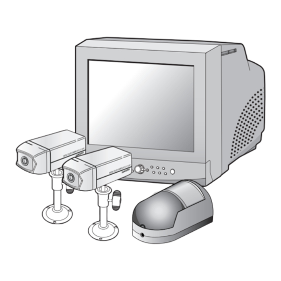
Page 13: 1-2) System Components
SENSOR INSTALLATION MANUAL CAMERA CABLE CAMERA BRACKET CONNECTOR ITEM MODEL DESCRIPTION Q’ty NOTE MONITOR SMO-150QP 15" FLAT CRT MONITOR STANDARD CAMERA SOC-C120P NORMAL TYPE CAMERA PIR CAMERA SOC-C321P PIR OBSERVATION CAMERA Tapping Screw 2 CAMERA BRACKET SBR-110 STAND TYPE BRACKET... -
Page 14: 1-3) Camera Composition And Installation Method
1-3) CAMERA composition and installation method 1) Standard Camera composition (SOC-C120P) PIN NUMBER SPEC SPEAKER(HOT) VIDEO_OUT SPEAKER(COLD) AUDIO_OUT/ALARM_OUT 12V DC a. Lens It has a focal length of 3.8mm and makes it possible for you to observe a relatively wide area. - Page 15 e. SENSOR jack Used to connect the sensor to the camera. f. Speaker It outputs the sound signal which was transfered from the monitor. • PIN configuration of the DOME CAMERA is the same as the STANDARD CAMERA. • But, DOME CAMERA does not provide ALARM JACK. 2) Installing Syandard Camera (SOC-C120P) SOC-C120P s camera can be attached to the wall, ceiling or shelf using the camera mount bracket (SBR-110).
- Page 16 3) PIR Camera composition (Top) (Bottom) ① Lens It has a focal length of 3.8mm and makes it possible for you to observe a relatively wide area. ➁ Fresnel Lens An infrared focusing lens for increasing the sensitivity of the built-in PIR sensor. English-16...
- Page 17 ➂ 6-pin modular jack Used to connect the camera to the monitor. PIN NUMBER SPEC VIDEO_OUT AUDIO_OUT/ALARM_OUT 12V DC ➃ 5-Pin Terminal Block A terminal block for supplying backup power for the PIR sensor operation during power outages and for transmitting the relay signals to external devices during the PIR sensor operation.
- Page 18 (Sensor Detection Angle & Area) 1) Vertical Detection Line Please consider the horizontal detection area and the vertical detection line when choosing • an installation site. 2) Horizontal Detection Area English-18...
- Page 19 (Inside) ⑤ Function Switch A function switch for the PIR sensor operation. Function Sensor Sensitivity On, On : Low On, Off : Normal Off, On : Normal Off, Off : High Alarm Led On/Off (Sensor On) Sensor On/Off ➅ PIR Sensor A thermal heat sensor that detects infrared radiation projected by warm objects.
- Page 20 Camera installation Hints 1. Do not install directly towards rising or setting sun. Can cause burn or damage to internal options. 2. Do not limit desired detection zone by interference of curtains, screens, potted plants, etc. 3. Also, do not locate it in front of source of water/oil vapors. Avoid placement of heat source inside detection zone.
- Page 21 4) Installing the PIR Camera (SOC-C321P) 1. Choose an installation site that can sufficiently support 5 times the weight of the equipments to be installed. 2. Remove the screw (BH M2.6) at the bottom of the main unit by turning it counterclockwise, and then lift the assy-case front as you push it upward to detach it from the case-rear.
- Page 22 4. Connect the Camera connector (RJ-11) cable to the case-rear as well as the cable to be connected to the terminal. 5. Align the two holes of the case-rear to the holes of the plastic anchors, and then fasten the screw-tappings (BH M3 X 30).
- Page 23 6. Adjust the direction of the lens. 1) Use the cross (+) screw driver to turn the screw (indicated by the arrow in the illustration) counterclockwise slightly. The lens body will move. 2) Tilt the lens body down about 10° from the horizontal, and then turn the screw clockwise to fasten it. Screw (HB M4 x L8) 7.
- Page 24 Installing the Camera using the Mount-Corner 1. Choose an installation site that can suffi ciently support 5 times the weight of the equipments to be installed. 2. Place the mount-corner to the corner to which you want to install the camera and mark screw holes with a pencil (indicated by the blue circles in the illustration).
- Page 25 4. Remove the screw (BH M2.6) at the bottom of the main unit by turning it counterclockwise, and then lift the assy-case front as you push it upward to detach it from the case-rear. (❊ Do not apply excessive force, as doing so may damage the inside assembly.❊ ) Assy-case front Screw (BH M2.6) CASE-REAR...
- Page 26 2) Passing the cables through the hole on the mount-corner. Pass the cables through the hole on the mount-corner as shown in the right picture below. 6. Assemble the case-rear onto the mount-corner by aligning the two holes of the caser-ear to the protrusions of the mount-corner (indicated by the blue circles in the illustration) and fastening the screw-tappings (PH M3 X 16).
- Page 27 7. Adjust the direction of the lens. 1) Use the cross (+) screw driver to turn the screw (indicated by the arrow in the illustration) counterclockwise slightly. The lens body will move. 2) Tilt the lens body down about 10° from the horizontal, and then turn the screw clockwise to fasten it.
- Page 28 4) Camera Mount Bracket(SBR-110) & Standard Camera (SOC-C120P) (1) Overview CAMERA MOUNT BRACKET (SBR-110) is used to attach the camera to a wall, ceiling or shelf. (2) Installation Explains the installation of CAMERA MOUNT BRACKET as wall as the installation of the camera onto the CAMERA MOUNT BRACKET.
- Page 29 • Loosen the handle by turning it in a counter clockwise direction and then adjust the camera position . Tighten the handle, turning it clockwise, and lock the camera in position. • Connect the camera cable to the camera. Handle (3) Specifications Use : Indoor Installation : Wall or Ceiling...
-
Page 30: 1-4) Camera Composition And Connecting Method To Monitor
1-4) CAMERA Composition and Connecting Method to MONITOR After positioning monitor and installing three cameras to a desired location, please connect CAMERA to MONITOR through CAMERA CABLE (MCB-60 or MCB-100) as shown in the below figure. Please check whether or not it is properly connected. Connection status checking method : •... -
Page 31: 1-5) External Terminal Connecting Method For Camera And Monitor
1-5) External terminal connecting method for CAMERA and MONITOR 1) External terminal connecting method for CAMERA • An additional PIR sensor or external sensor can also be connected. • The additional PIR sensor can be connected as shown in the above graphic. •... -
Page 32: 1-6) Whole System Connection And Configuration
f) Connect the A/O (HOT) terminal on the rear panel to the Alarm IN terminal of the VCR. g) Connect the A/O (COLD) terminal on the rear panel to the Ground terminal of the VCR. h) Connect the A/R terminal on the rear panel to the Alarm Reset terminal of the VCR. i) Connect the G (ground) terminal on the rear panel to the Ground terminal of the VCR. -
Page 33: Chapter 2: Monitor Front Panel Key Function And Using Method
Chapter 2: MONITOR FRONT PANEL KEY Function and Using Method Front Panel 2-1) TALK KEY TALK KEY allows users to transmit voice signal to intended camera by inputting voice with built-in MIC in the front of the monitor. For this function, select a target camera (CH 1, 2, 3, 4) with the œ... -
Page 34: 2-4) Power Save- Key
2-4) POWER SAVE- KEY Allows users to set POWER SAVE MODE of monitor. PICTURE screen is off when the POWER SAVE KEY is pressed, and the ON/OFF status of the monitor can be judged through LED ON/OFF status. Users can exit from POWER SAVE MODE by pressing POWER SAVE BUTTON again under picture “OFF”... -
Page 35: 2-8) Pip- Key
2-8) PIP- KEY Can be used to see the main screen while Single screen is displayed. The main screen can be changed and transfered to another channel while PIP is working. Please refer to "CHAPTER 4. DISPLAY MODE SETTING" for PIP function and details. 2-9) FREEZE- KEY This key allows users to see a target camera picture at PAUSE MODE. -
Page 36: 2-13) Enter- Key
2-13) ENTER- KEY As a multi functional œ œ ENTER√ √ key, it allows users to 1. enter SET UP MENU movement and SETTING MODE and set data, and 2. display single camera picture. Please refer to the below picture. œ... -
Page 37: Chapter 3: Setting Each Item Function At Setup Menu
Chapter 3: Setting each item function at SETUP MENU Pressing the MENU BUTTON of the FRONT PANEL allows users to enter SETUP MENU and see the following menu OSD box. Setting method of each SETUP MENU function and operation is as follows. 06/01/03 13:14:00 SETUP... -
Page 38: 3-2) Date/Time Menu Function Setting
3-2) DATE/TIME MENU Function setting • Function: Sets the display date format and current time. Setting method :Move to #2. DATE/TIME MENU by using œ œ ENTER√ √ SWITCH at setup menu, • then press the ENTER SWITCH to display the OSD as shown in the below figure. (The figure shows the initial setting status.) 06/01/03 13:14:00... -
Page 39: 3-4) Display Menu Function Setting
3-4) DISPLAY MENU function setting • Function : Allows users to select the color and ON/OFF of borderline at QUAD DISPLAY. Setting method : Move to #4. DISPLAY SETTING MENU by using œ œ ENTER√ √ SWITCH at • SETUP MENU, then press the ENTER SWITCH to display the OSD as shown in the figure below. (The figure shows the initial setting status.) 06/01/03 13:14:00... -
Page 40: 3-5) Title Menu Function Setting
3-5) TITLE MENU Function setting • Function: Set the title of each camera at your discretion. Setting method: Move to #5. TITLE MENU by using œ œ ENTER√ √ SWITCH at SETUP MENU, • and press the ENTER SWITCH to display the OSD as shown in the figure below. (The figure shows the initial setting status.) 06/01/03 13:14:00... -
Page 41: 3-6) Alarm Menu Function Setting
3-6) ALARM MENU Function setting • Function: Allows users to set the ALARM MODE for each camera. Setting method: Move to #6. ALARM MENU by using œ œ ENTER√ √ SWITCH at SETUP • MENU, and press the ENTER SWITCH to display the OSD as shown in the figure below. -
Page 42: 3-7) View Event Log Menu Function And Setting Method
3-7) VIEW EVENT LOG MENU function and setting method • Function: Displays the time and date of camera event and type of event. Setting method: Move to #7. VIEW EVENT LOG MENU by using œ œ ENTER√ √ SWITCH at •... -
Page 43: Chapter 4: Display Mode Setting Method
Chapter 4: DISPLAY MODE setting method 4-1) SINGLE SCREEN DISPLAY Initial display mode of monitor is QUAD-A. In case users want to see the camera image at full mode, select a target camera by turning œ œ ENTER√ √ SWITCH left and right. After that, press the ENTER SWITCH and selected camera image will be displayed at full screen. -
Page 44: 4-2) Quad Mode Display
4-2) QUAD MODE DISPLAY Users can switch SINGLE DISPLAY MODE and SEQUENTIAL DISPLAY MODE to QUAD DISPLAY MODE, or QUAD-A (QUAD-B) to QUAD-B (QUAD-A), or PIP MODE to QUAD MODE, press the QUAD/PAGE KEY. * At QUAD MODE display from SINGLE MODE or SEQUENCE MODE 06/01/03 13:14:00 06/01/03... -
Page 45: 4-3) Auto Sequential Display Mode
4-3) AUTO SEQUENTIAL DISPLAY MODE Pressing on the SEQUENCE KEY on the front allows screen to automatically switch to SINGLE MODE full screen or QUAD MODE. (‘no-signal’ channels will be skipped while single screen is auto-switching.) If the DWELL TIME SETTING of SETUP MENU is set to 3 seconds and the SEQUENCE KEY is pressed at this time, the operation will be carried out as follows. -
Page 46: 4-4) Pip Mode Display
4-4) PIP MODE DISPLAY Can be used to see PIP screen in Single screen mode. If you press the œ œ ENTER√ √ on PIP screen ,the main screen will change. If you press the œ œ ENTER√ √ to the left and right,the main screen can be transferred to another channel. Sub-screen location can be selected on DISPLAY MENU in SETUP MENU. -
Page 47: 4-5) Zoom Mode Display
4-5) ZOOM MODE DISPLAY When users want to see zoomed image of a specific area of the display, press the ZOOM KEY in the front to display zoom selection area. Select zoom target area by turning œ œ ENTER√ √ SWITCH left and right, and press the ENTER SWITCH, then, the selected area will be displayed at full single mode with zoomed area doubled. -
Page 48: Chapter 5: Each Product Feature
Chapter 5: Each product feature SOC-C120P : Standard Camera Model Name SOC-C120P Broadcasting System PAL STANDARD Imaging Device 1/4'' SUPER HAD IT CCD Effective Pixels 500(H) x 582(V) Synchronization Internal Resolution H : 330 TV Lines, V : 350 TV Lines Signal Output VBS 1.0Vp-p (75 ohm composite) S/N Ratio... -
Page 49: Soc-C321P : Pir Camera
SOC-C321P : PIR Camera Model Name SOC-C321P Broadcasting System PAL STANDARD Imaging Device 1/4'' SUPER HAD IT CCD 500(H) X 582(V) Effective Pixels Internal Synchronization H : 330 TV Lines, V : 350 TV Lines Resolution VBS 1.0Vp-p (75ohm composite) Signal Output ≤... -
Page 50: Observation Monitor
350 TV Lines or more (Live Mode Full Screen) Horizontal Resolution 0 °C ~ 40 °C Operation Temperature SMO-150QP : 15" FLAT CRT Dimension (W x D x H (mm)) 15" : (MONITOR) 388 X 459 X 379, (PACKING) 462 X 543 X 613 Weight 15"... - Page 51 Memo English-51...
- Page 52 Part No.: AA68- Printed in Korea...