Miele KM 391 Operating And Installation Instructions
Gas cooktop
Hide thumbs
Also See for KM 391:
- Operating instructions manual (36 pages) ,
- Specifications (7 pages) ,
- Product and cut-out dimensions (1 page)

Related Manuals for Miele KM 391


Summary of Contents for Miele KM 391
-
Page 1: Gas Cooktop
Operating and Installation Instructions Gas Cooktop KM 391 ® ® To prevent accidents and machine damage, read these instructions installation or use. M.-Nr. 06 073 600... - Page 2 ß ß ß ß ß...
- Page 3 ....... . . 4 ..........8 .
- Page 4 Please contact the To guarantee the electrical safety nearest Miele Dealer or the Miele of this appliance, continuity must Technical Service Department with exist between the appliance and an specific requirements.
- Page 5 Do not use pans that extend past the burner grate. Using larger pans Do not operate the cooktop until it may cause the flames to spread out is properly installed in the and damage the surrounding countertop. countertop or other countertop This appliance is intended for appliances.
- Page 6 Do not leave the cooktop unattended while in use. Boil-overs The burners become very hot cause smoking, and greasy spill-overs when in use. Make sure that no one may ignite. comes in contact with the burners. Do not use water on grease fires. Children should not be left alone or Smother any fire or flame, or use a unattended in an area where the...
- Page 7 Turn off the gas shut off valve, and its power cord does not come into disconnect completely from the contact with the cooktop. electrical supply. Contact the Miele Always make sure food is Technical Service Department. sufficiently cooked or reheated. If...
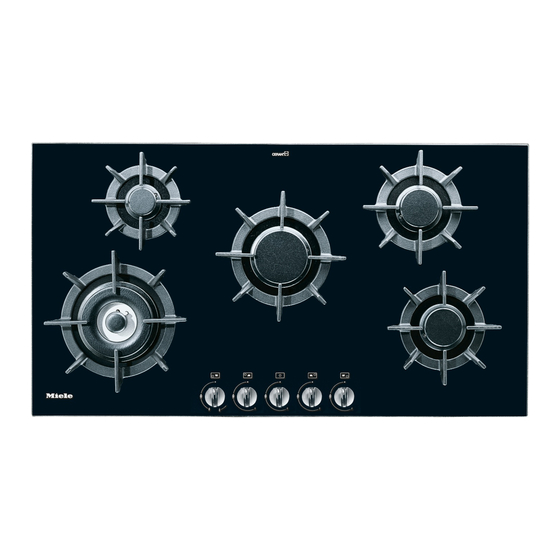
- Page 8 a Wok burner Control knobs b Auxiliary burner h Front left burner c Fast burner i Rear left burner d Normal burner j Center burner e Grates (for each burner) k Rear right burner f Burner symbols l Front right burner g Power cord...
- Page 9 m Burner cap n Burner ring o Burner head p Burner base q Ignitor r Ignition Safety control...
- Page 10 Metal components have a protective coating which may give off a slight Before using for the first time clean the smell the first time your new appliance appliance as follows: is heated. ^ The gas burner assembly can be The harmless smell and any vapors will washed in a mild solution of water dissipate after a short time and do not and liquid dish soap.
- Page 11 The gas cooktops are equipped with a Fast-Ignition-System which incorporates the following features: – The control knob can be released once it is turned to the largest flame symbol. – If the flame goes out during use, e.g. from a draft, the burner will auto- ß...
- Page 12 ^ To light a burner press down and turn The inner and outer burners are both the corresponding control knob controlled by one control knob. There is counter-clockwise to the largest a stop at the 6 o’clock position that flame symbol and release the knob. requires you to press the knob down The ignitor will click and ignite the while turning it in order to get from the...
- Page 13 – Set the cooktop to a high flame when Wok burners: using a large diameter pan and low You can use a wok on the special wok flame when using small diameter burners with out any additional rings, pans. trivets etc. –...
- Page 14 This appliance is equipped with an ignition safety control. This control cuts If there is an interruption to the the gas supply if the flame goes out electrical supply, the gas can be and re-ignition is unsuccessful. ignited using a match. ^ To re-ignite the burner, turn the ^ Press down and turn the desired control knob to "ß", then follow the...
- Page 15 Never use scouring agents or pads, ^ Let the appliance cool to a safe abrasive cleaning agents or strong temperature before removing the cleaners such as oven sprays, stain grates. or rust removers, as these could ^ Clean the grates and knobs with a damage the surface of the sponge and a mild solution of warm appliance.
- Page 16 The burner can be dismantled and cleaned when completely cool. ^ Remove the burner parts and wash them in a solution of hot water and liquid dish soap. ^ Dry them thoroughly. Make sure that the flame holes are clean and completely dry.
- Page 17 Be careful not to mix up the parts. Make sure that all the locating tabs and notches align exactly. ^ Place the burner head, o, on to the burner base, p, so that the ignitor, q, and the ignition safety control, r, extend through their respective holes in the burner head.
- Page 18 All repairs should be performed by a ^ Check whether the burners are trained technician in strict assembled correctly. accordance with national and local ^ Make sure the gas holes in the codes. Any repairs or maintenance performed by unqualified personnel burner ring are clean and open.
- Page 19 In the event of a fault which you cannot easily fix yourself, please contact the Miele Technical Service Department. U 1-800-999-1360 techserv@mieleusa.com V 1-800-565-6435 service@miele.ca When contacting Technical Service please quote the serial number and model of the cooktop. This information is visible on the silver data plate supplied with the cooktop.
- Page 21 INSTALLATION INSTRUCTIONS...
- Page 22 The minimum distances given in these Installation Instructions must be observed in order to ensure safe operation. Failure to do so increases the risk of fire. To prevent damage to the cooktop, the cabinetry and venting hood should be installed first. Gas appliances should only be installed in a well ventilated area.
- Page 23 13 these applications. Please contact the inches (330 mm). If the cabinet nearest Miele Dealer or the Miele manufacturer recommends a greater Technical Service Department with distance, follow that manufacturer’s specific requirements.
- Page 24 a Building-in depth b Mains connection box c Gas connection R - ISO 7-1 (DIN2999)
- Page 25 ^ Prepare the worktop cut-out as shown in the diagram. Remember to maintain a minimum safety distance of 2 " (70 mm) between the hob and the back wall and 6" (152 mm) between it and a side wall or tall unit to the right or left of the hob.
- Page 26 ^ Screw the gas regulator onto the nipple underneath the cooktop. (See "Gas Connection" for more guidance). ^ Feed the power cord through the cut-out to the power outlet. ^ Set the cooktop in the cut-out and center it. ^ Install the cooktop so that the power cord or gas piping does not come into contact with any portion of the ^ Secure the cooktop at the...
- Page 27 The cooktop must not be permanently sealed into the countertop when installed. The sealing strip under the edge of the cooktop provides a sufficient seal for the countertop. If the cooktop is sealed into position, the countertop or appliance may be damaged if the cooktop needs to be removed for maintenance or service.
- Page 28 This appliance must be electrically This appliance is equipped with a grounded according to local or three-prong grounding plug to national codes. prevent shock hazards. It should be All electrical work should be plugged directly into a properly performed by a qualified electrician grounded outlet.
- Page 29 Caution: Label all wires prior to disconnection when servicing controls. Wiring errors can cause improper and dangerous operation. Verify proper operation after servicing.
- Page 30 Installation and service must be The gas connection must be made performed by a qualified installer, in accordance with local codes or, in service agency or the gas supplier. the absence of local codes, with In Massachusetts a licensed the National Fuel Gas Code, plumber/gasfitter is required.
- Page 31 Do not use any regulator unless it A pressure regulator that is convertible has been supplied by Miele. Doing from natural to LP gas (Propane) or vice so may cause a gas leak. versa is included with the appliance. The adjusted pressure is for: If there is any doubt concerning natural gas - 4"...
- Page 32 Max. output 5000 1.47 Min. output 0.21 Max. output 6000 1.76 Min. output 1000 0.29 Max. output 9500 2.78 Min. output 1700 0.50 Max. output 15300 4.48 Min. output 0.19 Max. output 41800 12.25...
- Page 33 All cooktops come set for connection to either natural gas or LP gas. The ^ Unscrew the hexagonal silver cap adjustment of the included regulator located on the top of the regulator. corresponds with the gas type of the ^ Make sure that the spring stays in cooktop.
- Page 34 Turn off the main gas supply (if the appliance has already been installed) and disconnect it from the main electrical power supply before proceeding. The following orifices and needle valves should be installed into their respective burners. Auxiliary burner 1.05 0.44 Normal burner 1.15...
- Page 35 ^ Remove the pan support, the burner cap, a, and the burner head, b. ^ Using a 7 mm nut driver or socket, unscrew the orifice, c. ^ Install the new orifice and reassemble the above parts in the reverse order. ^ Take off the burner cap, a, burner ring, b, and burner head, c.
- Page 36 To change the needle valves, the burner securing screws must first be loosened and the upper section of the appliance removed. ^ Remove the operating controls by pulling them upwards. ^ Remove the upper section. ^ Take off the ignition switch, a. ^ Loosen the needle valves, b, (smaller diameter) and the (larger diameter) , c, with a screwdriver.
- Page 37 or when the control knob is quickly turned from "high" to low ^ After converting the cooktop unit to the flame should not go out. another type of gas, affix the label supplied with the conversion kit next the gas flame must to the data plate underneath the burn with the center clearly visible.
- Page 38 The cardboard box and packing Old appliances contain materials that materials are biodegradable and can be recycled. Please contact your recyclable. Please recycle. local recycling authority about the possibility of recycling these materials. Before discarding an old appliance, disconnect it from the gas and electrical supply and cut off the power cord to prevent it from becoming a hazard.
- Page 40 Alterations rights reserved / 0804 M.-Nr. 06 073 600 / 00 This paper consists of cellulose which has been bleached without the use of chlorine.