Advertisement
Available languages
Available languages
Quick Links
Download this manual
See also:
Use and Care Manual
iNSTALLATiON
AND SERVICE MUST BE PERFORMED BY A QUALiFiED
iNSTALLER.
iMPORTANT:
SAVE FOR LOCAL ELECTRICAL iNSPECTOR'S USE.
READ AND SAVE THESE iNSTRUCTiONS
FOR FUTURE REFERENCE.
_r_
If the information
in this manual
is not followed
exactly,
a fire or explosion
may result
causing
property
damage,
personal
injury or death.
FOR YOUR SAFETY:
--
Do not store
or use gasoline
or other
flammable
vapors
and liquids
in
the vicinity
of this or any other
appliance.
--
WHAT
TO DO IF YOU
SMELL GAS:
•
Do not try to light
any appliance.
•
Do not touch
any electrical
switch;
do not use any phone
in your
building.
•
Immediately
call your
gas supplier
from
a neighbor's
phone.
Follow
the gas supplier's
instructions.
•
If you
cannot
reach your
gas supplier,
call the fire department.
--
Installation
and service
must
be performed
by a qualified
installer,
service
agency
or the gas supplier.
30" Min. *
(76.2 cm)
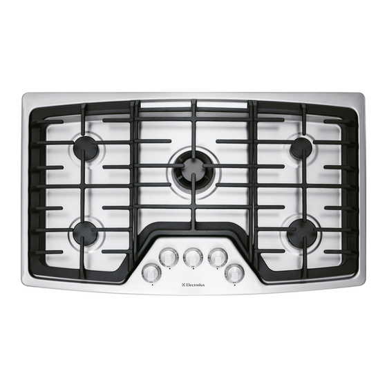
Gas Cooktop
Dimensions
C
Gas Cooktop
Cutout Dimensions
Figure I
All dimensions are stated in inches and (cm).
DimensionH includes a 5" (12.7 cm) spaceunderneath the cooktop for connection to gas supply line.
NOTE: Wiring diagrams
for this cooktop
are enclosed in this booklet
Printed in United States
318201472
(0812)
Rev. E
English - pages 1-9
Espahol-
p_iginas 10-17
Frangais - pages 18-26
Wiring Diagram 27-28
Advertisement

Related Manuals for Electrolux EW30GC60IS2


Summary of Contents for Electrolux EW30GC60IS2
- Page 1 iNSTALLATiON AND SERVICE MUST BE PERFORMED BY A QUALiFiED iNSTALLER. iMPORTANT: SAVE FOR LOCAL ELECTRICAL iNSPECTOR'S USE. READ AND SAVE THESE iNSTRUCTiONS FOR FUTURE REFERENCE. If the information in this manual is not followed exactly, a fire or explosion may result causing property damage,...
- Page 2 important Notes to the Installer • Be sure your cooktop is installed and grounded Read all instructions contained in these installation properly by a qualified installer or service technician. instructions before installing the cooktop. Remove all packing material before connecting the •...
- Page 3 13"(33cm) Max.Depth ForCabinet 30" (76.2 cm) Installed A bove Min. Clearance Cooktop. Between the Top of the Cooking Platform and Unprotected Wood or Metal B Minimum Distance Between Clearance Cabinet Rear Edge of Cutout and Nearest Combustible Surface Above 18"Min. Countertop.
- Page 4 Counter Installation of an Electric Built-in Typical Under Oven with a Cooktop Mounted Above Side filler panels are necessary to iso- All mounting hardware must be late the unit from adjoining cabinets. used to secure the built-in oven to This cooktop may Panel height should allow for installa- the cabinets.
- Page 5 Typical Gas Cooktop Installation Over Electric Built-in Oven Installed Under the Counter A__ I_l----- 18" (45.7 cm) Max.-----_ ÷ 4" (10.2 cm) Manifold Pi 120V/6OHz Flexible Connector Grounded Right Side of Flare Outlet Cabinet Union Wall Oven Cabinet Pressure Regulator Cabinet sides or filler panel Manual Shutoff Valve...
- Page 6 Wall Outlet Location To clamp down, insert an angle bracket into the slot on each side of the unit as shown. Run thumb screw up through the bracket, up against the bottom of the 12,, --_ counter. Tighten until the unit draws down and is secure. Provide an Adequate Gas Supply...
- Page 7 Once regulator is in place, open the shutoff valve in the Install Pressure Regulator gas supply line. Wait a few minutes for gas to move Install the pressure regulator with the arrow on the through the gas line. regulator pointing up toward the unit in a position where you can reach the access cap.
- Page 8 Do not, underanycircumstances, cut or removethe Check Operation third (ground)prongfrom the power cord, Refer to the Use and Care Guide packaged with the cooktop for operating instructions and for care and Disconnect electrical supply cordfrom cleaning of your cooktop. wallreceptacle b efore servicing cooktop. Do not touch the burners.
- Page 9 Turn on Electrical Power and Open Main Shutoff Gas Valve Clockwise Check the Igniters Operation of electric igniters should be checked after cooktop and supply line connectors have been Counterdo_ carefully checked for leaks and the cooktop has been connected to electric power. To operate the surface burner: Push in and turn a surface burner knob to the...
- Page 10 LA INSTALACION Y EL SEP,VICIO DEBEN SEP, P,EAUZADOS POP, UN INSTALADOP, CAUFICADO. IMPOP,TANTE: GUAP,DE ESTAS INSTP,UCCIONES PAP,A USO DEL INSPECTOR ELECTP,ICO LOCAL. LEA Y GUAP,DE ESTAS INSTP,UCCIONES PAP,A FUTUP,AS P,EFEP,ENCIAS Si todas las instrucdones de este manual no son observadas a la letra, se puede ocurrir...
-
Page 11: Instrucciones De Seguridad Importantes
No deje articulos que interesan los ni_os en los Notas importantes para el instalador: 1. Lea todas las instrucciones de instalaciOn antes de armarios que est_n sobre la la plancha de cocinar. realizar la instalaci6n de la plancha de cocinar. Les podria causar quemaduras graves si intentan 2. - Page 12 M_ix. profundidad degabinetes instalados por encima d ela 30" (76.2cm) plancha d e Minimo de empotar e s13" (33cm). espacio e ntre laparte B Minimo Distancia entreel superio dela Esoacio borde posterior delhueco y la plataforma d e mas cerca superficie combustible laplancha d e porencima delmostrador.
- Page 13 Tipica instalaci6n de un horno el ctrico empotrado con una plancha de cocinar por encima Entrepafios Ilenador de lados son necesarios para aislar el aparato de los armarios adyacentes. La altura de panel debe de permitir la instalaci6n de Todas las fijaciones de modelos de planchas de cocinar montaje deben de estar aprobantes.
- Page 14 Instalaci6n tipica de la plancha de cocinar a gas pot encima de un homo electrico empotrado instalado debajo del mostrador 18" (45.7 cm) M_ix.-----_ ÷ 4" (10.2cm) 61/2" Tubo mOIti 5" (13.5 cm) (12.7 cm) Min. UniOn Lado derecho UniOn del armario 120V/6OHz Conector...
- Page 15 Para hacer la conversi6n del gas natural al gas propano, es Instalaci6n de ia piancha de coccinar necesario utilizar el servicio de un t@cnico calificado, in 1, Examine visualmente la plancha de cocinar para saber acuerdo con las instrucciones del fabricante y todos los si hay daho, c6digos y reglamentos reguladores.
- Page 16 de tres patas (a tierra) que calza con un enchufe de pared de tres patas de conexi6n a tierra (ver Figura 9) para disminuir la posibilidad de peligro de choques el_ctricos desde el artefacto. Un electricista calificado debe verificar el enchufe de pared y el circuito para asegurar que el enchufe est_q conectado a tierra correctamente.
- Page 17 todaslascintas delasbases d elos 5. Ajuste bajo "LOW" para la valvula de quemador quemadores yverifique queestos de superficie puente o triple (Figura 11) (algunos seencuentren acomodados Tapa del modelos) Nota: En la wqlvula de quemador triple el correctamente sobre labase del quemadore ajuste <<LOW>>...
- Page 18 UN INSTALLATEUR QUALIFII_ DOlT EFFECTUERL'INSTALLATION ET LE SERVICE iMPORTANT: CONSERVEZCES iNSTRUCTiONS POUR LES INSPECTEURSLOCAUX. LISEZ CESiNSTRUCTiONS ET CONSERVEZ-LESPOUR Ri_FI_RENCES ULTI_RIEURES. Si les instructions de ce manuel ne sont pas suivies a la lettre, il pourrait en resulter un incendie ou une explosion susceptible de causer des dommages materiels, des blessures ou m_me la mort.
- Page 19 • Assurez-vous que votre appareil est correctement Notes importantes a I'lnstallateur 1. Lisez toutes les instructions contenues dans ce feuillet install6 et mis _ la terre par un installateur ou un technicien d'entretien qualifi& avant d'installer I'appareil. • Le circuit 61ectrique de cette plaque de cuisson 2.
- Page 20 Pour_liminer l esrisques d ebr01ures ou defeu enallongeant le brasau-dessus des surfaces d ecuisson chaudes, _vitezd'installer d esarmoires au-dessus delaplaque decuisson. Sivousdevez eninstaller, il estpossible d er_duire lerisque enplacant u nehottepourcuisini_re q uiexc_de horizontalement d'unminimum de5" (12.7cm)labase deI'armoire. D_gagement minimum de30" (76.2cm)entrele hautdelasurface decuisson e t la...
- Page 21 Des panneaux lat_raux d es_paration doivent _treinsta%s p ourisoler I 'appareil Les attaches a nti-versements doivent _ treutilis_es desarmoires a ccol_es. Lahauteur d es pourretenirlefourencastr_ a uxarmoires. panneaux doitpermettre I 'installation des modules detables decuisson a pprouv_es. Reportez-vous auxinformations typiques Cette tabledecuisson p eut-_tre i nsta%e a udessus d e d'unetabledecuisson _ gazinsta%e a u- certains m odules defours encastr_s _lectriques.
- Page 22 4" (_0.2cm) 5" Max. 6 1/2" M in. Murde droite de Prise d e Tube enm_tal f lexible I'armoire 120V/6OHz Manchon conduit d'alimentation engaz mise _ laterre _vas_ R_gulateur de pression MurdeI'armoire g auche _ -'_" oumurdes_paration Robinet d'arr_t m anuel (l'acc_s aurobinet d 'arr_t Armoire doit_trefacile)
- Page 23 Si vous d_sirez convertir votre plaque de cuisson au gaz 9010 peut #tre command# en passant par votre centre de propane, servez-vous des orifices _ d_bit fixe qui sont service ou en t_l_phonant au 1-877-ELECTROLUX (1-877- fournis et emball_s dans un sac marqu_ "POUR 435-3287).
- Page 24 Important: Enlevez tout I'emballage e t la Le tuyau d'alimentation dolt _tre @quip@ d'un robinet documentation dela plaque decuisson a vant d e d'arr_t approuv@. Ce robinet devrait _tre situ@dans la brancher le gazet lecourant_lectrique s urcelle-ci. m@mepi@ceque la plaque de cuisson et _ un endroit permettant de I'ouvrir et de le fermer sans difficult@.
- Page 25 Branchez le courant electrique a la plaque de cuisson au gaz Alirnentation en electricite Circuit de d_rivation de 120 volt, 60 Hertz, avec mise la terre appropri_e, prot_g_ par un disjoncteur de 1 5 Emplacement de la amperes ou un fusible temporis_. N'utilisez pas de - plaque signal_tique rallonge...
- Page 26 2. Branchez ['alimentationen _[ectricit_et ouvrez[e d. Enlevez le bouton de commande et r_glez le robinet robinet principald'a[imentationen gaz. comme indiqu_ _ I'_tape e. e. La dimension de la flamme de la portion artiste ou 3.V_rifiez[esa[[umeurs exteme du brQleur peut _tre augment_e ou diminu_e IIfautv_rifier l efonctionnement desallumeurs en toumant la vis A.
- Page 27 • _ 0swocd ,LOW_ > wD© __°£N£d © < w©c_ cc©_ ©- -©m mw-C_ P-'9 _o--w ..os_(o uJ i _<J © r,4_ o--< ..mwWm 0sLJ sss_s ° LZPw_-_ _uoz < CDC_D < _z[n _oZ_° . ZLU> _<ow -©zc_z 0D_-- D'----L--O _LUm...
- Page 28 > r3 _ w©o £ • £ o> ©D 0f o w© o< © r?< @<-- w c_ o o rT? '" o _ 3 o \ s \ o WW • >D (,,, _) 3• © o > • o ©...