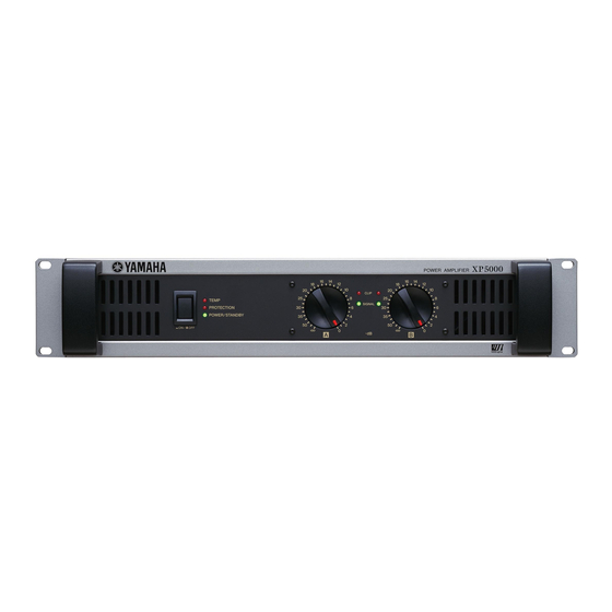
Yamaha XP7000 Owner's Manual
Xp series power amplifier
Hide thumbs
Also See for XP7000:
- Service manual (92 pages) ,
- Owner's manual (20 pages) ,
- Manual de instrucciones (20 pages)
Summary of Contents for Yamaha XP7000
-
Page 1: Power Amplifier
POWER AMPLIFIER OWNER’S MANUAL BEDIENUNGSANLEITUNG MODE D’EMPLOI MANUAL DE INSTRUCCIONES... -
Page 2: Explanation Of Graphical Symbols
1. IMPORTANT NOTICE: DO NOT MODIFY THIS UNIT! This product, when installed as indicated in the instructions contained in this manual, meets FCC requirements. Modifications not expressly approved by Yamaha may void your authority, granted by the FCC, to use the product. 2. IMPORTANT: When connecting this product to accessories and/or another product use only high quality shielded cables. - Page 3 • Do not open the device or attempt to disassemble the internal parts or modify inspected by qualified Yamaha service personnel. them in any way. The device contains no user-serviceable parts. If it should appear to be malfunctioning, discontinue use immediately and have it inspected by qualified Yamaha service personnel.
- Page 4 Yamaha service personnel. Yamaha cannot be held responsible for damage caused by improper use or modifications to the device, or data that is lost or destroyed. Always turn the power off when the device is not in use.
-
Page 5: Table Of Contents
Thank you for purchasing a Yamaha XP7000, XP5000, XP3500, XP2500, XP1000 Series Power Ampli- fier. The XP Series of power amplifiers was developed from Yamaha’s wealth of experience in building PA equipment and its tradition of careful attention to every detail of circuit design. These power amplifiers feature high power —... -
Page 6: Controls And Functions
If a DC voltage is detected at the amplifier’s outputs XP7000/5000: Power shut down and the indicator is not lit. XP3500/2500/1000: The protection system is active. Once the DC voltage problem is corrected, the protec-... -
Page 7: Rear Panel
If you are having a problem with hum or noise, use this • 26dB: Setting of 26dB terminal to connect to ground (earth) or to connect to • 32dB: Setting of 32dB the chassis of a mixer, preamp, or other device in your system. XP7000/XP5000/XP3500/XP2500/XP1000 Owner’s Manual... -
Page 8: Speaker Connections
Note: In this case, the loads for A and B are connected directly in the amplifier. Make sure not to input any signal to the B terminal. ● 5-way binding post ● Speakon connector – – 4Ω* 4Ω* 4Ω* 4Ω* * Minimum speaker * Minimum speaker impedance impedance XP7000/XP5000/XP3500/XP2500/XP1000 Owner’s Manual... -
Page 9: Bridged Mode
Note: In this case, the loads for A and B are directly connected in the amplifier. Make sure not to input any signal to the B terminal. ● 5-way binding post ● Speakon connector – Minimum speaker Minimum speaker impedance: 8Ω impedance: 8Ω XP7000/XP5000/XP3500/XP2500/XP1000 Owner’s Manual... -
Page 10: High-Impedance Speaker Connections
High-impedance speaker connections (XP7000/3500 only) The XP7000 enables you to connect in stereo or parallel fashion multiple high-impedance speakers that support 70V line output. The number of speakers that can be connected varies depending on the speaker’s rated input. You can connect speakers with a total rated input per channel of up to 625 W. -
Page 11: Connection
BRIDGE 2 Insert the Neutrik NL4FC plugs into the Speakon con- nector on the rear of the amplifier, and turn clockwise to lock. 1– A– 1– Neutrik NL4FC plugs – 2– B– 2– ı CHANNEL 1– B– XP7000/XP5000/XP3500/XP2500/XP1000 Owner’s Manual... -
Page 12: Troubleshooting
A DC voltage of +2 V/-2 V or The relay operates to PROTECTION indica- Consult your dealer or the near- greater was generated in the protect the speaker sys- tor lights. est Yamaha service center. power amplifier’s output circuit. tem. ● XP7000, XP5000 Indicator(s) Possible Cause Remedy... -
Page 13: Specifications
20mS nonclip 500 W 500 W 500 W SN Ratio 20 Hz-20 kHz (DIN AUDIO) 96 dB Power Standby / idle 5 W / 20 W Consumption 1/8 (4 Ω/Pink noise) 170 W 170 W 170 W XP7000/XP5000/XP3500/XP2500/XP1000 Owner’s Manual... - Page 14 Yamaha Corp. reserves the right to change or modify products or specifica- tions at any time without prior notice. Since specifications, equipment or options may not be the same in every locale, please check with your Yamaha dealer. XP7000/XP5000/XP3500/XP2500/XP1000 Owner’s Manual...
-
Page 15: Monitor/Remote Pin Layout
STANDBY STANDBY Control: Supply 5 VDC, 5 mADC MONITOR MODEL ID XP7000: 1.0 kΩ, XP5000: 1.2 kΩ, XP3500: 1.5 kΩ, XP2500: 1.8 kΩ, XP1000: 2.2 kΩ (Impedance to GND) REMOTE CONTROL MUTE CH B MUTE On Control: Connect the pin to GND (max. 1mA flows) -
Page 16: Block Diagram
■ Block Diagram ● XP7000/XP5000 XP7000/XP5000/XP3500/XP2500/XP1000 Owner’s Manual... - Page 17 ● XP3500/XP2500/XP1000 XP7000/XP5000/XP3500/XP2500/XP1000 Owner’s Manual...
-
Page 18: Current Draw
Test signal: Pink Noise, bandwidth limited from 22Hz to 22kHz 1W = 0.860kcal/h, 1BTU = 0.252kcal Note that Line Voltage [V] x Line Current [A] = [VA], not equals to [W]. Inrush current XP7000, XP5000: 11A (100V), 13A (120V), 25A (240V) XP3500: 11A (100V), 13A (120V), 22A (240V) XP2500:... - Page 19 Memo XP7000/XP5000/XP3500/XP2500/XP1000 Owner’s Manual...
- Page 20 Memo XP7000/XP5000/XP3500/XP2500/XP1000 Owner’s Manual...
- Page 22 Yamaha Pro Audio global web site: http://www.yamahaproaudio.com/ Yamaha Manual Library: http://www.yamaha.co.jp/manual/ C.S.G., Pro Audio Division © 2005 Yamaha Corporation 305POAPx.x-01E0 Printed in Vietnam WF37200...


