
Related Manuals for GE 70R-1000D


Summary of Contents for GE 70R-1000D
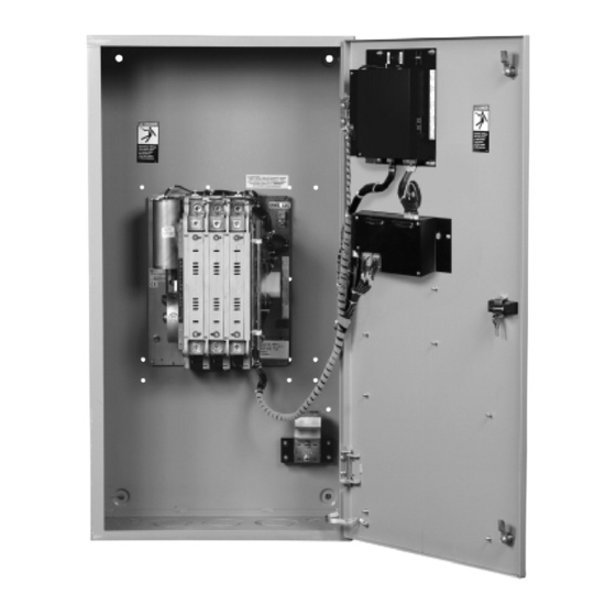
- Page 1 70R-1000D 11/04 GE Zenith Controls Series Transfer Switches ZTGD 40-3000 Amps Operation and Maintenance Manual...
-
Page 2: Table Of Contents
Introduction GE Zenith Transfer Switches are used to provide a continuous source of power for lighting and other critical loads by auto- matically transferring from source 1 power to source 2 power in the event that source 1 voltage falls below preset limits. -
Page 3: Safety
Safety / Installation (Can Cause Severe Injury or Death) Turn OFF all power before installation, adjustment, or removal of transfer switch or any of its components. The safe operation of your switch is GE Zenith’s focus. The proper storage, installation, operation and mainte- nance will help increase the life of the switch. -
Page 4: Power Connections
Installation (cont’d) (Can Cause Severe Injury or Death) Turn OFF all power before installation, adjustment, or removal of transfer switch or any of its components. Power Connections GE Zenith transfer switches are supplied with UL listed solderless screw type terminals as standard for the Source 1, Source 2 and Load power connections. -
Page 5: Control Connections
Installation (cont’d) (Can Cause Severe Injury or Death) Turn OFF all power before installation, adjustment, or removal of transfer switch or any of its components. Control Connections Figure 2 Engine Start Connections Input/Output Connectors to I/O Modules A complete information package is furnished with... -
Page 6: Initial Energization
Installation (cont’d) (Can Cause Severe Injury or Death) Turn OFF all power before installation, adjustment, or removal of transfer switch or any of its components. Figure 3 Engine Start Control Connections The engine-start terminals are clearly identified by a label on the microcontroller backplate. In the case of... - Page 7 Source 1 Voltage is above the preset restore value. The Gen-Set will start and run while Source 2 stop Delay Timer is timing. GE Zenith Controls ZTG/ZTGD Operation and Maintenance Manual (70 Close the External (up-stream) Source 2 line circuit breaker.
-
Page 8: Mx150 Microprocessor Controller
S 1 O K 2 1 : 5 6 M O N 2 3 A P R 2 0 0 2 M O R E T E S T MX150 Figure 7 -1000D) MX150 Board Battery Strip Access Code Label GE Zenith Controls... -
Page 9: Lcd & Keypad
The word above the key changes depending on which screen is being displayed. GE Zenith Controls ZTG/ZTGD Operation and Maintenance Manual (70 no changes can be made without entry of the access code. The factory set six-digit access code is located on a white label on the back of the unit (see figure 9 pgs. -
Page 10: User Setting For Voltage & Frequency
Once satisfied, the W timer will begin timing to transfer to Source 2. Standard Features, MSTDG Option Pkg. Test Switch, Momentary Auxiliary Contact: Closed when the switch is in Source 2 position. Auxiliary Contact: Closed when the switch is in Source 1 position. - Page 11 Source 2 position. This assumes that the outage will be an isolated event. When this Feature is set to ON: The transfer Switch is committed to transfer to Source 2 position once the W timer has begun timing, even if Source 1 power returns before the transfer to Source 2.
-
Page 12: Standard Features, Mexeg Option Pkg
In addition to the features listed under the MSTDG Option Package, this enhanced package includes the following features: Additional Auxiliary contact: closed when switch is in Source 2 position. Additional Auxiliary contact: Closed when the transfer switch is in Source 1 position. -
Page 13: Optional Accessories
Manual Transfer Switch transfers in either direction by depressing designated pushbuttons. Digital Power Meter with Display: Amps, Volts, and Frequency. GE Zenith Controls ZTG/ZTGD Operation and Maintenance Manual (70 Digital Meter w/Display of Amps, Watts, Volts, Frequency, KVA, KVAR, PF, etc. -
Page 14: How To Set The System Clock
19. Cursor is indicated as a line under character to be changed. Change values with up and down keys. 20. Press SAVE when complete. 21. Press MORE repeatedly until SET USER SETUP then press BACK then ESC to the S1 OK screen. -1000D) GE Zenith Controls... - Page 15 No-Load Exerciser Or allow the controller to complete retransfer to Source 1 If the CDT Exerciser is Factory configured for a Load Exerciser GE Zenith Controls ZTG/ZTGD Operation and Maintenance Manual (70 (cont’d) How to Bypass the next exercise event and Keep...
-
Page 16: Cdp Clock Exerciser
To save value and to To previous field move cursor to next or to exit screen. field to be changed. -1000D) Load No-Load (CDP) Exercise Indicator Exercise duration for this event in hours and minutes up to 10 hours per event GE Zenith Controls... -
Page 17: User Setup - Cfg Menu
Customer Input Voltage PROG 1 PROG 2 GRD (Input Sink) Controller Outputs have "Limited" Source Capacity. NIA OUT Use only GE Zenith-specified Output Modules. ELEV. PRE. OUT ALARM OUT MOTOR DISC. OUT Output Contacts INHIB.>S1 INHIB.>S2 R1 Output Contact Rating: 10A @ 250 VAC or 30 VDC... -
Page 18: User Setup - Set Menu
Customer Input Voltage PROG 1 PROG 2 GRD (Input Sink) Controller Outputs have "Limited" Source Capacity. NIA OUT Use only GE Zenith-specified Output Modules. ELEV. PRE. OUT ALARM OUT MOTOR DISC. OUT Output Contacts INHIB.>S1 INHIB.>S2 R1 Output Contact Rating: 10A @ 250 VAC or 30 VDC... -
Page 19: User Setup - System Info
Customer Input Voltage PROG 1 PROG 2 GRD (Input Sink) Controller Outputs have "Limited" Source Capacity. NIA OUT Use only GE Zenith-specified Output Modules. ELEV. PRE. OUT ALARM OUT MOTOR DISC. OUT Output Contacts INHIB.>S1 INHIB.>S2 R1 Output Contact Rating: 10A @ 250 VAC or 30 VDC... -
Page 20: Testing
Testing A periodic test of the transfer switch under load conditions is recommended to insure proper operation. (See National Electric Code articles 700 and 701) ATS Testing Start generator and verify proper voltage, frequency and phase sequence (match to Source 1). Shut down gen set and place in Auto. -
Page 21: Sequence Of Operation
MX controller initiates a transfer signal through the SCR-E to operate the main transfer operator. The load is now transferred to Source 2 line. The transfer switch is mechanically locked. SN limit switch awaits the next operation to Source 1. Restoration of Source 1 Power: When Source 1 power reach the preset "Restore"... -
Page 22: Controls Power Supply (Cps)
Primary Voltage Assembly Board Part No. 120V 50P-1224 50P-1200 208-220V 50P-1225 50P-1201 230-240V 50P-1226 50P-1202 277V 50P-1227 50P-1203 380-400V 50P-1228 50P-1204 416-440V 50P-1229 50P-1205 460-480V 50P-1230 50P-1206 575-600V 50P-1231 50P-1207 -1000D) GE Zenith Controls... - Page 23 Controls Power Supply (CPS) Standard Transition CPS Schematic C.V. SCR-N Delayed Transition CPS Schematic C.V. C.V. SCR-N SCR-EO GE Zenith Controls ZTG/ZTGD Operation and Maintenance Manual (70 C.V. SCR-E C.V. C.V. SCR-E SCR-NO (cont’d) XN1 - SOURCE 1 CONTROL TRANSFORMER...
-
Page 24: Troubleshooting & Diagnostics
Troubleshooting and Diagnostics HAZARDOUS VOLTAGES CAN CAUSE SEVERE INJURY OR DEATH. These charts may indicate problems that require authorized GE Zenith service personnel. Hazardous voltages may exist on termination plugs other than those that go into the MX150. General Troubleshooting The following troubleshooting guide is used to recognize, and determine basic faults. -
Page 25: Maintenance And Testing
Should debris contaminate the mechanism, clean and apply additional Lubriplate. GE Zenith can provide complete preventative main- tenance services. Please contact the GE Zenith Technical Services Department for additional information. GE Zenith Controls ZTG/ZTGD Operation and Maintenance Manual (70... -
Page 26: Power Panel & Replacement Parts
Power Panel and Replacement Parts Standard Transition - 40 to 260 Amps Solenoid Type SCR-N SCR-E CN/CE SCN/SCE ZTG/ZTGD Operation and Maintenance Manual (70 -1000D) GE Zenith Controls... - Page 27 Power Panel and Replacement Parts Standard Transition - 400 to 600 Amps Molded Type GE Zenith Controls ZTG/ZTGD Operation and Maintenance Manual (70 CN/CE -1000D) (cont’d) N1 N2 N3 NN SCR-N SCR-E...
-
Page 28: Amps
(Qty 1) 23P-1327 (Qty 2) 23P-1328 (Qty 3) 23P-1334 (Qty 4) 23P-1336 (Qty 1) 23P-1333 (Qty 2) 23P-1334 (Qty 3) 23P-1328 (Qty 4) 23P-1330 Operator L-4009; Operator L-4009; Contact Block L-1020 Contact Block L-1020 PS-8896 -1000D) (cont’d) ARC GRID SCR-N SCR-E MOVABLE CONTACT GE Zenith Controls... - Page 29 Main Operating Coils 575/600 CCN Cutout Switch CCE Cutout Switch Emergency Position Auxiliary Contact Normal Position Auxiliary Contact Disconnect Switch (older versions) SCR-N, SCR-E GE Zenith Controls ZTG/ZTGD Operation and Maintenance Manual (70 SCR-N SCR-E MOVEABLE CONTACT Recommended as Spares 1600...
-
Page 30: Delayed Transition
Coil Volts MAIN K-2245B 208/240 K-2246B 380/415 K-2247B 440/480 K-2248B 575/600 K-2249B 575/600 K-2249B -1000D) (cont’d) 600 Amps 100-400 S-2591 S-1393F #4-600 MCM #2-600 MCM SECONDARY 58P-1106 58P-1107 58P-1108 58P-1109 58P-1110 58P-1110 E3054 L-3078 L-3078 E-3521 PS-8895 GE Zenith Controls... - Page 31 Delayed Transition - 800 to 1200 Amps TERMINAL BLOCKS SN1, 2, 3, 4 TERMINAL BLOCKS SE1, 2, 3, 4 STATIONARY CONTACT SCR-N/SCR-E SCR-NO/SCR-EO GE Zenith Controls ZTG/ZTGD Operation and Maintenance Manual (70 (cont’d) SCR-N ARC GRID SCR-NO SCR-EO MOVABLE CONTACT SCR-E PS-8896...
- Page 32 23P-1171 23P-1171 23P-1400 23P-1344 See Chart Below PS-8896 Solenoid Part No. S.P.O. S.P.O. K-2151 K-2151 K-2151 K-2151 K-2151 K-2151 K-2160 K-2160 S.P.O. S.P.O. K-2160 K-2160 K-2151 K-2151 Consult Factory 23P-1540 23P-1540 23P-1541 23P-1541 23P-1542 23P-1542 23P-1543 23P-1543 GE Zenith Controls...
- Page 33 GE Zenith Controls ZTG/ZTGD Operation and Maintenance Manual (70 -1000D)
- Page 34 ZTG/ZTGD Operation and Maintenance Manual (70 -1000D) GE Zenith Controls...
- Page 35 GE Zenith Controls ZTG/ZTGD Operation and Maintenance Manual (70 -1000D)
- Page 36 Zenith Controls A Product of GE Industrial Systems General Electric Company 830 West 40 Street, Chicago, IL 60609 USA 773 299-6600 , Fax: 773 247-7805 www.geindustrial.com...