Table of Contents
Advertisement
Quick Links
Advertisement
Table of Contents

Related Manuals for Yamaha CRW2200S Series


Summary of Contents for Yamaha CRW2200S Series
- Page 1 OWNER’S MANUAL...
- Page 2 Otherwise, there is an increased risk of electrical shock, fire, or damage to the device. Return the device immediately to the store where it was purchased, or alternatively, to the nearest Yamaha dealer (listed at the back of this manual).
- Page 3 Yamaha dealer (listed at the back of this manual). The device should be serviced about once a year. This drive is for use only with movable equipment, weighing less than 18 kg.
- Page 4 2. All trademarks contained in this manual belong to their respective owners. 3. Yamaha does not bear any responsibility for any outcome as a result of using this device. 4. Reproduction of this manual, either in part or in full, is expressly forbidden.
-
Page 5: Table Of Contents
This document may not, in whole or in part, be copied, photocopied, reproduced, translated, transmitted, or reduced to any electronic medium of machine readable form without prior consent in writing from Yamaha. Windows is a registered trademark of Microsoft Corporation. -
Page 6: Scsi Connection And E-Ide (Atapi) Connection
– Power cable • The included SCSI convertor is for the CRW2200 drive only. Do not use it with any other device. YAMAHA and its suppliers do not guarantee operation if it is used with any other device. For IDE Connection “E-IDE (ATAPI) Connection Set Up”... -
Page 7: Introduction
This technology reduces phase interference of the laser beam, so that it projects accurately onto the disc. Jitter value, an important measure of recording quality, has been improved 25% compared with Yamaha models not using this technology. Running OPC (Optimum Power Control) Running OPC automatically adjusts the output of the laser according to the characteristics of the disc being used. - Page 8 A Buffer Underrun Error will permanently ruin the disc. Yamaha Buffer Underrun Protection Buffer Underrun Protection is featured in Yamaha’s CRW2200 series CD-R/ RW drives. When a buffer underrun is about to occur, a buffer underrun error is prevented by temporarily suspending the writing process. Writing resumes when enough data has accumulated again in buffer memory.
-
Page 9: Before Use
Before Use System Requirements In order to use the CRW2200 drive, your computer system will need to meet the following requirements. Note The CRW2200 drive may not write at the maximum speed depending on your computer’s system configuration. PC/AT-Compatible Computer CPU: Pentium II-class or higher, 300MHz or faster. -
Page 10: Supported Discs
• Refer to the page at the URL below before attempting to read these discs on a Yamaha CD-R/RW drive not bearing the High Speed CD-RW logo. URL: http://www.yamaha.co.jp/english/product/computer/ *1 Compatible with Orange Book Part 2. - Page 11 Before Use About CD-ROMs A CD-ROM disc is a compact disc containing high-density read-only data. It has many applications, including the playback of music and video, the archiving of data, as well as on-line documentation. The following are descriptions of each CD-ROM format: CD-DA: Up to 79 minutes of stereo audio is written in 16-bit resolution at a sampling rate of 44.1kHz for a 79 minute disc.
- Page 12 Before Use About 10X-speed writing/rewriting of a High Speed CD-RW disc 10X-speed writing/rewriting of a High Speed CD-RW disc is enabled with the CLV method, and the 4X-10X Full CAV method. Commonly, writing/rewriting is enabled with the CLV method. When writing/rewriting with packet writing, you can also select the Full CAV method.
-
Page 13: Serial Number
Before Use Serial Number Once you have taken the CRW2200 drive out of its packaging, you should immediately note down the serial number found at the top of the drive with the bar code. You may need to refer to this number when requesting Customer Support services. -
Page 14: Front And Rear Of Unit
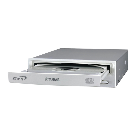
Front and Rear of Unit Front Panel Disc tray The tray is used to hold the disc. It slides out from the drive unit when a disc needs to be loaded or unloaded. ( P. 50) Manual Eject hole Only use this if no other method is available for unloading a disc. ( P. 51) Eject button Press this button when you need to open or close the tray. -
Page 15: Rear Panel (With The Scsi Convertor)
Front and Rear of Unit Rear Panel (with the SCSI Convertor) Jumper switch Plug a plastic shunt into this jumper switch to set up SCSI ID, Parity, Terminator and Block Size. ( P. 20 – 23) SCSI INTERFACE connector Insert the connector of the SCSI ribbon cable here. ( P. 26, 33) DC IN connector (The SCSI convertor’s side) Insert the smaller connector of the power cable (included). -
Page 16: Rear Panel (Without The Scsi Convertor)
Front and Rear of Unit Rear Panel (without the SCSI Convertor) DIGITAL AUDIO OUT connector If your sound card has a SPDIF (digital audio) input connector, you can connect the DIGITAL AUDIO OUT connector of the unit to the SPDIF connector using a digital audio cable (sold separately). -
Page 17: Scsi Connection Set Up
SCSI Connection Set Up Make sure that the SCSI card to connect to the CRW2200S is installed beforehand. ( P. 4) Tools Phillips Screwdriver You will need to use this when removing the cover of your computer and when mounting the drive. You may also need to temporarily remove the sound card to gain access to the CD audio connectors, in which case, a small screw retaining the sound card’s face plate has to be removed. -
Page 18: Crw2200S Setup Flowchart
SCSI Connection Set Up CRW2200S Setup Flowchart For easy cross-referencing, the relevant pages in this manual are given. Connecting the CRW2200S STEP ( P. 14 – 29) 1. Opening the Computer ( P. 14) 2. Audio cable connection ( P. 16) 3. -
Page 19: Connecting The Crw2200S
SCSI Connection Set Up Connecting the CRW2200S This section explains how to connect the CRW2200S by SCSI to a tower-type computer. Note The way of removing the casing or panel, or installing built-in devices may differ from your computer. Be sure to follow the procedures in the documentation that came with your computer. Opening the Computer 1 1 1 1 Shut down your computer and unplug it from the AC outlet. - Page 20 SCSI Connection Set Up 3 3 3 3 Touch a metal part of the computer’s chassis or power supply unit to discharge any static electricity from your body. Or, wear an anti-static grounding wrist strap. You can permanently damage your Discharge any static charge equipment if you touch it with static electricity in your body.
- Page 21 • If you use the CRW2200S as a supplemental drive for the unit, and the CD-ROM drive or DVD-ROM drive is already connected to the sound card, YAMAHA recommends you playback audio CDs using the existing drive.
- Page 22 SCSI Connection Set Up Connecting the digital audio cable The digital connection for the CRW2200S is ideal for pure quality audio playback, outputting digital signals recorded on CDs to the sound card without any distortion. Examples of the digital connection To output digital audio signals to external devices, you must use the digital connection to connect the unit and the sound card.
- Page 23 SCSI Connection Set Up Installing the SCSI Convertor to the CRW2200 drive Notes • Do not touch the connector pins or the circuit board. Otherwise, it may cause a malfunction with the SCSI convertor. • Please follow the instructions below. Do not use excessive force when installing. Otherwise, it may cause damage.
- Page 24 SCSI Connection Set Up 7 7 7 7 Connect the forked end of the power cable (included) to the drive’s and the SCSI convertor’s DC INPUT connectors. Connect the smaller connector to the SCSI convertor with the yellow wire to the left.
- Page 25 SCSI Connection Set Up Setting the Jumper Switches 8 8 8 8 Before fitting the CRW2200S into the computer, you need to set up the drive using the jumper switches located at the rear of the unit. You’ll need to set the following: SCSI ID number Parity check Termination...
-
Page 26: Scsi Id Number
SCSI Connection Set Up SCSI ID Number Each of the SCSI devices connected to the computer is identified by its SCSI ID number. You need to assign a number from “0” to “7” for each SCSI device. Commonly, ID number “7” is reserved for the computer’s SCSI card itself. Therefore, the CRW2200S can actually be assigned an ID number from “0”... - Page 27 SCSI Connection Set Up Parity Check The parity check is used for error correction during data transmissions. If parity- checking has to be disabled, the shunt on the Parity jumper switch should be removed. Parity ON (Default) Parity OFF Normally leave this setting alone.
-
Page 28: Block Size
SCSI Connection Set Up Termination ON (Default) Termination OFF ID SELECT ID SELECT PARITY PARITY TERMINATOR TERMINATOR BLOCK SIZE BLOCK SIZE Set to "OFF" if the CRW2200S Set to “ON” if CRW2200S is is not the last device on the last device on SCSI chain SCSI chain Note... - Page 29 SCSI Connection Set Up Choosing the Connection Method 9 9 9 9 The CRW2200S can be used as an supplemental drive or as a replacement drive. As a supplemental drive If the casing of your computer has a spare 5.25-inch drive bay available, such as with many tower-type computers, you can install the CRW2200S supplemental to the computer’s existing CD-ROM drive.
- Page 30 SCSI Connection Set Up Installing the CRW2200S 10 10 10 10 As a supplemental drive Remove the front cover of a vacant 5.25-inch drive bay slot. 5.25-inch drive bay slot Front cover Note To remove the front cover, refer to the documentation that came with your computer. As a replacement drive Disconnect all the cables connected to the rear of the existing CD-ROM drive, and also disconnect the audio cable from the sound card or motherboard’s audio...
- Page 31 SCSI Connection Set Up The following explains how to add the drive to the computer as illustrated. If you are replacing the existing CD-ROM drive, the procedure is basically the same. Note The way of installing built-in devices may differ, depending on the computer. Refer also to the documentation that came with your computer.
- Page 32 SCSI Connection Set Up 13 13 13 13 Connect the audio cable to the sound card. Connecting the analog audio cable There are two connectors at the sound card side of the cable: a vertically-mounted type (PH) and a horizontally-mounted type (MPC). Audio cable Choose the one that matches your sound card’s connector and leave the...
- Page 33 SCSI Connection Set Up 14 14 14 14 Connect the 4-pin power cable from the computer’s power supply to the power cable from the CRW2200S. Bottom Power cable 4-pin power cable Bottom Notes • There may be more than one 4-pin power cable available. Any one may be used. •...
- Page 34 SCSI Connection Set Up 16 16 16 16 Attach the outer casing and all cables and peripheral devices of the computer and any screws that were removed. Cover Front panel 17 17 17 17 Reconnect the computer to the AC outlet and turn it on. When you turn on the computer, make sure the LED on the panel of the CRW2200S blinks in green, which indicates that it is reading disc information.
-
Page 35: Configuring For The Operating System
SCSI Connection Set Up Configuring for the Operating System 18 18 18 18 After the computer’s operating system (Windows 95/98/98 Second Edition/Me) has loaded, open “Control Panel” and double-click on the “System” icon. Select the “Device Manager” tab and double-click on “CDROM.”... - Page 36 SCSI Connection Set Up 19 19 19 19 Double-click on “YAMAHA CRW2200S” listed under “CDROM” (in Windows 95/98/98 Second Edition/Me) and click on the “Settings” tab. Check the “Sync data transfer” checkbox. With “Sync data transfer” enabled, the data transfer between your CRW2200S drive and your computer is synchronized, meaning that the maximum possible data transfer rate can be achieved.
-
Page 37: Removing The Scsi Convertor
Removing the SCSI convertor Tools Phillips Screwdriver You will need to use this when removing the cover of your computer and when removing the SCSI convertor from the drive. You may also need to temporarily remove the sound card to gain access to the CD audio connectors, in which case, a small screw retaining the sound card’s face plate has to be removed. - Page 38 Removing the SCSI convertor 4 4 4 4 Disconnect all cables connected to the CRW2200S and remove it from the computer. If the audio cable is connected to the CRW2200S, disconnect the sound card’s side connector only. Audio cable 50-pin SCSI flat cable 4-pin power cable 5 5 5 5 Remove the screw securing the SCSI convertor to the CRW2200 drive.
- Page 39 Removing the SCSI convertor 6 6 6 6 Remove the SCSI convertor from the CRW2200 drive. SCSI convertor 7 7 7 7 Disconnect the power cable from the SCSI convertor and the CRW2200 drive. The smaller connector connected to the SCSI convertor is locked with its hook. Lift up the connector to unlock the hook, then pull it out.
-
Page 40: E-Ide (Atapi) Connection Set Up
E-IDE (ATAPI) Connection Set Up If the CRW2200S has already been installed to the computer by SCSI connection, remove it from the computer and detach the SCSI convertor. ( P. 32 – 34) Tools Phillips Screwdriver You will need to use this when removing the cover of your computer and when mounting the drive. -
Page 41: Crw2200E Setup Flowchart
E-IDE (ATAPI) Connection Set Up CRW2200E Setup Flowchart For easy cross-referencing, the relevant pages in this manual are given. STEP Does your computer have a SCSI Remove the SCSI connection with the drive? convertor. ( P. 32 – 34) Connecting the CRW2200E STEP ( P. -
Page 42: Connecting The Crw2200E
E-IDE (ATAPI) Connection Set Up Connecting the CRW2200E This section describes how to connect the CRW2200E by E-IDE (ATAPI) to a tower type computer. In this description, about some parts that is duplicated with the part of “Connecting the CRW2200S” in “SCSI Connection Set Up” ( P. 14 31), see the reference page –... - Page 43 E-IDE (ATAPI) Connection Set Up Choosing the Connection Method 4 4 4 4 First, check how existing IDE devices are connected to your computer, and then determine how to connect the CRW2200E in conjunction with those devices. As a supplemental drive If the casing of your computer has a spare 5.25-inch drive bay available, such as CRW2200E supplemental to with many tower-type designs, you can install the...
- Page 44 E-IDE (ATAPI) Connection Set Up About IDE IDE (Enhanced IDE/E-IDE) is one of the standards applied to the connection between personal computers and their peripherals. A computer motherboard provides two IDE connectors (primary and secondary). (Although, some motherboards provide only a primary connector.) You may connect up to two IDE devices (hard disk, CD-ROM, or CD-R drives) to the connectors using an IDE cable.
- Page 45 IDE cable IDE cable (primary) (secondary) To make the best use of the performance of the CRW2200E, Yamaha recommends you connect it as a sole secondary master. Note The CRW2200E is shipped with the SLAVE setting. Reset to MASTER if you...
- Page 46 • When the operating system starts with the SCSI hard drive, a primary IDE connector may have no IDE devices. In such a case, Yamaha recommends you connect the CRW2200E as a primary master.
- Page 47 E-IDE (ATAPI) Connection Set Up Setting the Jumper Switches 5 Set the CRW2200E as MASTER or SLAVE to meet your computer environment by plugging the included plastic shunt into the appropriate jumper switch on the rear panel of the CRW2200E. Rear Panel Master Slave (factory setting)
- Page 48 E-IDE (ATAPI) Connection Set Up Installing the CRW2200E 6 6 6 6 As an supplemental drive: Remove the front cover of a vacant 5.25-inch drive bay slot of the computer in case of using the CRW2200E. ( P. 25 step 10) As a replacement drive: Remove the device such as CD-ROM from the computer for CRW2200E.
- Page 49 • If you use the CRW2200E as a supplemental drive for the unit, and the CD-ROM drive or DVD-ROM drive is already connected to the sound card, YAMAHA recommends you playback audio CDs using the existing drive.
- Page 50 E-IDE (ATAPI) Connection Set Up Note Some sound cards may have one or more audio input connectors. However, depending on your connectors, the specifications may differ from the CRW2200E. If no sound is audible from the speaker even though the audio cable is connected, refer to the documentation that came with your sound card for more details, and make sure that your audio cable is connected correctly.
- Page 51 E-IDE (ATAPI) Connection Set Up 10 10 10 10 Connect a 4-pin power cable to the power supply connector of the CRW2200E marked “DC INPUT.” DC INPUT connector Bottom 4-pin power cable Notes • There may be more than one 4-pin power cable available. Any one may be used. •...
- Page 52 E-IDE (ATAPI) Connection Set Up Configuring for the Operating System 14 14 14 14 When using Windows 95/98/98 Second Edition/Me, after the computer’s operating system has loaded, open “Control Panel” and double-click on the “System” icon. Select the “Device Manager” tab and double-click on “CDROM.”...
- Page 53 15 When using Windows 95/98/98 Second Edition/Me, follow Step 14 14 14 14 to open the “Device Manager” window, then double-click on the “YAMAHA CRW2200E” icon to open the “YAMAHA CRW2200E Properties” window, and click on the “Settings” tab to select it. A screen similar to the one below appears.
- Page 54 E-IDE (ATAPI) Connection Set Up About DMA DMA (Direct Memory Access) is a method that transfers data between various peripheral devices (e.g., a hard drive, CD-R/RW drive, etc.) and the computer’s memory without using the CPU. By checking the “DMA” check box, the transmission speed of data will become high-speed.
-
Page 55: Operation
Operation You can load and eject a disc (as described below) only when the computer is turned Loading a Disc 1 1 1 1 Open the tray by pressing the Eject button on the CRW2200 drive’s front panel. 2 2 2 2 Place the disc onto the tray with its label or printing facing upward. 3 3 3 3 Close the disc tray by pressing the Eject button again. -
Page 56: Ejecting A Disc In An Emergency
Operation Notes • The disc tray will not open if the computer is not turned on. With the CRW2200 drive turned on, pressing the Eject button will not open the disc tray if ATAPI commands prohibit ejecting a disc, such as during data reading. •... -
Page 57: Troubleshooting
Troubleshooting Please refer also to the YAMAHA CD-R/RW Drive’s web site for more information. YAMAHA CD-R/RW Drives web site URL: http://www.yamaha.co.jp/english/product/computer/ Europe: http://www.yamaha-it.de/ The drive does not turn on. (When the LED on the front panel of the CRW2200 drive does not light up.) - Page 58 Troubleshooting Are you using the correct SCSI driver (mini-port driver)? If the SCSI card has not been installed correctly under Windows 95/98/98 Second Edition/Me/NT/2000 Professional, make sure that you have installed the most recent SCSI driver supplied by the SCSI card manufacturer. For information about the latest version of driver, please contact the respective SCSI card manufacturer.
- Page 59 Troubleshooting Check to see if there are any problems with other IDE devices. Some problems may occur in a multiple-IDE device system due to incompatibilities between the IDE devices and the computer, device drivers, data transfer speed, or other reasons. Make sure that the CRW2200E is recognized by the computer by temporarily removing other IDE devices from the system.
- Page 60 E-IDE (ATAPI) models, please give the CRW2200E name to the CRW2200S. 1 The “Properties” setting of the CRW2200S. Open the “YAMAHA CRW2200S Properties” window and click on the “Properties” tab. Uncheck the “Enable digital CD audio for this CD-ROM device.” check box.
- Page 61 CDs, CD-ROMs, and blank CD-R/RW discs (the front panel LED remains lit in orange after a disc is inserted), you should contact your nearest Yamaha dealer. The “Buffer Underrun” error message is displayed. If your CD writing software supports the Buffer Underrun Protection, you must activate the Buffer Underrun Protection.
-
Page 62: Appendix
Appendix Writing Modes Disc-at-Once (DAO) This mode is used when writing a complete disc in a single pass without pausing. Data cannot be added later, even if the full capacity of the blank disc has not been used. Example: General CD-ROM Data Track 1 Any remaining space... -
Page 63: Packet Writing
Appendix Session-at-Once (SAO) As a writing method that combines the advantages of the above-mentioned “Disc-at- Once” and “Track-at-Once,” you can combine multiple tracks into one session and write them, and then add additional data. For example, this is the writing method used to create a CD EXTRA format CD. The music tracks will be recorded in the first session, and the data will be recorded in the second session. -
Page 64: About Firmware
To ensure more reliable operations and enhanced performance of the drive, updates to the firmware will be made available. You can find information about the most recent firmware for the drive on YAMAHA CD-R/RW Drive’s web site. URL for YAMAHA CD-R/RW Drives web sites: http://www.yamaha.co.jp/english/product/computer/... -
Page 65: Led Indicator Messages
Appendix LED Indicator Messages The CRW2200 drive properly installed inside the computer will indicate the following LED messages while the drive (and the computer) are turned on. Status Indicator Messages LED Color Ready (with disc) Green Ready (no disc) Orange Tray operation (opening/closing) Blinking (constant) Green... - Page 66 Appendix Writing Methods Disc-at-Once (DAO) Session-at-Once (SAO) Track-at-Once (TAO) Packet Writing Writing/Reading Speed Writing CD-R 1X, 2X, 4X, 8X, 12X (CLV), 16X (12X – 16X Partial CAV) 20X (12X – 20X Partial CAV) CD-RW 2X, 4X, 8X, 10X (CLV) 4X – 10X Full CAV Reading 40X (max.) Full CAV Note) •...
- Page 67 Appendix Average Random Access Time 150 msec. (reading) Sector Size 2,048 – 2,352 bytes Interface SCSI connection • SCSI-3 Fast 20 (Ultra SCSI) E-IDE (ATAPI) connection • Enhanced IDE (E-IDE)/ATAPI Installing style Horizontal Disc Loading Type Front auto-loading tray loading Audio Out Analog audio output Frequency range: 20 –...
- Page 68 Appendix The CRW2200 series complies with the following specifications Compliance Specifications Country / Region Details Category Item Standards Safety Electrical UL60950 Information Technology Equipment Laser 21CFR1040.10 Class 1 Laser Product FDA Chapter 1, Subchapter J Emission 47CFR15 Class B Computing Device FCC Part 15, Subpart B Canada Safety...
-
Page 69: Index
Appendix Index Symbols 40-pin IDE cable ......25, 43 Eject button ........9, 50 4-pin power cable....25, 28, 33, 46 Ejecting a Disc ........50 5.25-inch drive bay slot......25 Ejecting a Disc in an Emergency ..51 50-pin SCSI flat cable....26, 33 Extraction of digital audio data.... - Page 70 Appendix Packet ........... 58 Packet Writing ........58 Paper clip ..........51 Parity check.......... 22 Partial CAV..........6 Phillips Screwdriver....12, 32, 35 Plastic shunt ........20, 42 Power cable ........19, 34 Primary..........39 Properties ....30, 31, 47, 48, 55, 59 Pure-Phase Laser System .......