Table of Contents
Advertisement
Available languages
Available languages
Owner's
Manual
icR. M..i
AiR COMPRESSOR
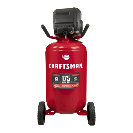
33-gallon
1.7 HP
Oil-Free,
UMC
Model
No. 921.165720
CAUTION:
Before using this product, read this
manual and follow all its Safety
Rules and Operating instructions.
• Safety instructions
• Installation & Operation
• Maintenance
& Storage
• Troubleshooting
Guide
• Parts List
• EspaSol,
p. 24
Sears Brand Management
Corporation,
Hoffman
Estates,
IL 60179
U.S.A.
www.sears.com/craftsman
04/12/2013
Part No. E106178
Advertisement
Table of Contents

Related Manuals for Craftsman 921.165720


Summary of Contents for Craftsman 921.165720
- Page 1 Owner's Manual icR. M..i AiR COMPRESSOR 33-gallon 1.7 HP Oil-Free, Model No. 921.165720 CAUTION: • Safety instructions • Installation & Operation Before using this product, read this • Maintenance & Storage manual and follow all its Safety Rules and Operating instructions.
-
Page 2: Table Of Contents
Spanish ..........Service Number ........back cover ONE YEAR FULL WARRANTY ON CRAFTSMAN AIR COMPRESSOR If this Craftsman Air Compressor fails due to manufacturer's defects in material or workmanship within one year of the date of purchase, RETURN IT TO THE NEAREST SEARS STORE OR SERVICE CENTER IN THE UNITED STATES and it will be replaced or repaired (at our option), free of charge. - Page 3 This manual contains information that is important for you to know and understand. This information relates to protecting YOUR SAFETY PREVENTING EQUIPMENT PROBLEMS. To help you recognize this information, we use the symbols below. Please read the manual and pay attention to these symbols. Indicates a potentially Indicates an imminently hazardous situation which, if not...
- Page 4 Restricting any of the com- • Never place objects against pressor ventilation openings or on top of compressor. will cause serious overheat- • Operate compressor in an open ing and could cause fire. area at least 12" (30.5 cm) away from any wall or obstruction that would restrict the flow of fresh air to the ventilation openings.
- Page 5 IR_r_ RISK OF BURSTING Air Tank: On February 26, 2002, the U.S. Consumer Product Safety Commission published Release # 02-108 concerning air compressor tank safety: Air compressor receiver tanks do not have an infinite life. Tank life is dependent upon several factors, some of which include operating conditions, ambient condi- tions, proper installations, field modifications, and the level of maintenance.
- Page 6 RiSK OF ELECTRICAL SHOCK WHAT CAN HAPPEN HOW TO PREVENT iT Your compressor is powered by • Never operate the compressor electricity. Like any other electrically outdoors when it is raining or in wet conditions. powered device, if it is not used properly it may cause electric shock.
- Page 7 RiSK OF HOT SURFACES WHAT CAN HAPPEN HOW TO PREVENT iT • Touching exposed metal such Never touch any exposed metal as the compresSor head, engine parts on compressor during or head, engine exhaust or outlet immediately after operation. tubes, can result in serious burns. Compressor wi!l remain hot for several minutes after Operation.
- Page 8 RiSK OF UNSAFE OPERATION WHAT CAN HAPPEN HOW TO PREVENT iT • Unsafe operation of your • Review and understand all compressor could lead to serious instructions and warnings injury or death to you or others, in this manual. • Become familiar with the operation and controls of the air compressor.
-
Page 9: Glossary
Always wear Certified safety of use; noise from this Pr0duct equipment: ANSI S12:6 may contribute to hearing loss: (S3.19) hearing protection. SAVE THESE INSTRUCTIONS FOR FUTURE USE Model No. 921.165720 Running Horsepower 1.7 * Bore 2.875" (73.025 mm) Stroke 1.45" (36.83 mm) Voltage... -
Page 10: Duty Cycle
compressor pump. Pump Produces the compressed air with a NPT (National Pipe Thread) reciprocating piston contained within the A seal thread tape must be used to cylinder. provide a leak-free seal on pipe threaded connections. Regulator Pressure Gauge Displays the current line pressure. Line Pressure Regulator Knob pressure is adjusted by rotating the Regulates the outgoing pressure from... - Page 11 I Power Switch Air Intake Filter Rf _ q a rri rp_q rfcnrru cprmrt c NpTt_)cqajc _rmrfcnskn knTrrp Ibjqmrf casrg - k sqr_u vtq" c i cnr d;cc rrdbc" I:_J1, asr-_rsr nl:cqqspc qcrrdl Af cai rri b gw" q_q rrp" cdrpc c af sqc, I_$1qu_af qc_cq...
-
Page 12: Assembly
ASSEMBLING THE COMPRESSOR The air compressor should be turned off, unplugged from the power source, the air bled from the tank and the unit allowed time to cool before any maintenance is performed. Personal injuries could occur from moving parts, electrical sources, compressed air or hot surfaces. -
Page 13: Installation
GETTING STARTED Location of the Air Compressor The air compressor should always be located in a clean, dry and well ventilated environment. The unit should have at minimum, 12 inches of space on each side. The air filter intake should be free of any debris or obstructions. Check the air filter on a daily basis to make sure it is clean and in working order. - Page 14 GETTING STARTED Extension Cords Use only a 3-wire extension cord that has a 3-blade grounding plug, and a 3-slot receptacle that will accept the plug on the product. Make sure your extension cord is in good condition. When using an extension cord, be sure to use one heavy enough to carry the current your product will draw.
- Page 15 DAILY STARTUP (Figure4) Set the Power Switch to the Off position. (A) inspect the air compressor, air hose, and any accessories/tools being used for damage or obstruction, if any of these mentioned items are in need of repair/ replacement, contact your local authorized dealer before use. Close the drain valve.
-
Page 16: Maintenance
To avoid personal injury, always shut off and unplug the compressor and relieve all air pressure from the system before performing any service on the air compressor. To ensure efficient operation longer life of the Before each use items to Check/Change compressor unit, routine... - Page 17 Risk of Unsafe Operation. Unit cycles automatically when power is on. When servicing, you may be exposed to voltage sources, com- pressed air, or moving parts. Before servicing unit unplug or disconnect elec- trical supply to the air compressor, bleed tank of pressure, and allow the air compressor to cool.
- Page 18 PROBLEM CAUSE CORRECTION This is normal Regulated If pressure drops too low, adjust pressure regulator while accessow is used. gauge reading Compressor not Check air requirement of accessory. drops when large enough If it is higher than CFM and pressure air accessow supplied by compressor, you need a is being used...
- Page 19 PUMP/MOTOR ASSEMBLY ® REF, NO PART NO. DFSCRJPTJON E106663 Pulley E106664 Belt E106665 E106666 Screw E106667 Flywheel E106668 Screw E106669 Screw E106670 Valve Plate Kit E106671 Conrod E106672 Head 19- ENG...
- Page 20 921.165720 • --oJ 20- ENG...
- Page 21 REE NO PART NO. DESCRIPTION E106660 SCREW E106612 MANIFOLD E106613 COVER MANIFOLD SEARS E106614 ASSY FASTENER E106615 OUTLET TUBE E106616 TANK PTD E106617 HANDLE ASSEMBLY, E106618 CHECK VALVE E106657 WASHER "14 E106619 FRONT SHROUD E106620 REAR SHROUD E106621 SAFETY VALVE E106622 ISOLATOR "18...
- Page 22 M..i COIVIPRESOR DE AiRE 125 litros 1.7 HP Sin aceite, UiVIC iVlodelo No °. 921.165720 PRECAUCION: • Instrucciones de seguridad • Instalaci6n y modo de empleo Antes de utilizar este producto, • Mantenimiento lea este manual y siga las reglas...
- Page 23 DE AIRE CRAFTSMAN Si este compresor de aire Craftsman Ilega a fallar debido a un defecto de mano de obra o de materiales en un plazo de un a_o, desde la fecha de compra, DEVUI_LVALO A LA TIENDA O AL CENTRO DE SERVlCIO SEARS MAS CERCANO EN EE.UU.
- Page 24 Este manual contiene informaci6n que es importante que usted conozca comprenda. Esta informaci6n se relaciona con la protecci6n de SU SEGURIDAD Y LA PREVENCION DE PROBLEMAS A SU EQUIPO. Para ayudarle a reconocer esta informaci6n, usamos los simbolos indicados mas abajo. Sirvase leer el manual y }restar atenci6n a estas secciones.
- Page 25 Rbestringir cualquiera de las Nunca coloque objetos con- erturas de ventilaci6n del tra o sobre el compresor. compresor puede producir un ® Opere el compresor en un lugar abierto con una dJstancia de al sobrecalentamiento grave y podria provocar un incendio. menos 30,5 cm (12 pulg.) a cual- quiet pared u obstruccidn que pud- iera restringir el fiujo de aire fresco...
- Page 26 EXPLOSION Tanque de aire: El 26 de febrero de 2002, la Comisi6n de Seguridad para Productos de Consumo delos Estados Unidos public6 el Comunicado # 02-108 sobre la seguridad en los tanques de compresores de aire: Los tanques receptores de los compresores de aire no tienen una vida Qtil infinita.
- Page 27 Neum_icos: o El inflado excesivo de los neumAti- o Utilice un medidor de presi6n cos podria causar lesiones de neumAticos para controlar graves y dafio a la propiedad. la presi6n de 6stos antes de cada uso y mlentras los infla; observe el flanco para vet la presi6n correcta del neum_.tico.
- Page 28 _1___ RIESGO DE OBJETOS DESPEDIDOS COMO EVITARLO &QUE PUEDE SUCEDER? La corriente de aire comprimido Utilice siempre equipo de puede provocar lesiones en los tejidos seguridad certificado: anteojos blandos de la piel expuesta y puede de seguridad ANSI Z87.1 (CAN/ impulsarsuciedad, astillas, part{culas CSA Z94.3) con protecci6n sueltas y objetos peque_os a gran...
- Page 29 RIESGO P OR PIEZAS M6VlLES &QUE PUEDE SUCEDER? COMO EVlTARLO • Las piezas m6viles como la polea, • Nunca haga funcionar el compresor el volante y la correa pueden pro- sin los protectores o cubiertas o vocar lesiones graves si entran en si los mismos est&n dafiados.
- Page 30 RIESGO D E CAiDAS COMO EVlTARLO &QUE PUEDE SUCEDER? • Un compresor p0rt_ti! se puede e Opere siempre e! compres0r en Caer de una mesa, banco o techo, una p0sici6n estable y segur a Para provocando dafi0s al c0mPreS0 r ev!tar que la unidad se mueva y puede producir !esiones graves accidentaimentel...
- Page 31 CONSERVE ESTAS INSTRUCCIONES PARA FUTURAS CONSULTAS Modelo N° 921.165720 Potencia de trabajo 1,7" Di&metro interior 73,.025 mm (2,875 pulg.) Carrera 36,83 mm (1,45 pulg.) Voltaje manof&sica- corriente Circuito minimo requerido Acci6n retardada Tipo de fusible Capacidad de aire en el tanque...
- Page 32 PCEPM (Pies cubicos estandar PSi (Libras pot pulgada cuadrada) Son las unidades de medida de la minuto) La unidad de medida de suministro presi6n ejercida por la fuerza del aire. de aire. La presi6n real en PSi es medida por el man6metro del compresor.
- Page 33 de alimentaci6n FHtro de entrada de abe Ant rp_cj q s.k @ _lrpncji arp_m_ g:cj_n_n "rrk" Qsk@gqrp krrrrrlowr k"@ Ijrrqisqrcq bc nl:c bc" c cqrpjg pc bc npcq_l bc Iqol osc wnlacq_l qsa_b b, Pct qcjmb&p:&k cl rc m nkb ,Cqrc @ rclq:snrrrloq_ carrk rn I rcq bc ab nrrqg_l bc srrml acl b_mw...
- Page 34 MONTAJE DEL COMPRESOR Antes de darle cualquier tipo de mantenimiento, debe apagar y desenchufar compresor de aire de la fuente de alimentaci6n electrica, adem&s debe purgar el aire del tanque y darle suficiente tiempo para enfriarse. Existe el riesgo de que las partes m6viles, las fuentes electricas, el aire comprimido...
- Page 35 PRIMER PASO: Ubicaci6n del compresor del aire El compresor del aire siempre debe de estar en un medio ambiente limpio, seco y bien ventilado. La unidad debe de tener por Io menos 30 cm de espacio libre en cada lado. La entrada del filtro de aire debe de estar limpia y sin ningQn tipo de obstrucci6n.
- Page 36 PRIMER PASO: Cables de e×tensi6n S61o utilice un cable de extensi6n de 3 alambres con una clavija para hacer tierra de 3 terminales que pueda enchufarse en un tomacorriente de 3 orificios. AsegQrese de que su cable de extensi6n est6 en buenas condiciones. Si utiliza un cable de extensi6n, compruebe que sea de la capacidad...
- Page 37 PROCEDiMIENTO DIARIO DE ARRANQUE (Figura4) Ponga el interruptor de alimentaci6n (on/off) en posici6n de apagado (off) Verifique que el compresor de aire, la manguera de aire y todas herramientas / accesorios utilizados, no tengan dafios ni obstrucciones. algunas de las piezas descritas requieren una reparaci6n o reemplazo, Ilame a su tienda local autorizada de servicio, antes de usarlo.
- Page 38 PROCEDIMIENTO DE APAGADO (Figura 4) Gire el interruptor de alimentaci6n en posici6n apagado (Off) Desenchufe el cable de la alimentaci6n del tomacorriente. Ponga en cero el regulador de presi6n de salida. (E) Quite todas las herramientas o accesorios de aire. Abra la v&lvula de drenaje para permitir que el aire del tanque se escape.
- Page 39 VERIFICACION DE LA VALVULA DE SEGURIDAD (Figura 5) Verifique la v&lvula de seguridad haciendo los tres siguientes pasos: 1. Enchufe el compresor y d6jelo funcionando hasta que alcance la presi6n de parada. 2. Lleve gafas de seguridad, jale el anillo de la v&lvula de seguridad para aflojar la presi6n del tanque.
- Page 40 El desarrollo de reparaciones puede exponer a sitios con corriente viva, partes en movimiento o fuentes de aire comprimido podrfan ocasionar lesiones personales. Antes de intentar reparaci6n alguna, desenchufe el compresor de aire y purgue toda la presi6n de aire del tanque. PROBLEMA CAUSA CORRECCI6N...
- Page 41 PROBLEMA CAUSA CORRECClON Lav&lvula de La presi6ndel tanque Reemplaceel conmutador aliviode presi6n excedi6 la presi6n activado por presi6n. se abre. normalde operaci6n. El conmutador activado por presi6nse ator6. El motor no El motor arrancar_autom_ticamente La presi6ndel tanque funciona. excede el limite cuando la presi6ndel tanque preestabiecidodel disminuya hasta un valor menor...
- Page 42 ENSAMBLAJE BOMBA/MOTOR ® NO ° REF NO ° PIEZA DESCRIPCIQN CANT E106663 Polea E106664 Correa E106665 Ventilador E106666 Tornillo E106667 Volante E106668 Tornillo E106669 Tornillo E106670 Kit de placa de v&lvula E106671 Kit de biela E106672 Cabeza 44- SP...
- Page 43 921.165720 • --oJ 45- SP...
- Page 44 NO ° REF NO°PIEZA DESCRIPCION CANT E106660 Tornillo E106612 Colector E106613 Tapa de colector Sears E106614 Sujetador de ensamble E106615 Tubo de salida E106616 Tanque, pintado E106617 Ensamble de mango, pintado E106618 V&lvula de retencidn E106657 Arandela "14 E106619 Caja delantera E106620 Caja trasera E106621...
- Page 45 Your Home For expert troubleshooting and home solutions advice: www.managemyhome.com For repair - in your home - of all major brand appliances, lawn and garden equipment, or heating and cooling systems, no matter who made it, no matter who sold it ! For the replacement parts, accessories owner's manuals that you need to do-it-yourself.