
Related Manuals for Honeywell HercuLine 2000 Series


Summary of Contents for Honeywell HercuLine 2000 Series
- Page 1 ® HercuLine 2000 Series Actuator Installation, Operation and Maintenance Manual Doc. No.: 62-86-25-10 Revision: Date: 7/08 Honeywell Field Solutions...
- Page 2 However, we assume no responsibility for its use. While we provide application assistance personally, through our literature and the Honeywell web site, it is up to the customer to determine the suitability of the product in the application.
- Page 3 HercuLink™ User Manual 62-86-25-11 HART Communications Installation and Operations Manual 62-86-25-12 Contacts World Wide Web The following lists Honeywell’s World Wide Web sites that will be of interest to our customers. Honeywell Organization WWW Address (URL) Corporate http://www.honeywell.com Honeywell Process Solutions http://www.honeywell.com/ps...
- Page 4 Symbol Definitions The following table lists those symbols that may be used in this document to denote certain conditions. Symbol Definition This DANGER symbol indicates an imminently hazardous situation, which, if not avoided, will result in death or serious injury. This WARNING symbol indicates a potentially hazardous situation, which, if not avoided, could result in death or serious injury.
-
Page 5: Table Of Contents
Contents Contents Introduction ..................... 1 Product Description ......................1 Specifications ..................5 Technical and Operating Specifications ...............5 Model Selection Guide ....................10 Installation ..................... 12 Installation Overview ....................12 Mechanical Stops .......................12 Before Starting......................13 Actuator Mounting ......................13 Mechanical Installation ....................15 Electrical Installation....................17 Burner Control/Flame Safety..............23 ®... - Page 6 Contents Lock Set Up Group .....................53 Read Status Set Up Group..................55 Drive Set Up Group ....................56 Maintenance Set Up Group..................59 Regions of Motor Travel .....................62 CAL POSOUT Group ....................63 Auto - Manual Drive Switch ..................64 Calibration ........................65 Setting End-of-Travel Limit Switches .................78 Setting Auxiliary Switches ..................81 Start-Up/Operation ................
- Page 7 Contents Tables Table 1 Specifications - General..........................5 Table 2 Recommended Minimum Wire Size......................17 ® Table 3 Terminal Connections: HercuLine 2000....................18 ® Table 4 Terminal Connections: HercuLine 2001/2002 with auto/manual............19 Table 5 Split Range Set Up Procedure .........................26 Table 6 Keypad Description ..........................32 Table 7 Set Up Tips ..............................33 Table 8 Set Up Groups ............................34 Table 9 Set Up Procedure Using Display and Keypad ..................36...
- Page 8 Contents Figures ® Figure 1 HercuLine 2000 Series Actuator ® Figure 2 HercuLine 2002 Actuator Internal View ® Figure 3 Outline and Dimensions of HercuLine 2000 Series Actuators Figure 4 Constant Torque Linkage Figure 5 Variable Torque Linkage Figure 6 Standard crank arm Figure 7 Crank arm with optional ball joint and push rod ®...
-
Page 9: Introduction
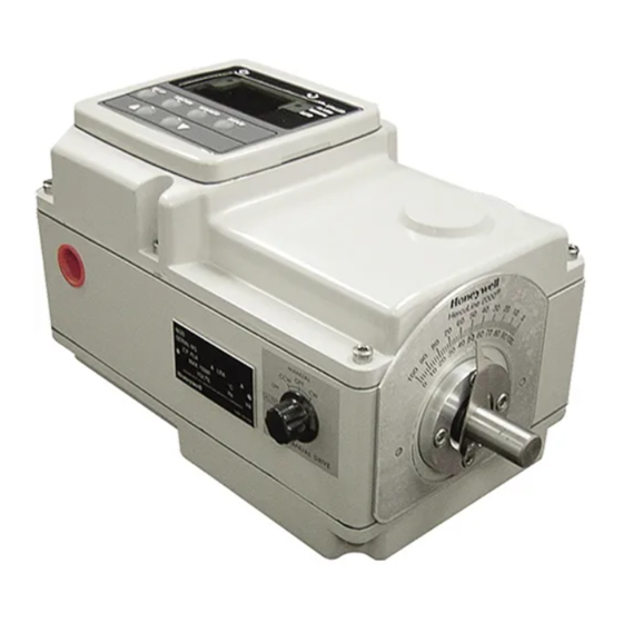
Introduction Product Description Introduction Product Description ® ® Honeywell’s HercuLine 2000 series actuators are available in four versions: HercuLine 2000, ® ® ® HercuLine 2001, HercuLine 2002, and HercuLine 2003. All are low torque, precision electric rotary actuators incorporating all of the high quality and reliable features of the traditional HercuLine series actuators. - Page 10 Introduction Product Description Display and keypad Handwheel Conduit entry Shaft and position indicator Auto/manual switch ® Figure 1 HercuLine 2000 Series Actuator HercuLine™ 2000 Series Actuator - Installation, Operation and Maintenance Manual Revision 7 7/08...
-
Page 11: Figure 2 Herculine ® 2002 Actuator Internal View
Introduction Product Description Display Display Wiring Wiring Keypad Keypad Label Label Mechanical Stops Mechanical Stops Connector Connector Cams and Cams and for customer for customer limit limit input and input and switches switches output output connection connection on CPU on CPU customer customer power... - Page 12 Introduction Product Description HercuLine™ 2000 Series Actuator - Installation, Operation and Maintenance Manual Revision 7 7/08...
-
Page 13: Specifications
Specifications Technical and Operating Specifications Specifications This section provides you with the technical specifications and the model selection guide for the ® HercuLine 2000 Series Actuators. Technical and Operating Specifications Table 1 Specifications - General Physical 2000: 25 lb. (11.36 kg) Weight 2001,2002: 27 lbs. - Page 14 Specifications Technical and Operating Specifications Electrical 100-130 Vac single phase, 50 Hz or 60 Hz Mains Supply 200-240 Vac single phase, 50 Hz or 60 Hz Instant start/stop, non-coasting, non-burnout, continuous duty, permanent Motor magnet, synchronous induction motor. Can be stalled up to 100 hours without damage.
- Page 15 Specifications Technical and Operating Specifications ® ® ® HercuLine 2002 HercuLine 2001 HercuLine 2000/2003 Slidewire emulation - Provides Feedback output voltage ratiometric to shaft position and potentiometric to supply voltage (1 Vdc to 18 Vdc) without a slidewire. Emulates a 100 ohm to 1000 ohm slidewire.
- Page 16 Specifications Technical and Operating Specifications ® ® ® HercuLine 2002 HercuLine 2001 HercuLine 2000/2003 Selectable and configurable operating parameters: Programmable Functions • Input range • Input filtering Input characterization • • Security • Digital Input action • Deadband • Failsafe on loss of input signal •...
- Page 17 At least 8 MB Serial port with RS232 compatible levels to drive external converter Communications Note: As of this writing only Palm devices have this feature. Honeywell has qualified the M105, M125, M130, and M505 devices with the HercuLink application. Revision 7 HercuLine™...
-
Page 18: Model Selection Guide
Specifications Model Selection Guide Model Selection Guide Instructions Select the desired key number. The arrow to the right marks the selection available. Make the desired selections from Tables I thru VIII using the column below the arrow. A dot ( ) denotes unrestricted availability. Key Number VIII _ _ _... - Page 19 Specifications Model Selection Guide 2000 2001 2002 2003 TABLE VI - OPTIONS Selection Local keypad/ No local display interface supplied 0_ _ _ _ _ (Note 2) display Integrally mounted local display/keypad interface 1_ _ _ _ _ Local Auto/ No auto/manual switch _ 0_ _ _ _ _ 1_ _ _ _...
-
Page 20: Installation
Installation Installation Overview Installation Installation Overview ® The procedures to install the HercuLine 2000 Series actuator and place it in service require that you: • Select a suitable location for installation. (See Installation Considerations below.) • Mount the actuator securely. •... -
Page 21: Before Starting
If there are visible signs of damage to the shipping container, notify the carrier and Honeywell immediately. If there is no visible damage, compare the contents with the packing list. Notify the carrier and Honeywell immediately if there is equipment damage or shortage. -
Page 22: Figure 3 Outline And Dimensions Of Herculine
Installation Actuator Mounting CLEARANCE FOR TOP REMOVAL: CLEARANCE FOR TOP REMOVAL: 101,6 101,6 11.379 11.379 25.4 25.4 1.00 1.00 inches ® Figure 3 Outline and Dimensions of HercuLine 2000 Series Actuators HercuLine™ 2000 Series Actuator - Installation, Operation and Maintenance Manual Revision 7 7/08... -
Page 23: Mechanical Installation
The actuator linkage can be set up to achieve an optimal delivered torque distribution for specific applications. To assist with linkage design, Honeywell offers a linkage analysis software application (HAL). The software can be ordered as P/N 51197910-001. -
Page 24: Figure 5 Variable Torque Linkage
Installation Mechanical Installation Vertical Vertical Centerline Centerline 45° 45° Actuator Linkage Crank Arm Close Open 5° Damper Horizontal Offset Crank Arm a/n 23200 Figure 5 Variable Torque Linkage Actuator Crank Arms ® The HercuLine 2000 Series Actuator comes standard with a crank arm with adjustable radius of 1.0 in (25.4mm) to 2.80 in (71.12mm). -
Page 25: Electrical Installation
Installation Electrical Installation Electrical Installation General Wiring Recommendations Only qualified personnel should perform wiring. Wiring must conform to national and local electrical codes. In general, copper wire used. Unless locally applicable codes dictate otherwise, the recommended minimum wire sizes in Table 2 should be observed. Table 2 Recommended Minimum Wire Size Description Earth ground wire to common power supply. -
Page 26: Table 3 Terminal Connections: Herculine ® 2000
Installation Electrical Installation ® HercuLine 2000 Terminal Connections ® Table 3 Terminal Connections: HercuLine 2000 Connection Terminal Numbers Descriptions and LABEL See Figure 8 Hot wire for 120/240VAC mains supply. Use only if Auto/Manual switch is present. Neutral Neutral wire for 120/240VAC mains supply Auto/Manual Switch Switch contact to indicate setting of actuator AUTO/MANUAL Contact... - Page 27 Installation Electrical Installation ® HercuLine 2001/2002 with Auto/Manual Terminal Connections ® Table 4 Terminal Connections: HercuLine 2001/2002 with auto/manual Connection Terminal Numbers Descriptions and LABEL See Figure 9 Hot wire for 120/240VAC mains supply Neutral Neutral wire for 120/240VAC mains supply Protective Ground Ground wire connection for mains supply Auto/Manual Switch...
-
Page 28: Figure 10 Herculine ® 2003 Connections
Installation Electrical Installation ® HercuLine 2003 Wiring Connections and Operation (Actionator 640D Replacement) Wiring ® Figure 10 HercuLine 2003 connections Operation The 2003 actuator is uni-directional (it does not reverse rotation with a reversal in control action). Figure 10 illustrates the internal wiring and the external connections. The smaller insert of the figure describes the limit switch action for one complete cycle. -
Page 29: Figure 11 Ce Wiring Part 1
Installation Electrical Installation Power Connections Depending on which power supply selection is ordered for your actuator, wire the power input (MAINS POWER) as described in the previous tables and figures. Wiring must conform to national and local electrical codes. CE Wiring When wiring the actuator power input for CE approved units, you must also install a MOV and ferrite beads supplied with the CE unit. -
Page 30: Figure 12 Ce Wiring Part 2
Installation Electrical Installation Step Action • AC power connection • Auxiliary switches connection Relay contact connection • Aux switches 1 and 2 (SW3 and SW4) Aux switches 3 and 4 (SW5 and SW6) Relays 1 and 2 Relays 3 and 4 AC power connection Figure 12 CE Wiring part 2... -
Page 31: Burner Control/Flame Safety
Burner Control/Flame Safety Electrical Installation Output Signal Connections 0/4-20 mA, 0/1-5 Vdc Feedback Signal Connections ATTENTION Shielded and grounded cables are recommended. Actuator output is a 4 to 20 mA analog signal. If a voltage input is required for customer devices, a range resistor is needed at the device input. -
Page 32: Series 90 Control - Herculine® 2001 Model Only
4/20 output. If help is required, contact Honeywell. 2. Due to variations in the definition of rotation directions, it may be necessary to reverse the action of the actuator from CCW to CW or vice versa. -
Page 33: Figure 15 T775 Controller Connections
Burner Control/Flame Safety Series 90 Control – HercuLine® 2001 model only Auto T775 B 3 I out from HercuLine2001 T775 W 1 + Signal to HercuLine2001 GND to HercuLine2001 (2) T775 R 2 Figure 15 T775 Controller connections 3. In the T775 controller manual there are several examples of using resistances or potentiometers as high and low limit controls. -
Page 34: Split Range
Burner Control/Flame Safety Split Range Split Range ® The HercuLine 2001/2002 actuators can be set up to operate within a narrow input range (for example, 4 to 12mA input) in certain applications. The procedure in Table 5 describes how to set up an actuator to operate as part of a split valve configuration. -
Page 35: Figure 16 Flow Diagram
Burner Control/Flame Safety Master/Slave Arrangement Basic Flow Control When the process variable signal is below set point, the controller increases current (4 to 20mA) to the actuator input and opens the valve. Controller set point governs valve position to obtain desired flow rate. -
Page 36: Figure 18 Proportional Flow Using Multiple Actuators
Burner Control/Flame Safety Master/Slave Arrangement Orifice Plate Positioner & Actuator Controller Valve 4 to 20 mA Linkage Linkage Valve Proportional Linkage Valve with Bias Ratio Position Figure 18 Proportional Flow Using Multiple Actuators Actuator #1 Current Output Controller 10260S Series Actuator #1 Jumper W2 = Current 120/240... -
Page 37: Figure 19 Multiple Actuator Interconnection Diagrams
Burner Control/Flame Safety Master/Slave Arrangement Current Output Controller Actuator #1 10260S Series Actuator #1 Jumper W2 120/240 Neutral = Current 250 Ohms 4 to 20 mA Ground 1 to 5 VDC 10260S Series Actuator #2 Actuator #2 120/240 Jumper W2 Neutral Ground = Voltage... -
Page 38: Figure 20 Interconnection Diagrams
Burner Control/Flame Safety Master/Slave Arrangement Split Valve Configuration A common heat or cool type process requires two valves. In this case the controller has only one output. The two motor positioners are calibrated differently, one responds to 4 to 12mA and the other responds to 12 to 20mA. -
Page 39: Set Up And Calibration Procedures
Set Up and Calibration Procedures Overview Set Up and Calibration Procedures Overview Once you have installed the actuator, you can verify, set or change certain operating parameters. Set up is ® accomplished through use of the local display and keypad interface through your PDA with HercuLink ®... -
Page 40: Table 6 Keypad Description
Set Up and Calibration Procedures Local Display and Keypad Table 6 Keypad Description Key or Function LED Indicator SET UP Places the actuator in the set up group select mode. Sequentially displays the set up groups and allows the FUNCTION key to display function parameters within the set up group. -
Page 41: Set Up Tips
Set Up and Calibration Procedures Set Up Tips Set Up Tips Table 7 contains tips that will help you view, verify and enter the operating parameters more quickly. If you cannot change the parameters, check the status of the “SET LOCK” parameter. Also some parameters require that you enter a security password before you access or change the parameter value. -
Page 42: Set Up Groups
Set Up and Calibration Procedures Set Up Groups Set Up Groups Pressing the SET UP key on the keypad provides access to the various set up groups and allows you to set up operating parameters, (such as input types and alarms), calibrate the actuator’s inputs and outputs, set communications, and check actuator status. - Page 43 Set Up and Calibration Procedures Set Up Groups Display various operating statistics. Reset Table 22 accumulated operating statistics MAINT Use the display as an indicator, (in this case a Table 23 voltmeter) so you can verify that the position sensor is POSOUT operating properly.
-
Page 44: Set Up Procedure
Set Up and Calibration Procedures Set Up Procedure Set Up Procedure Each of the set up groups and their functions are either pre-configured at the factory or set to their default values. Tables 8 through 19 list and describe the options available in each set up group. The following procedure shows you the key press sequence to access any set up group or any associated Function parameter. - Page 45 Set Up and Calibration Procedures Set Up Procedure Step Operation Press Result Change the Value These keys increase or decrease the value, or display the next or Selection available selection for the selected function prompt. See Table 7, Set Up Tips for instructions to increase or decrease a value quickly.
-
Page 46: Configuration Prompt Hierarchy
Set Up and Calibration Procedures Configuration Prompt Hierarchy Configuration Prompt Hierarchy Setup Groups Setup Groups Function Prompts Function Prompts IN TYP INP HI IN TYP INP HI INP LO INP LO FILTYP FILTYP Direct Direct Dband Dband FSTYPH FSTYPH FsVALH FsVALH INPUT INPUT... -
Page 47: Input Set Up Group
Set Up and Calibration Procedures Input Set Up Group Input Set Up Group Table 10 lists the parameters and selections available when the SET INPUT group is selected. On the keypad and local display: • Press the SET UP key to enter the Input Set Up group. •... - Page 48 Set Up and Calibration Procedures Input Set Up Group Actuator Lower Selections or Parameter Definition/PDA HercuLink Prompt Display Range of Setting Prompt INPUT FILTER TYPE— Allows the selection of a software NONE digital input filter to smooth the input signal. FILTYP Spike—...
- Page 49 Set Up and Calibration Procedures Input Set Up Group Parameter Definition/PDA HercuLink Prompt Actuator Lower Selections or Display Range of Setting Prompt FAILSAFELO TYPE—Selects the motor position you want the actuator to go to when input signal is below the low end FSFTYPL range value or on loss of input signal.
-
Page 50: Table 11 Equal Percentage Valve Characteristics
Set Up and Calibration Procedures Input Set Up Group Equal Percentage Valve Characteristic Table 11 contains values that approximate an equal percentage valve characteristic in the actuator. When the EQUL custom characterization type is selected, the values in Table 11 are automatically loaded into the actuator configuration to produce the characteristic as presented in the graph. -
Page 51: Table 12 Quick Opening Valve Characteristic
Set Up and Calibration Procedures Input Set Up Group Quick Opening Valve Characteristic Table 12 contains values that approximate the characteristic of a quick opening control valve. When the QUIK custom characterization type is selected, the values in Table 12 are automatically loaded into the actuator configuration to produce the characteristic as presented in the graph. -
Page 52: Relays Set Up Group
Set Up and Calibration Procedures Relays Set Up Group Relays Set Up Group ATTENTION The Relay set up group parameters are accessible only if relay PWAs are installed in the ® actuator. HercuLine 2001 actuators can be equipped with one PWA –for a total of two SPDT relays. -
Page 53: Table 14 Relay Type Descriptions
Set Up and Calibration Procedures Relays Set Up Group Table 14 Relay Type Descriptions When this Relay Type is selected… The Relay can be set up to indicate … (RTYP) The upper / lower limits of the input signal have been exceeded. Input Range Relay value parameter defines range limits and units are in percent of full span. -
Page 54: Figure 22 Relay Connectors
Set Up and Calibration Procedures Relays Set Up Group Relay connector #1 Relay connector #2 Relay connector #3 Relay connector #4 Figure 22 Relay connectors Relay Examples Relay Type - Position Range Selecting PosR relay type, you can cause the relay to energize when the actuator motor travels below 20% of range and above 80% of range. - Page 55 Set Up and Calibration Procedures Relays Set Up Group Relay Type - Deviation Setting up a relay to alarm (energize) when the motor position deviates 10% (+ or -) from the actuator setpoint can be set up as follows. Set Up Group Parameter Value SET RELAY1...
- Page 56 Set Up and Calibration Procedures Relays Set Up Group Relay Type – Upper Limit Travel with Hysteresis Selecting relay type ULim will cause the relay to energize when the motor position exceeds the upper limit trip point, and can be set up as follows. Note that relay hysteresis parameter (RLY1HY) value is set to 10, which is 10% of range.
-
Page 57: Current Out Set Up Group
Set Up and Calibration Procedures Current Out Set Up Group Current Out Set Up Group Table 15 lists the parameters and selections available for the SET CUROUT group. Table 15 Current Out Set Up Group Parameters Actuator Lower Selections or Parameter Definition/PDA HercuLink Prompt Display Range of Setting... -
Page 58: Communications Set Up Group
Set Up and Calibration Procedures Communications Set Up Group Communications Set Up Group Table 16 lists the parameters and selections available for the SET COMM group. Table 16 Communications Set Up Group Parameters Actuator Lower Selections or Parameter Definition/PDA HercuLink Prompt Display Range of Setting Prompt... -
Page 59: Digital Input Set Up Group
Set Up and Calibration Procedures Digital Input Set Up Group Digital Input Set Up Group Table 17 lists the parameters and selections availible for the SET DIGINP group. Table 17 Digital Input Set Up Group Parameters ® Actuator Lower Selections or Parameter Definition/PDA HercuLink Prompt Display... -
Page 60: Display Set Up Group
Set Up and Calibration Procedures Display Set Up Group Display Set Up Group Table 18 lists the parameters and selections availible for the SET DISPLAY group. Table 18 Display Set Up Group Parameters ® Actuator Lower Selections or Parameter Definition/PDA HercuLink Prompt Display Range of Setting... -
Page 61: Lock Set Up Group
Set Up and Calibration Procedures Lock Set Up Group Lock Set Up Group Table 19 lists the parameters and selections available for the SET LOCK group. Table 19 Lock Set Up Group Parameters ® Actuator Lower Selections or Parameter Definition/PDA HercuLink Prompt Display Range of Setting... - Page 62 Note: If the password can not be recovered to allow user access, a universal password can be obtained by calling the Honeywell Tactical Assistance center. Press the FUNCTION key, the lower display should read LOCK. The upper display should not be flashing.
-
Page 63: Read Status Set Up Group
Set Up and Calibration Procedures Read Status Set Up Group Read Status Set Up Group Table 20 lists the parameters and selections available for the READ STATUS group. Table 20 Read Status Set Up Group Parameters ® Actuator Lower Selections or Parameter Definition/PDA HercuLink Prompt Display... -
Page 64: Drive Set Up Group
Set Up and Calibration Procedures Drive Set Up Group Drive Set Up Group Table 21 lists the parameters and selections available for the SET DRVINF group. Table 21 Drive Set Up Group Parameters ® Actuator Lower Selections or Parameter Definition/PDA HercuLink Prompt Display Range of Setting... - Page 65 Set Up and Calibration Procedures Drive Set Up Group ® Actuator Lower Selections or Parameter Definition/PDA HercuLink Prompt Display Range of Setting Prompt DATE OF LAST REPAIR — Factory set only. Displays date LREP mmddyy * of last repair. ddmmyy DATE OF LAST FACTORY CALIBRATION —...
- Page 66 Set Up and Calibration Procedures Drive Set Up Group Set Tag Name The actuator tag name can be an alphanumeric name up to six characters. The tag name is set by using the keys on the keypad and the local display. Follow the steps below to set the tag name. Step Action Press SET UP key until the display reads SET DRVINF.
-
Page 67: Maintenance Set Up Group
Set Up and Calibration Procedures Maintenance Set Up Group Maintenance Set Up Group The Maintenance set up group consists of information about actuator operation accumulated through time. This information (or maintenance statistics) can be used to evaluate actuator operation and determine predicted or scheduled maintenance periods. - Page 68 Set Up and Calibration Procedures Maintenance Set Up Group ® Actuator Lower Selections or Parameter Definition/PDA HercuLink Prompt HercuLink ® PDA users: The prompts are organized differently on your PDA’s Display Range of Setting software. Grayed prompts are under Configuration, Maintenance. Non-grayed Prompt prompts are under Maintenance.
- Page 69 Set Up and Calibration Procedures ® Actuator Lower Selections or Parameter Definition/PDA HercuLink Prompt HercuLink ® PDA users: The prompts are organized differently on your PDA’s Display Range of Setting software. Grayed prompts are under Configuration, Maintenance. Non-grayed Prompt prompts are under Maintenance. RESTORE CALIBRATION TYPE —...
-
Page 70: Regions Of Motor Travel
Set Up and Calibration Procedures Regions of Motor Travel Regions of Motor Travel The full span of motor travel can be 90° or 150° rotation. The span is divided into 10 regions of motor travel as shown in Figure 23 (regions are numbered 0 through 9). Maintenance statistics are accumulated on the total number of motor starts, as well as the total number of motor starts that occur in each region of travel. -
Page 71: Cal Posout Group
Set Up and Calibration Procedures CAL POSOUT Group CAL POSOUT Group The CAL POSOUT group is used to verify that the position sensor is operating and adjusted properly. This group allows the local display to indicate the output voltage of the position sensor. This display is used when verifying the POS sensor is operating and that it is properly calibrated. -
Page 72: Auto - Manual Drive Switch
Set Up and Calibration Procedures Auto - Manual Drive Switch Auto - Manual Drive Switch The Auto - Manual switch is located on the side of the actuator case below the handwheel. The switch allows manual mode control of the actuator motor for set up, calibration and troubleshooting. Figure 24 shows an illustration of the Auto - Manual switch and Table 24 describes the switch settings. -
Page 73: Calibration
Set Up and Calibration Procedures Calibration Calibration ® Calibration of the HercuLine 2000 Series Actuator may consist of calibrating the motor circuit that positions the actuator with 0/4-20mA input signal, calibrating the potentiometer or non-contact sensor, and calibrating the slidewire emulation output or the 0/4-20mA output signal. Typically, only a motor calibration is required for installation. -
Page 74: Figure 25 Calibration Wiring Connections (Non-Slidewire Emulation)
Set Up and Calibration Procedures Calibration Calibration Set up Follow the steps below to set up the test equipment and actuator to verify calibration or perform calibration procedures. Step Action Determine input type (current or voltage). Set jumper W2 on main CPU board according to type of signal source. See Figure 27 on page 68 for jumper location. -
Page 75: Figure 26 Calibration Wiring Connections (Slidewire Emulation)
Set Up and Calibration Procedures Calibration Actuator Digital Voltmeter Calibrated Signal Terminal Block Source Input Output Power Supply 1-18 VDC Internal 250 ohm resistor settable through Jumper W2 Current Voltage Figure 26 Calibration Wiring Connections (slidewire emulation) Revision 7 HercuLine™ 2000 Series Actuator - Installation, Operation and Maintenance Manual 7/08... -
Page 76: Figure 27 Jumper Location On Cpu Pwa
Set Up and Calibration Procedures Calibration Jumper W2 Figure 27 Jumper Location on CPU PWA Calibrate Input ® The HercuLine 2001/2002 actuator accepts a variety of signal inputs. 1. 0 to 20 mA, or 4 to 20 mA 2. 0 to 5 Volts,1 to 5 Volts, or 0 to 10 Volts The input type is selected through the Input set up group using the local keypad. -
Page 77: Table 25 Input Calibration Procedure
Set Up and Calibration Procedures Calibration Table 25 Input Calibration Procedure Step Operation Press Result Enter Calibration SETUP Upper Display = Mode until you see Lower Display = INPUT FUNCTION Upper Display = Lower Display = CAL IN Upper Display = BEGN Lower Display = CAL IN... -
Page 78: Table 26 Motor Calibration Procedure
Set Up and Calibration Procedures Calibration Calibrate Motor Use the procedure in Table 26 to calibrate the actuator motor for 0% and 100% input signal ATTENTION For a motor calibration to be saved, you must complete the procedure. The calibration will not be saved if you exit without completing the steps of the procedure. -
Page 79: Table 27 Output Calibration Procedure
Set Up and Calibration Procedures Calibration Calibrate Output ® HercuLine 2001/2002 actuator can be one of three output types: 1. 0 to 20 mA, or 4 to 20 mA output 2. 0 to 5 Volts, or 1 to 5 Volts with 250 ohm range resistor 3. - Page 80 Set Up and Calibration Procedures Calibration Step Operation Press Result Calibrate Zero (0%) FUNCTION Upper Display = Lower Display = ZERO • Read meter connected to actuator output. • Adjust actuator output to a value equal to 0% output as read from the DVM.
-
Page 81: Table 28 Slidewire Emulation Calibration Procedure
Set Up and Calibration Procedures Calibration Table 28 Slidewire Emulation Calibration Procedure Step Operation Press Result Enter Calibration SETUP Upper Display = Mode until you see Lower Display = OUTPUT FUNCTION Upper Display = Lower Display = CALOUT Upper Display = BEGN Lower Display = CALOUT... -
Page 82: Table 29 Ncs Position Sensor Calibration Procedure
Set Up and Calibration Procedures Calibration While the unit is powered, a potentially lethal shock hazard exists inside the case. Table 29 NCS Position Sensor Calibration Procedure Step Action Remove AC power to the actuator. Remove the six screws and the top cover from the actuator case. See Figure 2. Lay extended cover assembly on a flat surface. -
Page 83: Figure 28 Location Of Ncs Assembly
Set Up and Calibration Procedures Calibration NCS set screw NCS PWA Relay PWA card guides (relay PWAs removed) NCS Spoiler (shown at full 150 degree travel CCW) Figure 28 Location of NCS Assembly Revision 7 HercuLine™ 2000 Series Actuator - Installation, Operation and Maintenance Manual 7/08... -
Page 84: Table 30 Potentiometer Position Sensor Calibration Procedure
Set Up and Calibration Procedures Calibration Table 30 Potentiometer Position Sensor Calibration Procedure Step Action Remove AC power to the actuator. Remove the six screws and the top cover from the actuator case. See Figure 2. Lay extended cover assembly on a flat surface. Remove relay cards if present. Reapply AC power to the actuator. -
Page 85: Table 31 Load Position Sensor Factory Calibration
Set Up and Calibration Procedures Calibration Potentiometer position sensor Mounting bracket Figure 29 Location of potentiometer position sensor Table 31 Load Position Sensor Factory Calibration Step Action Reapply AC power to the actuator. Press SET UP key to access the MAINT set up group. Press the FUNCTION key until the display reads LD CAL. -
Page 86: Setting End-Of-Travel Limit Switches
Set Up and Calibration Procedures Setting End-of-Travel Limit Switches Setting End-of-Travel Limit Switches ATTENTION Referring to Figure 31. The first two cams (starting from the front) are for the 0% and 100% limit switches (Switch #1 and Switch #2) and should not need any adjustments as they are factory set to stop the drive at 0% and 100%. -
Page 87: Table 32 End-Of-Travel Limit Switch Setting Procedure
Set Up and Calibration Procedures Setting End-of-Travel Limit Switches Table 32 End-of-Travel Limit Switch Setting Procedure Step Action Remove AC power to the actuator. Remove the six screws and the cover from the actuator case. See Figure 2. Lay cover assembly on a flat surface. -
Page 88: Figure 31 Location Of End-Of-Travel Limit And Auxiliary Switches
Set Up and Calibration Procedures Setting End-of-Travel Limit Switches ATTENTION Make sure you do not to set the switches too close to the hard stop. Relay PWAs Relay #1 End of travel switch #1 Relay #2 Aux switch #1 (stops CW rotation) Relay #3 Aux switch #2 End of travel switch #2... -
Page 89: Setting Auxiliary Switches
Set Up and Calibration Procedures Setting Auxiliary Switches Setting Auxiliary Switches ATTENTION Referring to Figure 31. The first two cams (starting from the front) are for the 0% and 100% end of travel limit switches (Switches #1 and #2) and should not need any adjustments as they are factory set to stop the actuator precisely at 0% and 100%. -
Page 90: Table 33 Auxiliary Switch Setting Procedure
Set Up and Calibration Procedures Setting Auxiliary Switches Table 33 Auxiliary Switch Setting Procedure Step Action Remove AC power to the actuator. Remove the six screws and the cover from the actuator case. See Figure 2. Lay cover assembly on a flat surface. Using a flat blade screwdriver on the slots on edge of cams, or your fingers, rotate the cams until the switches are set. -
Page 91: Start-Up/Operation
Start-Up/Operation Introduction Start-Up/Operation Introduction After the actuator is completely installed, wired, and the preliminary adjustments made, it is advisable to check the operation of the actuator and controlled device before placing it in service. In other words, operate the controlled device and check its direction of travel in response to an increase of the input signal and make sure it is correct for the process. -
Page 92: Operating Displays
Start-Up/Operation Operating Displays Operating Displays Pressing the DISPLAY key cycles the display through a number of operating parameters. Table 34 shows a number of sample displays that can be shown during operation. Table 34 Typical Operating Displays Display Description Input — Upper Display = Shows input value Lower Display = prompt Output —... -
Page 93: Position Sensor Operation
Start-Up/Operation Position Sensor Operation Position Sensor Operation ® ® On HercuLine 2000 and HercuLine 2001 the potentiometer position sensor is a sealed film pot that is directly ® coupled to the output shaft. On HercuLine 2002 the non-contact sensor (NCS) is inductively coupled to the output shaft of the actuator so that the sensor detects shaft position. -
Page 94: Figure 33 Terminal Block Connections For Modbus Communications
Start-Up/Operation Remote Setpoint Operation Actuator Terminal Block SHIELD DIGITAL INPUT COM M UNICATION Figure 33 Terminal Block Connections for Modbus Communications HercuLine™ 2000 Series Actuator - Installation, Operation and Maintenance Manual Revision 7 7/08... -
Page 95: Maintenance
Under normal operating conditions, the main worm gear should not require maintenance. Spur Gear Lubrication Honeywell recommends that during major shutdown periods the spur gears should be inspected and lubricated. Follow the steps in Table 35 to access the spur gear compartment and lubricate the gears if necessary. -
Page 96: Figure 34 Spur Gear Location
Maintenance Basic Maintenance Bottom cover Gears Idler spur gear Final output spur gear Motor pinion gear Figure 34 Spur Gear Location HercuLine™ 2000 Series Actuator - Installation, Operation and Maintenance Manual Revision 7 7/08... -
Page 97: Replacement Procedures
Remove power distribution PWA. Locate the two fuses on the power distribution PWA. See Figure 36. Carefully remove and replace fuse(s) with Wickmann T1 type 6A 250V, or equivalent (not available from Honeywell). Reinstall power distribution PWA. Reconnect connectors to CPU and power distribution PWA. -
Page 98: Table 37 Relay Pwa Replacement Procedure
Maintenance Replacement Procedures Fuses for Motor Drive Circuit Power Distribution PWA Figure 36 Motor Drive Circuit Fuses Relay PWA Replacement If a relay PWA needs to be replaced, follow the procedure in Table 37 to access and replace the PWA. Disconnect power before opening the actuator case. -
Page 99: Replacement/Upgrade/Accessory Kits
Replacement/Upgrade/Accessory Kits Replacement Kits Replacement/Upgrade/Accessory Kits Replacement Kits ® This section provides you with a complete list of all the spare parts that may be needed for the HercuLine 2000 Series Actuators and optional equipment. To determine which kit you need, cross-reference Figure 37 through Figure 41 with Table 38 on page 96. Each kit contains replacement parts accessories and instructions for component replacement. -
Page 100: Figure 38 Replacement Kit 10
Replacement/Upgrade/Accessory Kits Replacement Kits Figure 38 Replacement Kit 10 HercuLine™ 2000 Series Actuator - Installation, Operation and Maintenance Manual Revision 7 7/08... -
Page 101: Figure 39 Replacement Kits 1, 2, 3, 4, 5, 9, 15, 16, 19
Replacement/Upgrade/Accessory Kits Replacement Kits 4,5,9 Figure 39 Replacement Kits 1, 2, 3, 4, 5, 9, 15, 16, 19 Revision 7 HercuLine™ 2000 Series Actuator - Installation, Operation and Maintenance Manual 7/08... -
Page 102: Figure 40 Replacement Kit 13
Replacement/Upgrade/Accessory Kits Replacement Kits Figure 40 Replacement Kit 13 HercuLine™ 2000 Series Actuator - Installation, Operation and Maintenance Manual Revision 7 7/08... -
Page 103: Figure 41 Replacement Kits 17, 18
Replacement/Upgrade/Accessory Kits Replacement Kits 17, 18 Figure 41 Replacement Kits 17, 18 Revision 7 HercuLine™ 2000 Series Actuator - Installation, Operation and Maintenance Manual 7/08... -
Page 104: Table 38 Replacement Kits
Replacement/Upgrade/Accessory Kits Replacement Kits See Figure 37 through Figure 41 for drawings of replacement kit contents. Table 38 Replacement kits Qty/Unit Part Number Description Figure ID # 51450802-503 Relay Kit Relay Pwa Plug 03 Position Top Cover Gasket Qty/Unit Part Number Description Figure ID # 51451397-501... - Page 105 Replacement/Upgrade/Accessory Kits Replacement Kits Qty/Unit Part Number Description Figure ID # 51451656-506 1000 Ohm Potentiometer Kit 150 Degrees ® (HercuLine 2000) Pot 1 K Double 150 Degree #6-32 Hex Nut N #6 Washer #6 Lock Washer Machine Screw-Pan Hd-Cross Rec Top Cover Gasket Kit Instruction# 62-86-33-38 Qty/Unit...
-
Page 106: Table 38 Replacement Kits
Replacement/Upgrade/Accessory Kits Replacement Kits Qty/Unit Part Number Description Figure ID # 51452174-501 Crank Arm Kit Crank Arm Screw,Hex Hd,1 3/4 X 1/4-20 Kllwss1/4sp Nut Nmsndc 1/4-20 Qty/Unit Part Number Description Figure ID # 50011455-501 120vac/60HZ Motor Kit Motor 120v,50/60 Hz, Capacitor, 3 µfd 400Vac Cable plus Resistor assembly, 600 Ohm Resistor Bracket... - Page 107 Replacement/Upgrade/Accessory Kits Replacement Kits Qty/Unit Part Number Description Figure ID # Spur Gear Kit 51452443-501 51452443-507 51452443-508 51452443-509 51452443-510 51452443-511 Spur Gear 24p, 18t Spur Gear 24p, 18t Spur Gear 24p, 36t Spur Gear 24p, 72t Gear Assembly Gear Assembly Spur Gear 24p, 36t Bottom Cover Gasket Intermediate Shaft all except 7.5 seconds...
- Page 108 Replacement/Upgrade/Accessory Kits Replacement Kits Qty/Unit Part Number Description Figure ID # 51452443-504 Display and Keypad Kit Display Gasket Overlay, Display Lens, Display Gasket,Adhesive Die Cut Display Mtg Collar Machining Keypad, 6 Position Support Plate-Keypad Display Pwa Sems #4-40 X .310lg Pnphstl Screw,Metric Panhd,Cross Rec Split Washer Sleeve, Keypad...
- Page 109 Replacement/Upgrade/Accessory Kits Replacement Kits Qty/Unit Part Number Description Figure ID # 51452443-506 R/C Kit (Motor date codes after to 8/5/2005) Capacitor, 4.0 Mfd Cable plus Resistor, 400Ohm Capacitor, 3 Mfd, 400vac Cable plus Resistor, 600 Ohm Capacitor, 0.75 Mfd, 400vac Cable plus Resistor, 1100 Ohm Top Cover Gasket Bottom Cover Gasket...
-
Page 110: Upgrade Kits
Replacement/Upgrade/Accessory Kits Upgrade Kits Qty/Unit Part Number Description Figure ID # 51500581-504 Auto/Manual Switch (upgrade for SA2001 & SA2002) Auto/Manual Label Nut, Sealing 3/8-32 Thrd Knob A/M Switch/Wire Assy Label, Customer Wiring, Top Cover Gasket Upgrade Kits Qty/Unit Part Number Description 51452444-502 Cover (with Display no Handwheel) - Page 111 Replacement/Upgrade/Accessory Kits Upgrade Kits Qty/Unit Part Number Description 51452444-503 Cover with Display and Handwheel Display gasket Overlay, display Lens, display Gasket,adhesive die cut Display mtg collar machining Keypad, 6 position Support plate-keypad Display PWA Top cover w/display & hndwheel Sems #4-40 x .310lg pnphstl Screw,metric panhd,cross rec Hand wheel O-ring buna n...
-
Page 112: Accessory Kits
Replacement/Upgrade/Accessory Kits Accessory Kits Qty/Unit Part Number Description 51451656-511 1000 ohms 150 degrees upgrade kit Machine screw-pan hd-cross rec Knob Bracket molding Pot 1K double 150 degree #6 lock washer Machine screw-pan hd-cross rec #6-32 hex nut N Stainless steel pin 3/32x4-40 setscrew sshxsocupsb Washer #6 Flat washer M4 (zinc) -
Page 113: Troubleshooting
Troubleshooting Introduction Troubleshooting Introduction Troubleshooting procedures can be followed when inaccurate or faulty actuator operation is detected. In this section, troubleshooting procedures consist of a few simple flow charts to test for proper function of various actuator components. Component replacement is at the PWA or assembly level. Table 39 indicates some of the observable symptoms of failure that can be identified by noting the faulty actuator operation. -
Page 114: Troubleshooting Procedures
Troubleshooting Troubleshooting Procedures Troubleshooting Procedures Overview Follow the procedure or flow chart to test for and determine actuator component operation. When using the flow charts for troubleshooting, you may be instructed to go to another flow chart in order to identify the faulty component. -
Page 115: Figure 42 Test For Actuator Operation
Troubleshooting Troubleshooting Procedures Test for Actuator Operation Cycle power to actuator. Does display light up? Move handwheel Observe self test. on actuator 2 or 3 turns. Does motor reposition Do all diagnostics pass? itself? RAMTST PASS SEETST PASS CALTST PASS CFGTST PASS Replace display All LEDs and... -
Page 116: Figure 43 Power Up Diagnostics
Troubleshooting Troubleshooting Procedures Power Up Self Test Diagnostics Cycle power to actuator. Does display light up? Observe self test. RAMTST PASS? Replace CPU SEETST PASS? Assembly. Check actuator Cycle power to configuration actuator. If CFGTST CFGTST PASS? (setup), reconfigure fails again, replace if necessary. -
Page 117: Figure 44 Test Power Distribution Pwa
Troubleshooting Troubleshooting Procedures Test Power Distribution PWA Remove top cover of actuator. Check Fuses F1 and F2 on the power distribution PWA. Are fuses good? Replace fuses with same type and rating Is correct voltage present at test points? See below. Replace Power Replace CPU Distribution PWA. -
Page 118: Figure 45 Test Auto - Manual Switch
Troubleshooting Troubleshooting Procedures Test AUTO - MANUAL DRIVE Switch Turn switch to Manual CCW setting. Does motor drive in the CCW direction? Turn switch to Manual CW setting. Does motor drive in the CW direction? Possible trouble spots a. Auto/Manual switch b. -
Page 119: Figure 46 Test Relay Function
Troubleshooting Troubleshooting Procedures Test Relay Function Press SET UP button on keypad to enter Set up mode. Set suspect Relay Set AUTO - type to MAN. MANUAL switch to MAN. Place ohmmeter across associated relay contacts at Does Relay Actuator terminal operate? block. -
Page 120: Appendix A - Herculine 2001/2002 Configuration Record Sheet
Appendix A - HercuLine® 2001/2002 Configuration Record Sheet ® Appendix A - HercuLine 2001/2002 Configuration Record Sheet Enter the value or selection for each set up parameter on this sheet so you will have a record of how your actuator is configured. Set Up Group Parameter Setting... - Page 121 Appendix A - HercuLine® 2001/2002 Configuration Record Sheet Set Up Group Parameter Setting Default Prompt X19 VAL - User configurable characterizer value __________________ 95.0 X20 VAL - User configurable characterizer value __________________ 100.0 Y0 VAL -- User configurable characterizer value __________________ Y1 VAL -- User configurable characterizer value __________________...
- Page 122 Appendix A - HercuLine® 2001/2002 Configuration Record Sheet Set Up Group Parameter Setting Default Prompt RTYP31 – Relay Type __________________ NONE R31VAL – Relay Value __________________ R31 HL – Relay High/Low __________________ R31SCALE– Relay Scale __________________ RTYP32 – Relay Type __________________ NONE R32VAL –...
- Page 123 Appendix A - HercuLine® 2001/2002 Configuration Record Sheet Set Up Group Parameter Setting Default Prompt VERSON – Firmware Version __________________ Read Only SET DRVINF SPEED – Stroke Speed __________________ Factory Set POWER – Power Input Voltage Line Frequency __________________ Factory Set TAG –...
-
Page 124: Index
Index Index Actuator Rotation, 40, 64 Deadband, 7, 40 Actuator Set Up, 33 Decimal Point Location, 52 Set up groups, 34 Deviation, 45 Set up procedure, 36 Relay type, 47 Actuator Statistics Device Address, 50 Accumulated motor starts, 59 Direction of Rotation, 7 Motor starts, 59 Duty Cycle, 7 Relay cycle counts, 59... - Page 125 Index Inputs, 39 Output Calibration, 71 Installation, 12 Output Shaft, 5 Installation Considerations, 13 Output Torque, 5 Isolation, 6 Output Type, 49 Outputs, 49 Keypad, 8, 31 Description, 32 Password, 60 (LOCKID), 53 Change, 54 PDA, 9 Position Range LEDs on Local Display, 32 Relay type, 46 Limit Switches, 78 Position sensing, 7...
- Page 126 Index Stall, 84 Equipment, 106 Start Up Checklist, 83 Storage Temperature, 5 Stroke Speed, 56 Voltage/ Supply Stability, 7 Tag Name, 58 TAG parameter, 56 Weight, 5 Technical and Operating Specifications, 5 Temperature Coefficient, 7 Terminal Connections, 18, 19 Total Degrees of Motor Travel Zero Suppression, 7 TOTDEG parameter, 59 Troubleshooting, 105...
- Page 127 Revision 7 HercuLine™ 2000 Series Actuator - Installation, Operation and Maintenance Manual 7/08...
- Page 128 Honeywell Process Solutions Industrial Measurement and Control 512 Virginia Drive Fort Washington, PA 19034 http://hpsweb.honeywell.com 62-86-25-10 0708 Printed in USA...