Table of Contents
Advertisement
[1] NOTE FOR SERVICING. . . . . . . . . . . . . . . . . . . . . . . . . . . . . . . . . 1-1
[2] SYSTEM CONFIGURATION . . . . . . . . . . . . . . . . . . . . . . . . . . . . . 2-1
[3] SPECIFICATIONS . . . . . . . . . . . . . . . . . . . . . . . . . . . . . . . . . . . . . 3-1
[4] CONSUMABLE PARTS . . . . . . . . . . . . . . . . . . . . . . . . . . . . . . . . . 4-1
[5] UNPACKING AND INSTALLATION . . . . . . . . . . . . . . . . . . . . . . . . 5-1
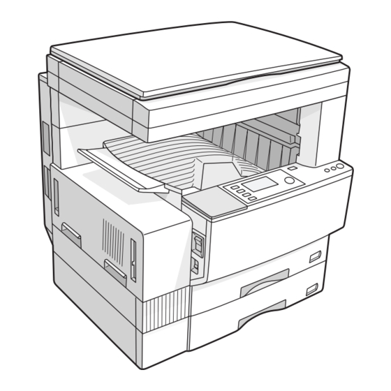
[6] EXTERNAL VIEW AND INTERNAL STRUCTURE . . . . . . . . . . . . 6-1
[7] ADJUSTMENTS, SETTING . . . . . . . . . . . . . . . . . . . . . . . . . . . . . . 7-1
[8] SIMULATION . . . . . . . . . . . . . . . . . . . . . . . . . . . . . . . . . . . . . . . . . 8-1
[9] TROUBLE CODE LIST. . . . . . . . . . . . . . . . . . . . . . . . . . . . . . . . . . 9-1
[10] DISASSEMBLY, ASSEMBLY AND MAINTENANCE . . . . . . . . . . 10-1
[11] OTHERS . . . . . . . . . . . . . . . . . . . . . . . . . . . . . . . . . . . . . . . . . . . . 11-1
Parts marked with "
" are important for maintaining the safety of the set. Be sure to replace these parts with
specified ones for maintaining the safety and performance of the set.
SERVICE MANUAL
DIGITAL LASER COPIER/
PRINTER
CONTENTS
SHARP CORPORATION
CODE: 00ZAR5127/A1E
AR-5127
MODEL
This document has been published to be used
for after sales service only.
The contents are subject to change without notice.
Advertisement
Table of Contents

Related Manuals for Sharp AR-5127


Summary of Contents for Sharp AR-5127
-
Page 1: Service Manual
CODE: 00ZAR5127/A1E DIGITAL LASER COPIER/ PRINTER AR-5127 MODEL CONTENTS [1] NOTE FOR SERVICING....... . . 1-1 [2] SYSTEM CONFIGURATION . - Page 2 CAUTION This product is a class 1 laser product that complies with 21CFR 1040.10 and 1040.11 of the CDRH standard and IEC825. This means that this machine does not produce hazardous laser radiation. The use of controls, adjustments or performance of procedures other than those specified herein may result in hazardous radiation exposure.
-
Page 3: Table Of Contents
CONTENTS [1] NOTE FOR SERVICING [6] EXTERNAL VIEW AND INTERNAL STRUCTURE 1. Warning for servicing ......1-1 1. -
Page 4: Note For Servicing
8) The machine has got sharp edges inside. Be careful not to dam- CAUTION: If this CAUTION should be ignored, an injury or a age fingers when servicing. -
Page 5: System Configuration
CN121 CN107 CN102 SENSOR TRAYPAPER CN135 CN111 CN136 ONLY) Area (INCH CN125 ONLY) Area CN130 CN139 CN134 CN132 CN113 Sensor Full Paper SENSOR COVER POUT Sensor Pout CN28 Solenoid CN131 Gate Pout CN123 CN115 AR-5127 SYSTEM CONFIGURATION 2 - 1... -
Page 6: System Outline (Options)
Reversing single pass feeder Single pass feeder 500-sheet paper feed unit 2X500-sheet paper feed unit AR-TR3 AR-FN5N AR-FX4 AR-EB4 Job separator tray kit Finisher Facsimile expansion kit Dual function board AR-MM5/MM6/MM7 2/4/8MB Fax memory AR-5127 SYSTEM CONFIGURATION 2 - 2... -
Page 7: Specifications
Standard: 50 to 400% (50 to 200% for SPF/ RSPF) 95% to 105% 5.0 line/mm 4.5 line/mm With AR-EB4 installed: 25 to 400% (50 to 106% to 141% 5.0 line/mm 4.5 line/mm 200% for SPF/RSPF) 142% to 400% 5.0 line/mm 4.5 line/mm AR-5127 SPECIFICATIONS 3 - 1... -
Page 8: Engine Specifications
(3) Resolution b. Simultaneous wrapping in kit Main scanning direction Sub scanning direction Job separator tray Scan 400 dpi 600 dpi Setting manual book (4) Gradation c. Simultaneous wrapping 256 gradations (8-bit) Setting manual book AR-5127 SPECIFICATIONS 3 - 2... -
Page 9: D. Scanner (Exposure) Section
(–) DC scorotron (saw tooth) Temperature (˚C) Voltage 560 A constant electric current Transfer System Transfer roller Voltage 18 A (electric current) Exposure Xenon lamp Developing Dry, 2-component magnetic brush development Separation (–) DC corotron Discharge — Cleaning Blade AR-5127 SPECIFICATIONS 3 - 3... - Page 10 (3) Ambient storage conditions Temperature (˚C) (4) Ambient conditions for transporting Temperature (˚C) (5) Atmospheric pressure 595 mmHg or above (6) Standard temperature and humidity Temperature 20 to 25°C Humidity 65±5%RH AR-5127 SPECIFICATIONS 3 - 4...
-
Page 11: Consumable Parts
4 times. (Supplied as a drum frame unit.) * Drum frame unit contains all the drum unit parts excluding Drum and Drum fixing plate. * The other maintenance parts than the above are supplied as service parts. AR-5127 CONSUMABLE PARTS 4 - 1... -
Page 12: C. Asia Affiliates/Asia Agent/Stcl/Srh/Srs/Srssc/Sbi
* Drum frame unit contains all the drum unit parts excluding Drum and Drum fixing plate. 10 Staple Cartridge Staple Cartridge ×3 3000 staples AR-SC1 ×3 * The other maintenance parts than the above are supplied as service parts. AR-5127 CONSUMABLE PARTS 4 - 2... -
Page 13: Production Number Identification
The prodoction month. X stands for October, Y November, and Z December. 4. Life (packed conditions) 3, 4 Production date. Photoconductor drum (36 months from the production month) Developer, toner (24 months from the production month) AR-5127 CONSUMABLE PARTS 4 - 3... -
Page 14: Unpacking And Installation
6) Attach the developer cartridge to the copier, and fix it with the screw. Note: When replacing the OPC drum with a new one, be sure to clear the drum count. AR-5127 UNPACKING AND INSTALLATION 5 - 1... -
Page 15: Toner Cartridge Installation
2) To select the paper size from the operation panel, press the Spe- cial Function key and choose "Paper Size Enter" from the function menu to open the paper size enter screen. AR-5127 UNPACKING AND INSTALLATION 5 - 2... -
Page 16: External View And Internal Structure
Fusing unit release levers Lower to remove misfed paper. Photoconductor drum A drum on which photoconductor is coated. Images are formed on this photoconductor drum. Roller rotating knob Turn to remove misfed paper. AR-5127 EXTERNAL VIEW AND INTERNAL STRUCTURE 6 - 1... -
Page 17: Operation Panel
Displays the selected paper size. When "AUTO" is displayed, paper size matching the original and copy ratio will be automatically selected. Paper tray display The selected paper feed location is highlighted. AR-5127 EXTERNAL VIEW AND INTERNAL STRUCTURE 6 - 2... -
Page 18: Motor, Solenoid, Clutch
Manual feed tray tray empty sensor 1 position detection Manual feed length HPSIZE2 Manual feed paper detection sensor 2 length detection Manual feed length HPSIZE1 Manual feed paper detection sensor 1 length detection AR-5127 EXTERNAL VIEW AND INTERNAL STRUCTURE 6 - 3... -
Page 19: Pwb Unit
Power source PWB AC power input/DC voltage MG roller Puts toner on the OPC drum. control 2nd/3rd mirror unit Reflects the images from the copy lamp unit to the lens unit. AR-5127 EXTERNAL VIEW AND INTERNAL STRUCTURE 6 - 4... -
Page 20: Adjustments, Setting
4) Check the clearance of the developing doctor. If it is within the specified range, then fix the doctor fixing screw with screw lock. When inserting a thickness gauge, be careful not to scratch the developing doctor and the MG roller. AR-5127 ADJUSTMENTS 7 - 1... -
Page 21: B. Mechanism Section
Super photo Disabled 5:SUPER PHOTO items range Toner save 2 (–505V) 6:TONER SAVE 1st cassette 0-99 1:TRAY1 The input value is in the increment of –25V. Option cassette 1-99 2:OPTION Manual feed 3:MANUAL Back print 4:DUPLEX AR-5127 ADJUSTMENTS 7 - 2... - Page 22 Pressing the [START] key makes a print. paralleled with the edge lines. Pressing the [RETURN] key returns to the mode selection. 2) Make a copy, then use the copy output as an original to make an SPF copy again. AR-5127 ADJUSTMENTS 7 - 3...
- Page 23 0.5 – 4mm 1 – 99 (7) Main scanning direction (FR direction) distortion balance adjustment 1) Remove the OC glass and the right cabinet. 2) Loosen the copy lamp unit wire fixing screw. Wire fixing screw AR-5127 ADJUSTMENTS 7 - 4...
- Page 24 1) Set A3 (11" x 17") white paper on the original table as shown below. Place a little clearance from the rear side original guide. Glass holding plate A3 (11" x 17") white paper Fit the paper edge and the glass holding plate edge. AR-5127 ADJUSTMENTS 7 - 5...
- Page 25 This adjustment must be performed in the following cases: • When the mirror base wire is replaced. • When the copy lamp unit and no. 2/3 mirror unit are replaced. • When the mirror unit rail is replaced and moved. AR-5127 ADJUSTMENTS 7 - 6...
- Page 26 The current front surface sub scanning direction magnification ratio Main scanning At normal: 48-1 Add 1: 0.1% 1 – 99 correction value is displayed in two digits on the display section. direction ±1.0% increase magnification Reduce 1: 0.1% ratio decrease AR-5127 ADJUSTMENTS 7 - 7...
- Page 27 SIM. • When the display is 143 or below: 1) Remove the table glass. 2) Remove the dark box. 3) Slide the lens unit toward the rear side and attach it, then exe- cute SIM. AR-5127 ADJUSTMENTS 7 - 8...
-
Page 28: C. Image Density (Exposure) Adjustment
5) Change the initial value of the SPF exposure adjustment (SIM46- 20) from 50 to 53. (For the CCD exposure adjustment with SPF, use the value of the OC adjustment value +3.) There are suffixes of –1 SPF and –2 SPF. Change each of them. AR-5127 ADJUSTMENTS 7 - 9... -
Page 29: Simulation
Input value clear number of times 10-key Entry of the number of times Display check system Shifts to the magnification ration selection screen. Screen Function Display check Cancel simulation Interrupt Sub code input screen appears. AR-5127 SIMULATION 8 - 1... -
Page 30: Simulation Code List
(The the control circuit. toner concentration sensor output can be Used to check and adjust the operation of the main monitored.) charger grid voltage (low mode) in FAX mode and the control circuit. AR-5127 SIMULATION 8 - 2... - Page 31 (When the print image position The AD conversion value of manual feed width varies greatly for the paper or when a lot of paper detection is displayed. jam troubles occur, the adjustment is required.) AR-5127 SIMULATION 8 - 3...
-
Page 32: Details
Set a document on the APF paper feed tray, and fix it with tape. Enter the number, set the magnification ratio and the original size and press the [OK] key, and the SPF unit will operate in a speed corre- sponding to the setup. AR-5127 SIMULATION 8 - 4... - Page 33 4:FM-1200 The motor for 10sec, the solenoid ON for 500msec, OFF for 500msec. Tray lift-up motor 5:EVM (20 times) Tray offset motor 6:OFM Note: Executable only when the SPF/RSPF is installed. Staple operation motor 7:STM AR-5127 SIMULATION 8 - 5...
- Page 34 Note: Executable only when the finisher is installed. tray cannot descend to the specified posi- tion. Check to insure that there is no paper in the tray before execution. Note: Executable only when the finisher is installed. AR-5127 SIMULATION 8 - 6...
- Page 35 Green" every 2 3rd cassette right door detection sensor DSWR3 seconds. 2nd cassette right door detection sensor DSWR2 4th cassette right door detection sensor DSWR4 Note: Execution is possible only when the option cassette is installed. AR-5127 SIMULATION 8 - 7...
- Page 36 6:DV CHK. 2nd cassette lift-up motor 8:LUM2 Press [CA] key, and the simulation will be terminated and copying will 2nd cassette pick-up solenoid 9:CPFC2 be made with the set contents. 2nd cassette paper feed clutch 10:CPFS2 AR-5127 SIMULATION 8 - 8...
- Page 37 (Only the adjustment value can be entered.) Section Image process (Photoconductor/Developing/Transfer/ Cleaning) Developer/Toner hopper Operation/procedure After selecting the mode, enter the adjustment value and press the [OK] key, and output will be made for 30sec. AR-5127 SIMULATION 8 - 9...
- Page 38 *2. The set values can be selected from the above 8 patterns only. *3. The selected pattern determines the grid high voltage and the grid low voltage. If, for example, the grid high voltage is set to –480V (pattern 1), the grid low voltage is –350V. AR-5127 SIMULATION 8 - 10...
- Page 39 Density 1 (1200dpi) Disabled 7:DENS1(1200) Density 2 (1200dpi) Disabled 8:DENS2(1200) Density 3 (1200dpi) Disabled 9:DENS3(1200) EXEC [ 1- 8] EXEC [ 1- 8] Density 4 (1200dpi) Disabled 10:DENS4(1200) Density 5 (1200dpi) Disabled 11:DENS5(1200) Setting range Default AR-5127 SIMULATION 8 - 11...
- Page 40 Used to check and adjust the operation of the load play returns to the main code entry screen. (Purpose) (motor) in the duplex section and the control circuit. Section Duplex Item Operation Operation/procedure Select with the 10-key and operate for 30 seconds. AR-5127 SIMULATION 8 - 12...
- Page 41 Sim17 TROUBLE CLEAR rate is obtained by dividing this count value with the PF TROUBLE CLEAR PF TROUBLE CLEAR total counter value.) Item Trouble PRESS OK KEY ARE YOU SURE? Operation/procedure Counter data is displayed. AR-5127 SIMULATION 8 - 13...
- Page 42 P-IN sensor Manual feed P-IN Not reached FIN_P_OFSET sensor. PIN_DUP reversion jam sensor (DUP) Duplex sensor P-IN sensor or Reached DPX_TOP lead edge jam manual feed P-IN sensor DUP sensor Not reached (Paper exit sensor) AR-5127 SIMULATION 8 - 14...
- Page 43 Used to check the number of use of each paper feed (Purpose) section. (the number of prints) UE1/UE4/ UW2/SL4/ Section Paper feed Item Counter SEEG CG/GD English, German, Turkish, Greek, Polish, Hungarian, Czech DG/DD English, German, Swedish, Finnish, Norwegian, Danish AR-5127 SIMULATION 8 - 15...
- Page 44 For the cassettes, only the option cassette is displayed. Counter data is displayed. * Execution is inhibited until GDI or PCL board is securely installed. (Because the board is detected by the software.) Sim22-19 SCAN MODE SCANMODE:nnnnnnnnn Scanner mode counter SCANMODE AR-5127 SIMULATION 8 - 16...
- Page 45 Item Counter Scan counter 2:SCAN Operation/procedure 3:STAPLE Stapler counter Press the [OK] key. (Initial screen) (Check screen) Sim24-7 COUNTER CLR Sim24-7 COUNTER CLR DRUM COUNTER CLEAR DRUM COUNTER CLEAR PRESS OK KEY ARE YOU SURE? AR-5127 SIMULATION 8 - 17...
- Page 46 [CA] key, and concentration sensor output can be monitored.) execute SIM 25-2 again. Section DRIVE • "DEVE UNIT NONE" Item Operation Error content: Occurs when the developing unit is not installed in an AR model. AR-5127 SIMULATION 8 - 18...
- Page 47 LG (8.5” x 14”) LG (8.5” x 14”) FC (8.5” x 13”) Inch series FC (8.5” x 13”) LG (8.5” x 14”) FC (8.5” x 13”) LG (8.5” x 14”) LG (8.5” x 14”) FC (8.5” x 13”) AR-5127 SIMULATION 8 - 19...
- Page 48 JOBSEP OUT MODE Setting range (0:OFF 1:ON) Default (Initial screen) (Input screen) [ 0- 1] Sim26-5 COUNT MODE Sim26-5 COUNT MODE 1:TOTAL COUNTER 2:MAINTE COUNTER 1 2:MAINTE COUNTER 1 (1:SINGLE COUNT 2:DOUBLE COUNT) [ 1- 2] AR-5127 SIMULATION 8 - 20...
- Page 49 [ 0- 1] Default Display items Content Setting range Default Display items Setting range Japan, SEC, SECL, Others Stop 0:STOP SCA, SEF, Taiwan Non stop 1:NON STOP 0:OFF Note: Executable only with CRU (DM models). 1:ON AR-5127 SIMULATION 8 - 21...
- Page 50 This setup varies in connection with SIM 26-6 (Destination setup). 26-50 Purpose Setting Sim26-60 FAX KEY Function Used to set whether to use the black/white reverse FAX KEY SETTING (Purpose) function. (0:ON 1:OFF) Item Operation [ 0- 1] AR-5127 SIMULATION 8 - 22...
- Page 51 Used to check the operation of sensors and detectors (Purpose) in the sections other than the paper feed section of the copier and the related circuit. (The operation of sensors and detectors can be monitored with the LCD.) Section Others Item Operation AR-5127 SIMULATION 8 - 23...
- Page 52 Sim40-2 MB SENSOR Section Others A4R PAPER SET LTR PAPER SET Item Operation PRESS OK KEY PRESS OK KEY If the intermediate position adjustment is not performed, press the [OK] key without changing the guide position. AR-5127 SIMULATION 8 - 24...
- Page 53 The value in [ ] shows the threshold value of 20 degree detection Sim43-10 POST CARD adjustment. PICK UP CYCLE For AB series, 1 - 5 is displayed, for inch series, PD1 - 4. [ 1- 99] Setting range 1-99 Default AR-5127 SIMULATION 8 - 25...
- Page 54 10:+V2 S-F(1200) 1200dpi +V2 small size front 5-30 Disabled Character/Photo (TS) Level 3.0 8:TEXT/PHOTO(TS) 11:+V2 S-R(1200) 1200dpi +V2 small size 5-30 Disabled Setup of various copy conditions: Similar to the normal copy mode. back 12:+V2 OHP(1200) 1200dpi +V2OHP 5-30 Disabled AR-5127 SIMULATION 8 - 26...
- Page 55 Setup of various copy conditions: Similar to the normal copy mode. Use of [SPECIAL FUNCTION] key, [JOB STATUS] key, and [INTER- Use of [SPECIAL FUNCTION] key, [JOB STATUS] key, and [INTER- RUPT] key is inhibited. RUPT] key is inhibited. AR-5127 SIMULATION 8 - 27...
- Page 56 When [OK] or [START] key is pressed, a caution buzzer sounds. (Fine) Manual (46-13 to 16) (Only the adjustment value can be entered.) Auto Manual U-fine Auto (Super fine) Manual Auto Manual When initializing each data: 50 Note: Executable only when the FAX is installed. AR-5127 SIMULATION 8 - 28...
- Page 57 Content Setting range Default Setup of various copy conditions: Similar to the normal copy mode. 1-99 1:SPF EXPOSURE Use of [SPECIAL FUNCTION] key, [JOB STATUS] key, and [INTER- RSPF 2:RSPF EXPOSURE RUPT] key is inhibited. AR-5127 SIMULATION 8 - 29...
- Page 58 (Abnormal end screen) Sim48-3 READ AUTO Sim48-3 READ AUTO RRC-A [ 32] RRC-A [ ERR] OC Center [ 53] OC Center [ ERR] MirSpeed [ 58] MirSpeed [ ---] PRESS OK KEY EXEC PRESS OK KEY EXEC AR-5127 SIMULATION 8 - 30...
- Page 59 Use of [SPECIAL FUNCTION] key, [JOB STATUS] key, and [INTER- loss quantity set value RUPT] key is inhibited. Setup of various copy conditions: Similar to the normal copy mode. Use of [SPECIAL FUNCTION] key, [JOB STATUS] key, and [INTER- RUPT] key is inhibited. AR-5127 SIMULATION 8 - 31...
- Page 60 Used to adjust the print image center position. (Purpose) (Adjustment can be made for each paper feed Use of [SPECIAL FUNCTION] key, [JOB STATUS] key, and [INTER- section.) RUPT] key is inhibited. Section Image processing (ICU) Item Picture quality Image position AR-5127 SIMULATION 8 - 32...
- Page 61 Tray selection: 4:TRAY3 3rd cassette is specified. 4th cassette 1-99 Tray selection: 5:TRAY4 4th cassette is specified. Back print 1-99 Tray selection: 6:DUPLEX Made by user. SPF front 1-99 Tray selection: 7:SPF(SIDE1) surface Made by user. AR-5127 SIMULATION 8 - 33...
- Page 62 Interruption is inhibited Sim61-1 LSU CHECK Sim61-1 LSU CHECK during execution. During execution, [EXEC] is highlighted. EXEC PRESS OK KEY EXEC (Result screen/Normal) (Result screen/Abnormal) Sim61-1 LSU CHECK Sim61-1 LSU CHECK COMPLETE EXEC ERROR EXEC AR-5127 SIMULATION 8 - 34...
- Page 63 66-4 Purpose Adjustment/Setting/Check Function Signal send mode (Purpose) Related soft SW5-5 to 8 (signals send level) SW23-1 to 4 (RBT ON time) SW23-5 to 8 (RBT OFF time) SW43-1 to 5 (DTMF signal send time) AR-5127 SIMULATION 8 - 35...
- Page 64 100 digits can be sent from the line. • When "*" and "#" are included in the registered dial number, they are disregarded and the number is not processed as a dial. AR-5127 SIMULATION 8 - 36...
- Page 65 Used to print the system error log (error simulation process but in the normal screen number and time). For this operation, the and measure the time. system error log is always stored as the ring buffer in the SRAM 256byte area. AR-5127 SIMULATION 8 - 37...
- Page 66 1. Detected signal Detected in off-hook. CI, CNG, FNET, DTMF S M L Detected in off-hook. BusyTone, CNG DialTone, CED SDT, flag, DTMF S M L S M L CI displays the detected ring pattern simultaneously. AR-5127 SIMULATION 8 - 38...
- Page 67 3) For the management information, refer to the table below. ory into the SRAM of the FAX board. However, the FAX program version No. area is written into the data Note: Executable only when the FAX is installed. version no. area (FFF0 - FFFF). AR-5127 SIMULATION 8 - 39...
-
Page 68: Trouble Code List
(Timeout) The entered directory of the FTP server Network Machine-FAX board language error is invalid. Developer adjustment trouble (Over- toner abnormality) Developer adjustment trouble (Under- toner abnormality) RIC copy inhibit signal received AR-5127 TROUBLE CODE LIST 9 - 1... -
Page 69: Self Diagnostics
Check Check installation of the expanded memory module. (Spec: Added to Slot 1.) remedy Replace the expanded memory module. Replace the IMC PWB. Remarks Extend memory abnormality for compressed image store (DIMM module) AR-5127 TROUBLE CODE LIST 9 - 2... - Page 70 SPF scan position.) operation. Check "Clean the mirror, the lens, and the remedy reference white plate." remedy Check the copy lamp light quantity and its operation. (SIM 5-3) Check CCD unit. Check MCU PWB. AR-5127 TROUBLE CODE LIST 9 - 3...
- Page 71 When the max. toner supply time is 00: Check FAX control PWB ROM. When the print hard stop is 00: Cause CRUM chip failure Erroneous developing unit Check Replace the CRUM chip. Replace the developing unit remedy AR-5127 TROUBLE CODE LIST 9 - 4...
- Page 72 Check the firmware of the FAX board and the combination of the panel screen data, remedy and download the correct version, if necessary. Check the machine language information. (Machine language setup: SIM 26-22) AR-5127 TROUBLE CODE LIST 9 - 5...
- Page 73 Check the harness and the connector of the fusing pawl. the thermistor and the MCU. Clear the trouble with SIM 14. remedy Clear the display of self-diagnostics with SIM 14. Remarks Thermistor open AR-5127 TROUBLE CODE LIST 9 - 6...
- Page 74 EEPROM defective ICU PWB EEPROM access circuit failure Check Check that the EEPROM is properly set. Clear trouble with SIM 16. remedy Replace the MCU PWB. Remarks Checksum error in adjustment value data area AR-5127 TROUBLE CODE LIST 9 - 7...
- Page 75 PWB and MCU PWB. occurred. remedy Check the grounding of the copier. Detail Communication error Cause Network Cable connection failure Check 1) Check that the Network Cable is properly inserted. remedy AR-5127 TROUBLE CODE LIST 9 - 8...
- Page 76 1) Check that the Network Cable is inserted properly. remedy 2) Check that the account name of the FTP server recorded as the destination and the password for the account name are proper. AR-5127 TROUBLE CODE LIST 9 - 9...
-
Page 77: Disassembly, Assembly And Maintenance
SIM 24-15 (3) Fusing Separation Pawl (upper) (4) Fusing Separation Pawl (lower) (5) Thermistor (6) Upper heat roller gear (7) Upper heat roller bearing (8) Lower heat roller bearing (9) Paper guide AR-5127 DISASSEMBLY, ASSEMBLY AND MAINTENANCE 10 - 1... -
Page 78: A. Process Unit
(1) Drum Part name Service items Cycle Remarks d. Moquette F/R Drum Replace (2) Drum section a. Main charger Note: If it disturbs the blade movement, replace it and attach new one. AR-5127 DISASSEMBLY, ASSEMBLY AND MAINTENANCE 10 - 2... -
Page 79: B. Developing Section
(Individual parts in the unit Replace 100k can not be supplied.) B. Developing section (1) Developer Part name Service items Cycle Remarks Developer Replace DV seal Check DV side seal (F/R) Check AR-5127 DISASSEMBLY, ASSEMBLY AND MAINTENANCE 10 - 3... -
Page 80: C. Fusing Section
C. Fusing section (1) Upper heat roller AR-5127 DISASSEMBLY, ASSEMBLY AND MAINTENANCE 10 - 4... - Page 81 (4) Fusing Separation Pawl (lower) (2) Lower heat roller (5) Thermistor 2) 3) (3) Fusing Separation Pawl (upper) (6) Upper heat roller gear (7) Upper heat roller bearing AR-5127 DISASSEMBLY, ASSEMBLY AND MAINTENANCE 10 - 5...
-
Page 82: D. Paper Feed Section
Cleaning 10 Cleaning pad U Check Replace 150k D. Paper feed section (9) Paper guide Paper feed roller Pickup roller Separation sheet (1) Multi manual paper feed a. Paper feed roller/pickup roller AR-5127 DISASSEMBLY, ASSEMBLY AND MAINTENANCE 10 - 6... - Page 83 Changing criteria Installation*Install so that the cam transmit arm (1) comes under the bypass tray) for parts: 50k roller arm (2). 3 Separation sheet (Multi Check Changing criteria bypass tray) for parts: 50k AR-5127 DISASSEMBLY, ASSEMBLY AND MAINTENANCE 10 - 7...
- Page 84 5cm or less and the iron tip of which is 3.5cm or less. Note: With the toner cartridge installed, do not tilt or shake the devel- oper cartridge. b. Separation sheet AR-5127 DISASSEMBLY, ASSEMBLY AND MAINTENANCE 10 - 8...
- Page 85 Separation roller (500 Check Changing criteria sheets tray) for parts: 50k Separation sheet (500 Check Changing criteria sheets tray) for parts: 50k (3) Lower 500 sheets tray paper feed a. Paper feed roller/pickup roller AR-5127 DISASSEMBLY, ASSEMBLY AND MAINTENANCE 10 - 9...
-
Page 86: E. Side Door Unit
100k Separation roller (500 Check Changing criteria for sheets tray) parts: 100k Separation sheet (500 Check Changing criteria for sheets tray) parts: 100k E. Side door unit (1) Transport roller unit AR-5127 DISASSEMBLY, ASSEMBLY AND MAINTENANCE 10 - 10... - Page 87 • Remove the delivery frame. • Remove the front right cabinet. • Remove the MCU PWB section connector. AR-5127 DISASSEMBLY, ASSEMBLY AND MAINTENANCE 10 - 11...
-
Page 88: G. Laser Unit
Note: Check to confirm that the solenoid shaft is in the gate bracket, and fix with the screw. G. Laser unit Remove the panel unit, before performing the following works. Note: Before removing the left cover, remove the No.1 cassette in advance. AR-5127 DISASSEMBLY, ASSEMBLY AND MAINTENANCE 10 - 12... -
Page 89: H. Power Unit
I. PWB (1) Option CN PWB (2) MCU PWB H. Power unit (1) Power source (3) Second interface PWB AR-5127 DISASSEMBLY, ASSEMBLY AND MAINTENANCE 10 - 13... -
Page 90: J. Ozone Filter
Note: Before removing the left cover, remove the No.1 cassette in advance. J. Ozone filter Part name Service items Cycle Remarks 1 Ozone filter Replace AR-5127 DISASSEMBLY, ASSEMBLY AND MAINTENANCE 10 - 14... -
Page 91: Others
2) PC side: The maintenance program is booted. (Ver. 3.00) The type selection dialog is shown. Select the type of the machine from the list. 3) PC side: Confirm that the tree is displayed on the maintenance program. AR-5127 OTHERS 11 - 1... -
Page 92: User Programs
Disable Beep at Key Enables or disables sounding of beep when keys are touched. Touch Disable Backlight Disables change of LCD backlighting color. Change Total Count Recalls the total counts, including counts of the copier and document feeder. AR-5127 OTHERS 11 - 2... - Page 94 Adobe Systems Incorporated. NetWare is a registered trademark of Novell, Inc. All other trademarks and copyrights are the property of their respective owners. SHARP CORPORATION Digital Document System Group Products Quality Assurance Department Yamatokoriyama, Nara 639-1186, Japan...