Haier HVW18 Service Manual
Semi-conductor
Hide thumbs
Also See for HVW18:
- User manual (12 pages) ,
- User manual (12 pages) ,
- User manual (36 pages)
Table of Contents
Advertisement
Quick Links
Advertisement
Table of Contents

Related Manuals for Haier HVW18


Summary of Contents for Haier HVW18
- Page 1 Haier SERVICE MANUAL Semi-conductor Wine Cooler HVW18 2006...
-
Page 2: Circuit Diagam
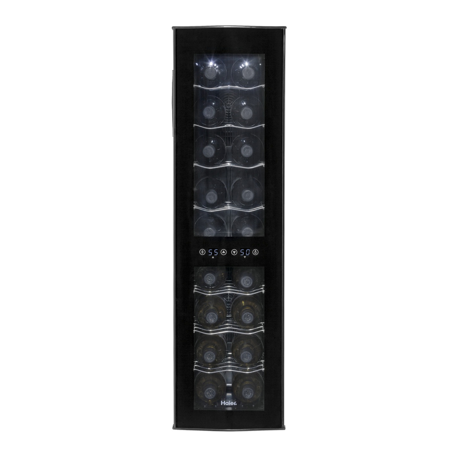
Brief introduction to the cooling system 1. Both the HVW18 series are in-direct cooling single-system wine coolers. 2. A semi-conductor type cooling system is built into the unit. This system is also called “Thermo-electric” cooling system; or “Peltier” system. 3. The core element in the system is a piece of special semi-conductor module. When a direct current passing through this semi-conductor module, one surface of the conductor becomes cold while another surface become hot. - Page 3 PRODUCT MODEL NUMBER INTRODUCTION HVW18ABS / HVW18ABB / HVW18BSS - H = Haier; V = Wine Cellar - Wine Tower - 18 Botles Capacity - Production Series - Black body and black frame - Black body and silver frame - Silver body and silver frame...
- Page 4 Exposed Diagram (Totoal Unit)
- Page 5 Exposed Diagram (Cooling Module)
- Page 6 Circuit Diagam (Total Unit)
- Page 7 Wiring Diagram (Total unit)
-
Page 8: Trouble Shooting
TROUBLE SHOOTING 1. Normal Phenomena – Should not be considered as the trouble of the unit a. Wine cooler does not operate Check if the unit is plugged in. Check if there is power at the power outlet by checking the circuit breaker. Check if the ambient temperature is lower than the unit’s pre-set temperature. - Page 9 For reference only. The model shown in below diagram may vary from actual model.
- Page 10 2. To discover the common trouble in Semi-conductor Wine Cooler Causes for troubles occurring in this type of Wine Cooler are closely related to the quality of components and workmanship in assembling by manufacturers and whether the unit are properly used and maintained.
- Page 11 B. Touching, Listening and Feeling Should be done by qualified technician since it can only be checked during the unit is connected to mains supply. Any of the following points found can tell the unit is in trouble. Abnormal sound is detected (for example, from fans, from PCB); Abnormal temperature inside the cavity is measured (for example, it is not cold;...
- Page 12 b. The sound from PCB. Analysis It seldom happened! It is critical when the sound from PCB is detected. There must be the failure of the component used on the PCB and may cause the safety issue. Remedy Need to replace it immediately. Since it is complicated to check all components on PCB, suggesting to replace it with a new one.
- Page 13 Remedy If yes, fix it. If not, check the fan(s). Fan failure Analysis Detaching the fan wires from the closed-end connector and re-connect it to an independent 12V power supply. If the fan does not work, it is down. Remedy Marking the assembly and the wiring information, detaching the defective fan from the mounting bracket, installing a new fan onto the original position.
- Page 14 D. Always at the lowest temperature level, and it can not be adjusted by the rotary switch Analysis The rotary switch is failure, total current pass through the switch. Dis-connect the rotary switch from the main circuit. To ensure the switch is down, test it with a electronic multi-meter.
- Page 15 d. The Power Supply Unit (PSU) Analysis Check if the aluminium radiator (on the rear housing) is “hot”; or the aluminium radiator inside the cavity is “cold”. If yes, the PSU is normal. If no, check the output of PSU itself by the electronic multi-meter (around 12V should be measured on the output terminal).