D-Link DES-3526 - Switch - Stackable User Manual
Xstack des-3500 series layer 2 managed stackable fast ethernet switch
Hide thumbs
Also See for DES-3526 - Switch - Stackable:
- Command line interface reference manual (246 pages) ,
- User manual (230 pages) ,
- Manual (258 pages)

Related Manuals for D-Link DES-3526 - Switch - Stackable


Summary of Contents for D-Link DES-3526 - Switch - Stackable
-
Page 1: User Manual
® User Manual ® xStack DES-3500 Series Product Model: Layer 2 Managed Stackable Fast Ethernet Switch Release 5.1 ©Copyright 2008. All Rights Reserved... - Page 2 Corporation. Other trademarks and trade names may be used in this document to refer to either the entities claiming the marks and names or their products. D-Link Corporation disclaims any proprietary interest in trademarks and trade names other than its own.
-
Page 3: Table Of Contents
Table of Contents Preface ......................................viii Intended Readers....................................ix Typographical Conventions ................................ix Notes, Notices, and Cautions ................................ix Safety Instructions ....................................x Safety Cautions ....................................x General Precautions for Rack-Mountable Products ........................xi Protecting Against Electrostatic Discharge..........................xii Introduction......................................1 Switch Description .................................. - Page 4 Traps ..........................................19 MIBs ..........................................19 IP Address Assignment ................................20 Connecting Devices to the Switch ............................... 21 Web-based Switch Configuration ..............................22 Introduction......................................22 Login to Web Manager ................................22 Web-based User Interface ................................23 Areas of the User Interface ...................................23 Web Pages....................................
- Page 5 Unicast Forwarding..................................63 Multicast Forwarding ................................... 64 Multicast Port Filtering Mode ..............................65 VLANs....................................... 67 Understanding IEEE 802.1p Priority................................67 VLAN Description ..................................67 ® Notes about VLANs on the xStack DES-3500 Series switches ........................67 IEEE 802.1Q VLANs................................... 67 802.1Q VLAN Tags......................................69 Port VLAN ID.......................................69 Tagging and Untagging....................................70 Ingress Filtering ......................................70...
- Page 6 IP-MAC Binding Port ................................126 IP-MAC Binding Table................................127 IP-MAC Binding Blocked................................128 DHCP Snooping Entries ................................128 IP-MAC Binding Permit IP Pool ............................... 129 Limited IP Multicast Range ................................130 Limited IP Multicast Range Profile Settings..........................130 Limited IP Multicast Range Status Setting ..........................131 Limited IP Multicast Range Setting ............................
- Page 7 Port Capability ......................................164 Initializing Ports for Port Based 802.1x ..............................165 Initializing Ports for MAC Based 802.1x..............................166 Reauthenticate Port(s) for Port Based 802.1x .............................166 Reauthenticate Port(s) for MAC Based 802.1x ............................167 RADIUS Server ..................................167 Guest VLANs..................................... 168 Limitations Using the Guest VLAN................................168 Guest VLAN Configuration ...............................
- Page 8 ARP Spoofing Prevention ................................202 Monitoring ....................................... 204 Port Utilization....................................204 CPU Utilization....................................205 Memory Usage....................................205 Packets ......................................207 Received (RX).................................... 207 UMB Cast (RX) ..................................208 Transmitted (TX) ..................................211 Errors ....................................... 213 Received (RX).................................... 213 Transmitted (TX) ..................................215 Size - Packet Size.....................................
- Page 9 D-Link Single IP Management ................................ 236 Single IP Management (SIM) Overview............................236 The Upgrade to v1.6....................................237 SIM Using the Web Interface ................................238 Topology......................................239 Tool Tips......................................241 Right-Click....................................242 Group Icon ........................................242 Commander Switch Icon.....................................243 Member Switch Icon....................................244 Candidate Switch Icon ....................................245 Menu Bar ....................................
-
Page 10: Preface
® xStack DES-3500 Series Layer 2 Stackable Fast Ethernet Managed Switch User Manual Preface The DES-3500 Series Manual is divided into sections that describe the system installation and operating instructions with examples. Section 1, Introduction - Describes the Switch and its features. Section 2, Installation- Helps you get started with the basic installation of the Switch and also describes the front panel, rear panel, side panels, and LED indicators of the Switch. -
Page 11: Intended Readers
® xStack DES-3500 Series Layer 2 Stackable Fast Ethernet Managed Switch User Manual Intended Readers The DES-3500 Manual contains information for setup and management of the Switch. This manual is intended for network managers familiar with network management concepts and terminology. Typographical Conventions Convention Description... -
Page 12: Safety Instructions
® xStack DES-3500 Series Layer 2 Stackable Fast Ethernet Managed Switch User Manual Safety Instructions Use the following safety guidelines to ensure your own personal safety and to help protect your system from potential damage. Throughout this document, the caution icon ( ) is used to indicate cautions and precautions that you need to review and follow. Safety Cautions To reduce the risk of bodily injury, electrical shock, fire, and damage to the equipment, observe the following precautions. -
Page 13: General Precautions For Rack-Mountable Products
® xStack DES-3500 Series Layer 2 Stackable Fast Ethernet Managed Switch User Manual • Observe extension cable and power strip ratings. Make sure that the total ampere rating of all products plugged into the extension cable or power strip does not exceed 80 percent of the ampere ratings limit for the extension cable or power strip. •... -
Page 14: Protecting Against Electrostatic Discharge
® xStack DES-3500 Series Layer 2 Stackable Fast Ethernet Managed Switch User Manual Protecting Against Electrostatic Discharge Static electricity can harm delicate components inside your system. To prevent static damage, discharge static electricity from your body before you touch any of the electronic components, such as the microprocessor. You can do so by periodically touching an unpainted metal surface on the chassis. -
Page 15: Introduction
Side Panel Description Rear Panel Description Gigabit Combo Ports ® The DES-3500 layer 2 Fast Ethernet switches are members of the D-Link xStack family. Ranging from 10/100Mbps edge ® switches to core gigabit switches, the xStack switch family has been future-proof designed to provide a stacking architecture with fault tolerance, flexibility, port density, robust security and maximum throughput with a user-friendly management interface for the networking professional. -
Page 16: Ports
RS-232 DCE Diagnostic port (console port) for setting up and managing the Switch via a connection to a console terminal or PC using a terminal emulation program. NOTE: For customers interested in D-View, D-Link Corporation's proprietary SNMP management software, go to the D-Link Website (www.dlink.com) and download the software and manual. -
Page 17: Front-Panel Components
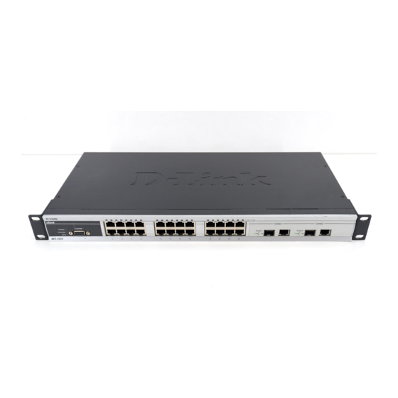
® xStack DES-3500 Series Layer 2 Stackable Fast Ethernet Managed Switch User Manual Front-Panel Components The front panel of the Switch consists of LED indicators for power and for each 10/100 Mbps twisted-pair ports, and two 1000BASE-T Mini-GBIC ports. Figure 1- 1. Front Panel View of the DES-3526 switch Figure 1- 2. -
Page 18: Led Indicators
® xStack DES-3500 Series Layer 2 Stackable Fast Ethernet Managed Switch User Manual LED Indicators The Switch supports LED indicators for Power, Console, RPS (DES-3526/3550) and Port LEDs. The following shows the LED indicators for the DES-3500 Series switches along with an explanation of each indicator. LEDs and there corresponding meanings are displayed below. -
Page 19: Rear Panel Description
® xStack DES-3500 Series Layer 2 Stackable Fast Ethernet Managed Switch User Manual Rear Panel Description The rear panel of the Switch contains an AC power connector. Figure 1- 6. Rear panel view of the DES-3526 Figure 1- 7. Rear panel view of the DES-3550 The AC power connector is a standard three-pronged connector that supports the power cord. -
Page 20: Gigabit Combo Ports
® xStack DES-3500 Series Layer 2 Stackable Fast Ethernet Managed Switch User Manual Figure 1- 10. Side panels of the DES-3550 Gigabit Combo Ports In addition to the 24 (or 48) 10/100 Mbps ports, the Switch features two Gigabit Ethernet Combo ports. These two ports are 1000BASE-T copper ports (provided) and Mini-GBIC ports (optional). - Page 21 ® xStack DES-3500 Series Layer 2 Stackable Fast Ethernet Managed Switch User Manual Figure 1- 13. Installing the Mini-GBIC Module...
-
Page 22: Installation
• RS-232 console cable If any item is found missing or damaged, please contact your local D-Link Reseller for replacement. Before You Connect to the Network The site where you install the Switch may greatly affect its performance. Please follow these guidelines for setting up the Switch. -
Page 23: Installing The Switch Without The Rack
® xStack DES-3500 Series Layer 2 Stackable Fast Ethernet Managed Switch User Manual Installing the Switch without the Rack When installing the Switch on a desktop or shelf, the rubber feet included with the Switch should first be attached. Attach these cushioning feet on the bottom at each corner of the device. -
Page 24: Installing The Switch In A Rack
® xStack DES-3500 Series Layer 2 Stackable Fast Ethernet Managed Switch User Manual Installing the Switch in a Rack The Switch can be mounted in a standard 19" rack. Use the following diagrams to guide you. Figure 2- 3. Fasten mounting brackets to the DES-3526 Figure 2- 4. -
Page 25: Mounting The Switch In A Standard 19" Rack
® xStack DES-3500 Series Layer 2 Stackable Fast Ethernet Managed Switch User Manual Mounting the Switch in a Standard 19" Rack CAUTION: Installing systems in a rack without the front and side stabilizers installed could cause the rack to tip over, potentially resulting in bodily injury under certain circumstances. Therefore, always install the stabilizers before installing components in the rack. -
Page 26: Power On (Ac Power)
® xStack DES-3500 Series Layer 2 Stackable Fast Ethernet Managed Switch User Manual Power On (AC Power) Plug one end of the AC power cord into the power connector of the Switch and the other end into the local power source outlet. After the Switch is powered on, the LED indicators will momentarily blink. -
Page 27: Connecting The Switch
® xStack DES-3500 Series Layer 2 Stackable Fast Ethernet Managed Switch User Manual Section 3 Connecting the Switch Switch to End Node Switch to Hub or Switch Connecting To Network Backbone or Server NOTE: All 24 (48 for the DES-3550) high-performance NWay Ethernet ports can support both MDI-II and MDI-X connections. -
Page 28: Switch To Hub Or Switch
® xStack DES-3500 Series Layer 2 Stackable Fast Ethernet Managed Switch User Manual Switch to Hub or Switch These connections can be accomplished in a number of ways using a normal cable. • A 10BASE-T hub or switch can be connected to the Switch via a twisted-pair Category 3, 4 or 5 UTP/STP cable. •... -
Page 29: Connecting To Network Backbone Or Server
® xStack DES-3500 Series Layer 2 Stackable Fast Ethernet Managed Switch User Manual Connecting To Network Backbone or Server The two Mini-GBIC combo ports are ideal for unlinking to a network backbone or server. The copper ports operate at a speed of 1000, 100 or 10Mbps in full or half duplex mode. -
Page 30: Introduction To Switch Management
® xStack DES-3500 Series Layer 2 Stackable Fast Ethernet Managed Switch User Manual Section 4 Introduction to Switch Management Management Options Web-based Management Interface SNMP-Based Management Managing User Accounts Command Line Console Interface through the Serial Port Connecting the Console Port (RS-232 DCE) First Time Connecting to the Switch Password Protection SNMP Settings... - Page 31 ® xStack DES-3500 Series Layer 2 Stackable Fast Ethernet Managed Switch User Manual To connect a terminal to the console port: 1. Connect the female connector of the RS-232 cable directly to the console port on the Switch, and tighten the captive retaining screws.
-
Page 32: First Time Connecting To The Switch
® xStack DES-3500 Series Layer 2 Stackable Fast Ethernet Managed Switch User Manual First Time Connecting to the Switch The Switch supports user-based security that can allow you to prevent unauthorized users from accessing the Switch or changing its settings. This section tells how to log onto the Switch. NOTE: The passwords used to access the Switch are case-sensitive;... - Page 33 NOTICE: In case of lost passwords or password corruption, please refer to the D-Link website and the White Paper entitled “Password Recovery Procedure”, which will guide you through the steps necessary to resolve this issue.
-
Page 34: Snmp Settings
® xStack DES-3500 Series Layer 2 Stackable Fast Ethernet Managed Switch User Manual SNMP Settings Simple Network Management Protocol (SNMP) is an OSI Layer 7 (Application Layer) designed specifically for managing and monitoring network devices. SNMP enables network management stations to read and modify the settings of gateways, routers, switches, and other network devices. -
Page 35: Ip Address Assignment
Switch's Telnet or Web-based management agent. NOTICE: In case of lost passwords or password corruption, please refer to the D-Link website and the White Paper entitled “Password Recovery Procedure”, which will guide you through the steps necessary to resolve this issue. -
Page 36: Connecting Devices To The Switch
® xStack DES-3500 Series Layer 2 Stackable Fast Ethernet Managed Switch User Manual Figure 4- 5. Assigning the Switch an IP Address In the above example, the Switch was assigned an IP address of 10.41.44.254 with a subnet mask of 255.0.0.0. The system message Success indicates that the command was executed successfully. -
Page 37: Web-Based Switch Configuration
® xStack DES-3500 Series Layer 2 Stackable Fast Ethernet Managed Switch User Manual Section 5 Web-based Switch Configuration Introduction Login to Web manager Web-Based User Interface Basic Setup Reboot Basic Switch Setup Network Management Switch Utilities Network Monitoring IGMP Snooping Status Introduction All software functions of the DES-3500 Series switches can be managed, configured and monitored via the embedded web-based (HTML) interface. -
Page 38: Web-Based User Interface
Area 1 Select the menu or window to be displayed. The folder icons can be opened to display the hyper- linked menu buttons and subfolders contained within them. Click the D-Link logo to go to the D-Link website. Area 2 Presents a graphical near real-time image of the front panel of the Switch. -
Page 39: Web Pages
Switch to the greater network. NOTICE: In case of lost passwords or password corruption, please refer to the D-Link website and the White Paper entitled “Password Recovery Procedure”, which will guide you through the steps necessary to resolve this issue. -
Page 40: Configuring The Switch
® xStack DES-3500 Series Layer 2 Stackable Fast Ethernet Managed Switch User Manual Section 6 Configuring the Switch Switch Information IP Address Advanced Settings Port Configuration Port Description Port Mirroring Link Aggregation LACP Port Setting MAC Notification IGMP Spanning Tree Forward Filtering VLANs Traffic Control... -
Page 41: Switch Information
® xStack DES-3500 Series Layer 2 Stackable Fast Ethernet Managed Switch User Manual Switch Information The subsections below describe how to change some of the basic settings for the Switch such as changing IP settings and assigning user names and passwords for management access privileges, as well as how to save the changes and restart the Switch. Click, Configuration >... - Page 42 ® xStack DES-3500 Series Layer 2 Stackable Fast Ethernet Managed Switch User Manual Figure 6- 2. IP Address Settings window To manually assign the Switch's IP address, subnet mask, and default gateway address: 1. Select Manual from the Get IP From drop-down menu. 2.
- Page 43 ® xStack DES-3500 Series Layer 2 Stackable Fast Ethernet Managed Switch User Manual 255.255.255.0 for a Class C network, but custom subnet masks are allowed. Default IP address that determines where packets with a destination address outside the current subnet Gateway should be sent.
- Page 44 DES-3500 Series Layer 2 Stackable Fast Ethernet Managed Switch User Manual NOTICE: In case of lost passwords or password corruption, please refer to the D-Link website and the White Paper entitled “Password Recovery Procedure”, which will guide you through the steps necessary to resolve this issue.
-
Page 45: Advanced Settings
® xStack DES-3500 Series Layer 2 Stackable Fast Ethernet Managed Switch User Manual Advanced Settings The Switch Information (Advanced Settings) window contains the main settings for all major functions for the Switch. To view this window click, Configuration > Advanced Settings. Figure 6- 3. - Page 46 ® xStack DES-3500 Series Layer 2 Stackable Fast Ethernet Managed Switch User Manual The "well-known" TCP port for the Web interface is 80. Number Link Aggregation The algorithm that the Switch uses to balance the load across the ports that make up the Algorithm port trunk group is defined by this definition.
-
Page 47: Port Configuration
® xStack DES-3500 Series Layer 2 Stackable Fast Ethernet Managed Switch User Manual Port Configuration This section contains information for configuring various attributes and properties for individual physical ports and Err-disabled Ports, including port speed and flow control. To display the following window click, Configuration > Port Configuration. Figure 6- 4. - Page 48 ® xStack DES-3500 Series Layer 2 Stackable Fast Ethernet Managed Switch User Manual between Auto, Normal or Cross. Auto will automatically switch to the proper configuration once a cable is connected. Normal will be selected if a straight-through cable is being used and Cross should be selected if a crossover cable is being used.
-
Page 49: Port Description
® xStack DES-3500 Series Layer 2 Stackable Fast Ethernet Managed Switch User Manual Port Description The DES-3500 Series switches support a port description feature where the user may name various ports on the Switch. To assign names to various ports, click Configuration > Port Description: Figure 6- 5. -
Page 50: Port Mirroring
® xStack DES-3500 Series Layer 2 Stackable Fast Ethernet Managed Switch User Manual Port Mirroring The Switch allows you to copy frames transmitted and received on a port and redirect the copies to another port. You can attach a monitoring device to the mirrored port, such as a sniffer or an RMON probe, to view details about the packets passing through the first port. -
Page 51: Link Aggregation
® xStack DES-3500 Series Layer 2 Stackable Fast Ethernet Managed Switch User Manual Link Aggregation Understanding Port Trunk Groups Port trunk groups are used to combine a number of ports together to make a single high-bandwidth data pipeline. The DES-3500 Series switches support up to six port trunk groups with 2 to 8 ports in each group. A potential bit rate of 8000 Mbps can be achieved. - Page 52 ® xStack DES-3500 Series Layer 2 Stackable Fast Ethernet Managed Switch User Manual The Switch treats all ports in a trunk group as a single port. Data transmitted to a specific host (destination address) will always be transmitted over the same port in a trunk group. This allows packets in a data stream to arrive in the same order they were sent. NOTE: If any ports within the trunk group become disconnected, packets intended for the discon- nected port will be load shared among the other unlinked ports of the link aggregation group.
- Page 53 ® xStack DES-3500 Series Layer 2 Stackable Fast Ethernet Managed Switch User Manual Figure 6- 10. Link Aggregation Settings window - Modify The user-changeable parameters are as follows: Parameter Description Group ID Select an ID number for the group, between 1 and 6. State Trunk groups can be toggled between Enabled and Disabled.
-
Page 54: Lacp Port Setting
® xStack DES-3500 Series Layer 2 Stackable Fast Ethernet Managed Switch User Manual LACP Port Setting The LACP Port Setting window is used in conjunction with the Link Aggregation window to create port trunking groups on the Switch. Using the following window, the user may set which ports will be active and passive in processing and sending LACP control frames. -
Page 55: Mac Notification
® xStack DES-3500 Series Layer 2 Stackable Fast Ethernet Managed Switch User Manual dynamically, one end of the connection must have "active" LACP ports (see above). After setting the previous parameters, click Apply to allow your changes to be implemented. The LACP Port Table shows which ports are active and/or passive. -
Page 56: Mac Notification Port Settings
® xStack DES-3500 Series Layer 2 Stackable Fast Ethernet Managed Switch User Manual MAC Notification Port Settings To change MAC notification settings for a port or group of ports on the Switch, click Configuration > MAC Notification > MAC Notification Port Settings, which will display the following window: Figure 6- 13. -
Page 57: Igmp
® xStack DES-3500 Series Layer 2 Stackable Fast Ethernet Managed Switch User Manual IGMP Internet Group Management Protocol (IGMP) snooping allows the Switch to recognize IGMP queries and reports sent between network stations or devices and an IGMP host. When enabled for IGMP snooping, the Switch can open or close a port to a specific device based on IGMP messages passing through the Switch. - Page 58 ® xStack DES-3500 Series Layer 2 Stackable Fast Ethernet Managed Switch User Manual The following parameters may be viewed or modified: Parameter Description VLAN ID This is the VLAN ID that, along with the VLAN Name, identifies the VLAN the user wishes to modify the IGMP Snooping Settings for.
-
Page 59: Static Router Ports Entry
® xStack DES-3500 Series Layer 2 Stackable Fast Ethernet Managed Switch User Manual Static Router Ports Entry A static router port is a port that has a multicast router attached to it. Generally, this router would have a connection to a WAN or to the Internet. -
Page 60: Forbidden Router Ports Entry
® xStack DES-3500 Series Layer 2 Stackable Fast Ethernet Managed Switch User Manual Forbidden Router Ports Entry The Forbidden Router Ports Entry section will allow users to set a port or group of ports belonging to a VLAN as being forbidden from receiving information from or being connected to multicast routers. -
Page 61: Igmp Multicast Vlan
® xStack DES-3500 Series Layer 2 Stackable Fast Ethernet Managed Switch User Manual IGMP Multicast VLAN Standard Internet Group Management Protocol (IGMP) snooping purposely limits multicast traffic so that only the interfaces actively associating with the multicast are flooded. A layer 2 switch will snoop IGMP packet traffic between a multicast router and host devices to learn and record the associated multicast groups and their member ports. - Page 62 ® xStack DES-3500 Series Layer 2 Stackable Fast Ethernet Managed Switch User Manual The following parameters can be set: Parameter Description The VLAN ID of the multicast VLAN to be created. The user may choose a number between 1-4094 to identify this VLAN. Up to 3 multicast VLANs can be configured. VLAN Name The name of the multicast VLAN to be configured.
- Page 63 ® xStack DES-3500 Series Layer 2 Stackable Fast Ethernet Managed Switch User Manual Source Port A port on the Switch to be designated as the source port for multicast traffic. Multicast traffic entering the switch will be forwarded from this port to member ports on the same VLAN. Note that the Source port must be different from the member ports of the created VLAN.
-
Page 64: Spanning Tree
STP will be familiar to most networking professionals. However, since 802.1w RSTP and 802.1s MSTP has been recently introduced to D-Link managed Ethernet switches, a brief introduction to the technology is provided below followed by a description of how to set up 802.1d STP, 802.1w RSTP and 802.1s MSTP. -
Page 65: Edge Port
® xStack DES-3500 Series Layer 2 Stackable Fast Ethernet Managed Switch User Manual 802.1d MSTP 802.1w RSTP 802.1d STP Forwarding Learning Discarding Discarding Disabled Discarding Discarding Blocking Discarding Discarding Listening Learning Learning Learning Forwarding Forwarding Forwarding Table 6- 1. Comparing Port States RSTP is capable of a more rapid transition to a forwarding state - it no longer relies on timer configurations - RSTP compliant bridges are sensitive to feedback from other RSTP compliant bridge links. -
Page 66: Stp Bridge Global Settings
® xStack DES-3500 Series Layer 2 Stackable Fast Ethernet Managed Switch User Manual STP Bridge Global Settings To view the STP Bridge Global Settings, click Configuration > Spanning Tree > STP Bridge Global Settings. Figure 6- 23. STP Bridge Global Settings window - STP... - Page 67 ® xStack DES-3500 Series Layer 2 Stackable Fast Ethernet Managed Switch User Manual Figure 6- 24. STP Bridge Global Settings window - RSTP (default) Figure 6- 25. STP Bridge Global Settings window - MSTP...
- Page 68 ® xStack DES-3500 Series Layer 2 Stackable Fast Ethernet Managed Switch User Manual NOTE: The Hello Time cannot be longer than the Max. Age. Otherwise, a configuration error will occur. Observe the following formulas when setting the above parameters: Max. Age ≤ 2 x (Forward Delay - 1 second) Max.
-
Page 69: Mst Configuration Table
® xStack DES-3500 Series Layer 2 Stackable Fast Ethernet Managed Switch User Manual MST Configuration Table The following screens in the MST Configuration Table window allow the user to configure a MSTI instance on the Switch. These settings will uniquely identify a multiple spanning tree instance set on the Switch. The Switch initially possesses one CIST or Common Internal Spanning Tree of which the user may modify the parameters for but cannot change the MSTI ID for, and cannot be deleted. - Page 70 ® xStack DES-3500 Series Layer 2 Stackable Fast Ethernet Managed Switch User Manual VID List (1-4094) This field is used to specify the VID range from configured VLANs set on the Switch. Supported VIDs on the Switch range from ID number 1 to 4094. Priority (0-61440) Select a value between 0 and 61440 to specify the priority for a specified MSTI for forwarding packets.
-
Page 71: Msti Settings
® xStack DES-3500 Series Layer 2 Stackable Fast Ethernet Managed Switch User Manual Type This field allows the user to choose a desired method for altering the MSTI settings. The user has four choices. Add - Select this parameter to add VIDs to the MSTI ID, in conjunction with the VID List •... -
Page 72: Stp Instance Settings
® xStack DES-3500 Series Layer 2 Stackable Fast Ethernet Managed Switch User Manual Parameter Description Instance ID Displays the MSTI ID of the instance being configured. An entry of 0 in this field denotes the CIST (default MSTI). This parameter is set to represent the relative cost of forwarding packets to specified ports Internal cost (0=Auto) when an interface is selected within a STP instance. - Page 73 ® xStack DES-3500 Series Layer 2 Stackable Fast Ethernet Managed Switch User Manual Figure 6- 33. STP Instance Operational Status...
-
Page 74: Mstp Port Information
® xStack DES-3500 Series Layer 2 Stackable Fast Ethernet Managed Switch User Manual MSTP Port Information STP can be set up on a port per port basis. To view the following window click Configuration > Spanning Tree > MSTP Port Information: Figure 6- 34. - Page 75 ® xStack DES-3500 Series Layer 2 Stackable Fast Ethernet Managed Switch User Manual NOTE: If you want to enable Forwarding BPDU on a per port basis, the following settings must first be in effect: 1. STP must be globally disabled and 2. Forwarding BPDU must be globally enabled. These are the default settings configurable in the STP Bridge Global Settings menu discussed previously.
- Page 76 ® xStack DES-3500 Series Layer 2 Stackable Fast Ethernet Managed Switch User Manual is globally enabled (See STP Bridge Global Settings above). hw_filtering is an option that is only required by some legacy chipsets, which cannot support per L2 protocol packet control. When the state is set to hw_filtering, if STP BPDU is received by this port, the port will be changed to BPDU hardware filtering mode such that all layer 2 control packets will be dropped by the hardware.
-
Page 77: Loopback Detection
® xStack DES-3500 Series Layer 2 Stackable Fast Ethernet Managed Switch User Manual Loopback Detection This feature is used to temporarily shutdown a port on the Switch when a CTP (Configuration Testing Protocol) packet has been looped back to the switch. When the Switch detects CTP packets are received from a port or a VLAN, it signifies a loop on the network. -
Page 78: Forwarding Filtering
® xStack DES-3500 Series Layer 2 Stackable Fast Ethernet Managed Switch User Manual The following parameters can be set: Parameter Description Loopback Detection Global Settings Loopback Use the pull-down menu to enable or disable Loopback Detection globally on the Switch. The Detection Status default is Disabled. -
Page 79: Multicast Forwarding
® xStack DES-3500 Series Layer 2 Stackable Fast Ethernet Managed Switch User Manual Multicast Forwarding The following figure and table describe how to set up Multicast Forwarding on the Switch. To view this window click, Configuration > Forwarding Filtering > Multicast Forwarding: Figure 6- 37. -
Page 80: Multicast Port Filtering Mode
® xStack DES-3500 Series Layer 2 Stackable Fast Ethernet Managed Switch User Manual Multicast Port Filtering Mode The following figure and table describe how to set up multicast forwarding on the Switch. To view this window click, Configuration > Forwarding Filtering > Multicast Port Filtering Mode Setup. Figure 6- 39. - Page 81 ® xStack DES-3500 Series Layer 2 Stackable Fast Ethernet Managed Switch User Manual Forward All Groups - This will instruct the Switch to forward a multicast packet to all • multicast groups residing within the range of ports specified above. Forward Unregistered Groups - This will instruct the Switch to forward a multicast •...
-
Page 82: Vlans
® xStack DES-3500 Series Layer 2 Stackable Fast Ethernet Managed Switch User Manual VLANs Understanding IEEE 802.1p Priority Priority tagging is a function defined by the IEEE 802.1p standard designed to provide a means of managing traffic on a network where many different types of data may be transmitted simultaneously. - Page 83 ® xStack DES-3500 Series Layer 2 Stackable Fast Ethernet Managed Switch User Manual IEEE 802.1Q (tagged) VLANs are implemented on the Switch. 802.1Q VLANs require tagging, which enables them to span the entire network (assuming all switches on the network are IEEE 802.1Q-compliant). VLANs allow a network to be segmented in order to reduce the size of broadcast domains.
-
Page 84: 802.1Q Vlan Tags
® xStack DES-3500 Series Layer 2 Stackable Fast Ethernet Managed Switch User Manual 802.1Q VLAN Tags The figure below shows the 802.1Q VLAN tag. There are four additional octets inserted after the source MAC address. Their presence is indicated by a value of 0x8100 in the EtherType field. When a packet's EtherType field is equal to 0x8100, the packet carries the IEEE 802.1Q/802.1p tag. -
Page 85: Tagging And Untagging
® xStack DES-3500 Series Layer 2 Stackable Fast Ethernet Managed Switch User Manual Unfortunately, not all network devices are 802.1Q compliant. These devices are referred to as tag-unaware. 802.1Q devices are referred to as tag-aware. Prior to the adoption of 802.1Q VLANs, port-based and MAC-based VLANs were in common use. These VLANs relied upon a Port VLAN ID (PVID) to forward packets. -
Page 86: Port-Based Vlans
® xStack DES-3500 Series Layer 2 Stackable Fast Ethernet Managed Switch User Manual NOTE: If no VLANs are configured on the Switch, then all packets will be forwarded to any desti- nation port. Packets with unknown source addresses will be flooded to all ports. Broadcast and multicast packets will also be flooded to all ports. -
Page 87: Asymmetric Vlans
® xStack DES-3500 Series Layer 2 Stackable Fast Ethernet Managed Switch User Manual Asymmetric VLANs ® The xStack DES-3500 Switch Series has the capability to create and utilize Asymmetric VLANs on the Switch. Asymmetric VLANs allow devices to transmit packets on one VLAN and receive it on another VLAN. This configuration is accomplished through the use of three functions: enabling Asymmetric VLANs, VLAN creation, and GVRP configuration. -
Page 88: Vlan And Trunk Groups
® xStack DES-3500 Series Layer 2 Stackable Fast Ethernet Managed Switch User Manual VLAN and Trunk Groups The members of a trunk group have the same VLAN setting. Any VLAN setting on the members of a trunk group will apply to the other member ports. - Page 89 ® xStack DES-3500 Series Layer 2 Stackable Fast Ethernet Managed Switch User Manual Figure 6- 45. 802.1Q Static VLAN window - Add To return to the Current 802.1Q Static VLANs Entries window, click the Show All Static VLAN Entries link. To change an existing 802.1Q VLAN entry, click the Modify button of the corresponding entry you wish to modify.
- Page 90 ® xStack DES-3500 Series Layer 2 Stackable Fast Ethernet Managed Switch User Manual NOTE: The Switch supports up to 255 static VLAN entries. Figure 6- 47. 802.1Q Static VLAN window - Modify The following fields can then be set in either the Add or Modify 802.1Q Static VLANs windows: Parameter Description VID (VLAN ID)
-
Page 91: Gvrp Setting
® xStack DES-3500 Series Layer 2 Stackable Fast Ethernet Managed Switch User Manual GVRP Setting The 802.1Q Port Settings window, shown below, allows you to determine whether the Switch will share its VLAN configuration information with other GARP VLAN Registration Protocol (GVRP) enabled switches. -
Page 92: Traffic Control
® xStack DES-3500 Series Layer 2 Stackable Fast Ethernet Managed Switch User Manual Click Apply to implement changes made. Traffic Control On a computer network, packets such as Multicast packets and Broadcast packets continually flood the network as normal procedure. At times, this traffic may increase do to a malicious endstation on the network or a malfunctioning device, such as a faulty network card. - Page 93 ® xStack DES-3500 Series Layer 2 Stackable Fast Ethernet Managed Switch User Manual Figure 6- 49. Traffic Control Setting window...
- Page 94 ® xStack DES-3500 Series Layer 2 Stackable Fast Ethernet Managed Switch User Manual Use the Traffic Control Setting window to enable or disable storm control and adjust the threshold for multicast and broadcast storms, as well as Unicast (Destination Look Up Failure). Traffic control settings are applied to individual Switch modules. To view the following window, click Configuration >...
- Page 95 ® xStack DES-3500 Series Layer 2 Stackable Fast Ethernet Managed Switch User Manual NOTE: Ports that are in the Shutdown forever mode will be seen as Discarding in Spanning Tree windows and implementations though these ports will still be forwarding BPDUs to the Switch’s CPU. NOTE: Ports that are in Shutdown Forever mode will be seen as link down in all windows and screens until the user recovers these ports or waits for 5 mins to let the Shutdown Forever mode enter Auto- Recovery.
-
Page 96: Port Security
® xStack DES-3500 Series Layer 2 Stackable Fast Ethernet Managed Switch User Manual Port Security A given port's (or a range of ports') dynamic MAC address learning can be locked such that the current source MAC addresses entered into the MAC address forwarding table can not be changed once the port lock is enabled. -
Page 97: Qos
® xStack DES-3500 Series Layer 2 Stackable Fast Ethernet Managed Switch User Manual The DES-3500 Series switches supports 802.1p priority queuing Quality of Service. The following section discusses the implementation of QoS (Quality of Service) and benefits of using 802.1p priority queuing. Advantages of QoS QoS is an implementation of the IEEE 802.1p standard that allows network administrators a method of reserving bandwidth for important functions that require a large bandwidth or have a high priority, such as VoIP (voice-over Internet Protocol), web... -
Page 98: Understanding Qos
® xStack DES-3500 Series Layer 2 Stackable Fast Ethernet Managed Switch User Manual Understanding QoS The Switch has four priority queues. These priority queues are labeled as 3, the high queue to 0, the lowest queue. The eight priority tags, specified in IEEE 802.1p are mapped to the Switch's priority tags as follows: •... -
Page 99: Port Bandwidth
® xStack DES-3500 Series Layer 2 Stackable Fast Ethernet Managed Switch User Manual Port Bandwidth The bandwidth control settings are used to place a ceiling on the transmitting and receiving data rates for any selected port. Click Configuration > QoS > Port Bandwidth, to view the window shown below. Figure 6- 52. -
Page 100: Scheduling
® xStack DES-3500 Series Layer 2 Stackable Fast Ethernet Managed Switch User Manual receiving and transmitting packets. No Limit This drop-down menu allows you to specify that the selected port will have no bandwidth limit. Enabled disables the limit. Rate This field allows you to enter the data rate, in Mbit/s, that will be the limit for the selected port. -
Page 101: 802.1P Default Priority
® xStack DES-3500 Series Layer 2 Stackable Fast Ethernet Managed Switch User Manual 802.1p Default Priority The Switch allows the assignment of a default 802.1p priority to each port on the Switch. This window allows you to assign a default 802.1p priority to any given port on the Switch. -
Page 102: Traffic Segmentation
® xStack DES-3500 Series Layer 2 Stackable Fast Ethernet Managed Switch User Manual Traffic Segmentation Traffic segmentation is used to limit traffic flow from a single port to a group of ports on either a single switch (in standalone mode) or a group of ports on another switch in a switch stack (Single IP). This method of segmenting the flow of traffic is similar to using VLANs to limit traffic, but is more restrictive. -
Page 103: System Severity Alerts
® xStack DES-3500 Series Layer 2 Stackable Fast Ethernet Managed Switch User Manual System Severity Alerts The Switch can be configured to allow alerts be logged or sent as a trap to an SNMP agent or both. The level at which the alert triggers either a log entry or a trap message can be set as well. - Page 104 ® xStack DES-3500 Series Layer 2 Stackable Fast Ethernet Managed Switch User Manual Figure 6- 59. System Log Server window – Add The following parameters can be set: Parameter Description Index Syslog server settings index (1-4). Server IP The IP address of the Syslog server. Severity This drop-down menu allows you to select the level of messages that will be sent.
-
Page 105: Sntp Settings
® xStack DES-3500 Series Layer 2 Stackable Fast Ethernet Managed Switch User Manual kernel messages user-level messages mail system system daemons security/authorization messages messages generated internally by syslog line printer subsystem network news subsystem UUCP subsystem clock daemon security/authorization messages FTP daemon NTP subsystem log audit... -
Page 106: Time Zone And Dst
® xStack DES-3500 Series Layer 2 Stackable Fast Ethernet Managed Switch User Manual Figure 6- 60. Current Time: Status window The following parameters can be set or are displayed: Parameter Description Current Time: Status The current local date and time for the system. Current Time Time Source Displays the time source for the system. - Page 107 ® xStack DES-3500 Series Layer 2 Stackable Fast Ethernet Managed Switch User Manual Figure 6- 61. Time Zone and DST Settings window The following parameters can be set: Parameter Description Time Zone and DST Settings Use this pull-down menu set the DST Settings as disabled, repeating, or annual. Daylight Saving Time State Daylight Saving...
-
Page 108: Acl
® xStack DES-3500 Series Layer 2 Stackable Fast Ethernet Managed Switch User Manual HH:MM To: Which Day Enter the week of the month the DST will end. To: Day of Week Enter the day of the week that DST will end. To: Month Enter the month that DST will end. - Page 109 ® xStack DES-3500 Series Layer 2 Stackable Fast Ethernet Managed Switch User Manual Figure 6- 62. Access Profile Table window All free ACL rules will be listed in the Free ACL Rules Table as above. To add an entry to the Access Profile Table, click the Add button.
- Page 110 ® xStack DES-3500 Series Layer 2 Stackable Fast Ethernet Managed Switch User Manual a limit to the total number of profiles that can be created. Type Select profile based on Ethernet (MAC Address), IP address or packet content mask. This will change the menu according to the requirements for the type of profile.
- Page 111 ® xStack DES-3500 Series Layer 2 Stackable Fast Ethernet Managed Switch User Manual Figure 6- 64. Access Profile Configuration window (IP) The following parameters can be set, for IP: Parameter Description Profile ID (1-255) Type in a unique identifier number for this profile set. The number is used to set the relative priority for the profile.
- Page 112 ® xStack DES-3500 Series Layer 2 Stackable Fast Ethernet Managed Switch User Manual VLAN Selecting this option instructs the Switch to examine the VLAN part of each packet header and use this as the, or part of the criterion for forwarding. Source IP Mask Enter an IP address mask for the source IP address.
- Page 113 ® xStack DES-3500 Series Layer 2 Stackable Fast Ethernet Managed Switch User Manual Figure 6- 65. Access Profile Configuration window (Packet Content Mask) This screen will aid the user in Switch to mask packet headers beginning with the offset value specified. The following fields are used to configure the Packet Content Mask: Parameter Description...
- Page 114 ® xStack DES-3500 Series Layer 2 Stackable Fast Ethernet Managed Switch User Manual packet to the 16th byte. value (16-31) – Enter a value in hex form to mask the packet from byte 16 to byte 31. • value (32-47) – Enter a value in hex form to mask the packet from byte 32 to byte 47. •...
- Page 115 ® xStack DES-3500 Series Layer 2 Stackable Fast Ethernet Managed Switch User Manual Figure 6- 68. Access Rule Configuration window (IP) Configure the following Access Rule Configuration settings: Parameter Description Profile ID This is the identifier number for this profile set. Mode Select Permit to specify that the Switch, according to any additional rule, forward the packets that match the access profile added (see below).
- Page 116 ® xStack DES-3500 Series Layer 2 Stackable Fast Ethernet Managed Switch User Manual Replace DSCP (0-63) Select this option to instruct the Switch to replace the DSCP value (in a packet that meets the selected criteria) with the value entered in the adjacent field. VLAN Name Allows the entry of a name for a previously configured VLAN.
- Page 117 ® xStack DES-3500 Series Layer 2 Stackable Fast Ethernet Managed Switch User Manual Figure 6- 70. Access Rule Table To configure the ACL Flow Meter settings click the Configure button under the Flow Meter heading of the Access Rule Table. These settings are used to limit the bandwidth of the ingress traffic on the Switch.
-
Page 118: Parameters Description
® xStack DES-3500 Series Layer 2 Stackable Fast Ethernet Managed Switch User Manual To configure the Access Rule for Ethernet, open the Access Profile Table and click Modify for an Ethernet entry. This will open the following window: Figure 6- 73. Access Rule Table window (Ethernet) The user may search for the settings of a particular Access ID by entering that ID into the Access ID field above and clicking Find. - Page 119 ® xStack DES-3500 Series Layer 2 Stackable Fast Ethernet Managed Switch User Manual Select Deny to specify that packets that match the access profile are not forwarded by the Switch and will be filtered. Access ID Type in a unique identifier number for this access. This value can be set from 1 - 65535. Auto Assign –...
- Page 120 ® xStack DES-3500 Series Layer 2 Stackable Fast Ethernet Managed Switch User Manual Figure 6- 75. Access Rule Display window (Ethernet) To return to the Access Rule Table, click the hyperlinked Show All Access Rule Entries. Figure 6- 76. Access Rule Table To configure the ACL Flow Meter settings click the Configure button under the Flow Meter heading of the Access Rule Table.
- Page 121 ® xStack DES-3500 Series Layer 2 Stackable Fast Ethernet Managed Switch User Manual Figure 6- 77 ACL Meter Setting window (Configuration) To return to the Access Rule Entry Table click the hyperlinked Show All Access Rule Entries. To view the Flow Metering Entries click the hyperlinked Show All Flow Metering Entries the following window will be displayed.
- Page 122 ® xStack DES-3500 Series Layer 2 Stackable Fast Ethernet Managed Switch User Manual To remove a previously created rule, select it and click the button. Access rules are indexed using the Access ID number. To locate a specific Access Rule in the table, enter the Access ID and click Find. To display all rules in the table, click the View All Entries button.
- Page 123 ® xStack DES-3500 Series Layer 2 Stackable Fast Ethernet Managed Switch User Manual Mode Select Permit to specify that the Switch, according to any additional rule, forwards the packets that match the access profile added (see below). Select Deny to specify the packets that match the access profile are not forwarded by the Switch and will be filtered.
- Page 124 ® xStack DES-3500 Series Layer 2 Stackable Fast Ethernet Managed Switch User Manual Figure 6- 81. Access Rule Display window (Packet Content) To return to the Access Rule Table, click the hyperlinked Show All Access Rule Entries.
- Page 125 ® xStack DES-3500 Series Layer 2 Stackable Fast Ethernet Managed Switch User Manual Figure 6- 82. Access Rule Table To configure the ACL Flow Meter settings click the Configure button under the Flow Meter heading of the Access Rule Table. These settings are used to limit the bandwidth of the ingress traffic on the Switch.
-
Page 126: Acl Flow Meter
(MAC Address). However, ARP is vulnerable as it can be easily spoofed and utilized to attack a LAN. For a more detailed explanation on how ARP works and how to employ D-Link’s advanced unique Packet Content ACL to prevent ARP spoofing attack, please see... -
Page 127: Cpu Interface Filtering
® xStack DES-3500 Series Layer 2 Stackable Fast Ethernet Managed Switch User Manual CPU Interface Filtering ® Due to a chipset limitation and the need for extra switch security, the xStack DES-3500 Series switches incorporate CPU Interface filtering. This added feature increases the running security of the Switch by enabling the user to create a list of access rules for packets destined for the Switch’s CPU interface. - Page 128 ® xStack DES-3500 Series Layer 2 Stackable Fast Ethernet Managed Switch User Manual Figure 6- 88. CPU Interface Filtering Profile Configuration window for Ethernet The following fields may be modified: Parameter Description Profile ID (1-5) Type in a unique identifier number for this profile set. This value can be set from 1 - 5. Type Select profile based on Ethernet (MAC Address), IP address or packet content mask.
- Page 129 ® xStack DES-3500 Series Layer 2 Stackable Fast Ethernet Managed Switch User Manual The page shown below is the CPU Interface Filtering Profile Configuration for IP page. Figure 6- 89. CPU Interface Filtering Profile Configuration window for IP The following parameters can be modified: Parameter Description Profile ID (1-5)
- Page 130 ® xStack DES-3500 Series Layer 2 Stackable Fast Ethernet Managed Switch User Manual Source IP Mask Enter an IP address mask for the source IP address. Destination IP Mask Enter an IP address mask for the destination IP address. DSCP Selecting this option instructs the Switch to examine the DiffServ Code part of each packet header and use this as the, or part of the criterion for forwarding.
- Page 131 ® xStack DES-3500 Series Layer 2 Stackable Fast Ethernet Managed Switch User Manual Figure 6- 90. CPU Interface Filtering Profile Configuration window for Packet Content Mask This screen will aid the user in configuring the Switch to mask packet headers beginning with the offset value specified. The following fields are used to configure the Packet Content Mask: Parameter Description...
- Page 132 ® xStack DES-3500 Series Layer 2 Stackable Fast Ethernet Managed Switch User Manual packet to the 15th byte. value (16-31) – Enter a value in hex form to mask the packet from byte 16 to byte 31. • value (32-47) – Enter a value in hex form to mask the packet from byte 32 to byte 47. •...
- Page 133 ® xStack DES-3500 Series Layer 2 Stackable Fast Ethernet Managed Switch User Manual Figure 6- 93. CPU Interface filtering rule Configuration window for Ethernet To set the CPU Access Rule for Ethernet, adjust the following parameters and click Apply. Parameters Description Profile ID This is the identifier number for this profile set.
- Page 134 ® xStack DES-3500 Series Layer 2 Stackable Fast Ethernet Managed Switch User Manual To view the settings of a previously configured rule, click in the CPU Interface Filtering Rule Table to view the following screen: Figure 6- 94. CPU Interface Filtering Rule Display for Ethernet The following window is the CPU Interface Filtering Rule Configuration for IP.
- Page 135 ® xStack DES-3500 Series Layer 2 Stackable Fast Ethernet Managed Switch User Manual Configure the following CPU Interface Filtering Rule Configuration settings for IP: Parameter Description Profile ID This is the identifier number for this profile set. Select Permit to specify that the packets that match the access profile are forwarded by the Mode Switch, according to any additional rule added (see below).
- Page 136 ® xStack DES-3500 Series Layer 2 Stackable Fast Ethernet Managed Switch User Manual The following window is the CPU Interface Filtering Rule Configuration for Packet Content. Figure 6- 97. CPU Interface Filtering Rule Configuration window for Packet Content Mask To set the rule for CPU Packet Content, adjust the following parameters and click Apply. Parameters Description Profile ID...
- Page 137 ® xStack DES-3500 Series Layer 2 Stackable Fast Ethernet Managed Switch User Manual Ethernet instructs the Switch to examine the layer 2 part of each packet header. • IP instructs the Switch to examine the IP address in each frame's header. •...
-
Page 138: Time Range Settings
® xStack DES-3500 Series Layer 2 Stackable Fast Ethernet Managed Switch User Manual Time Range Settings The Time Range window is used in conjunction with the Access Profile feature to determine a starting point and an ending point, based on days of the week, and when an Access Profile configuration will be enabled on the Switch. Once configured here, the time range settings are to be applied to an access profile rule using the Access Profile table. - Page 139 ® xStack DES-3500 Series Layer 2 Stackable Fast Ethernet Managed Switch User Manual To view the particular configurations associated with these two entries, click their corresponding hyperlinked Profile IDs, which will display the following: Figure 6- 101. Access Profile Entry Display for IP-MAC ACL Mode Enabled Entries These two entries cannot be modified or deleted using the Access Profile Table, and any attempt to do so will result in the following warning message: Figure 6- 102.
- Page 140 ® xStack DES-3500 Series Layer 2 Stackable Fast Ethernet Managed Switch User Manual NOTE: When configuring the ACL mode function of the IP-MAC binding function, please pay close attention to previously set ACL entries. Since the ACL mode entries will fill the first two available access profiles and access profile IDs denote the ACL priority, the ACL mode entries may take precedence over other configured ACL entries.
-
Page 141: Ip-Mac Binding Port
® xStack DES-3500 Series Layer 2 Stackable Fast Ethernet Managed Switch User Manual IP-MAC Binding Port This window is used to enable or disable IP-MAC binding on specific ports of the Switch. Select a port or a range of ports with the From and To fields. -
Page 142: Ip-Mac Binding Table
® xStack DES-3500 Series Layer 2 Stackable Fast Ethernet Managed Switch User Manual IP-MAC Binding Table The window shown below can be used to create IP-MAC binding entries. Enter the IP and MAC addresses of the authorized users in the appropriate fields and click Add. To modify either the IP address or the MAC address of the binding entry, make the desired changes in the appropriate field and Click Modify. -
Page 143: Ip-Mac Binding Blocked
® xStack DES-3500 Series Layer 2 Stackable Fast Ethernet Managed Switch User Manual IP-MAC Binding Blocked This window is used to view unauthorized devices that have been blocked by IP-MAC binding restrictions. To view this window click, Configuration > IP-MAC Binding > IP-MAC Binding Blocked. Figure 6- 107. -
Page 144: Ip-Mac Binding Permit Ip Pool
® xStack DES-3500 Series Layer 2 Stackable Fast Ethernet Managed Switch User Manual IP-MAC Binding Permit IP Pool This table is used to enable and view IP-MAC Binding Permit IP Pool entries on specific ports. To enable particular port settings, enter the port range and click Add. -
Page 145: Limited Ip Multicast Range
® xStack DES-3500 Series Layer 2 Stackable Fast Ethernet Managed Switch User Manual Limited IP Multicast Range The Limited IP Multicast Range window allows the user to specify which multicast address(es) reports are to be received on specified ports on the switch. This function will therefore limit the number of reports received and the number of multicast groups configured on the Switch. -
Page 146: Limited Ip Multicast Range Status Setting
® xStack DES-3500 Series Layer 2 Stackable Fast Ethernet Managed Switch User Manual Limited IP Multicast Range Status Setting After Multicast Range Profiles are created, you may start to configure the multicast address filtering function on a port or a range of ports by configuring the Limited IP Multicast Range Status window as below. -
Page 147: Limited Ip Multicast Range Setting
® xStack DES-3500 Series Layer 2 Stackable Fast Ethernet Managed Switch User Manual Click Apply to implement the configuration. Limited IP Multicast Range Setting The Limited IP Multicast Range Settings enables the user to configure the ports on the switch that will be involved in the Limited IP Multicast Range. -
Page 148: Layer 3 Ip Networking
® xStack DES-3500 Series Layer 2 Stackable Fast Ethernet Managed Switch User Manual Layer 3 IP Networking Static ARP Table The Address Resolution Protocol (ARP) is a TCP/IP protocol that converts IP addresses into physical addresses. This table allows network managers to view, define, modify and delete ARP information for specific devices. Static entries can be defined in the ARP Table. -
Page 149: Gratuitous Arp Settings
® xStack DES-3500 Series Layer 2 Stackable Fast Ethernet Managed Switch User Manual Gratuitous ARP Settings An ARP announcement (also known as Gratuitous ARP) is a packet (usually an ARP Request) containing a valid SHA (Sender Hardware Address) and SPA (Sender Protocol Address) for the host which sent it, with TPA (Target Protocol Address) equal to SPA. -
Page 150: Dhcp/Bootp Relay
® xStack DES-3500 Series Layer 2 Stackable Fast Ethernet Managed Switch User Manual This is used to enable/disable updating ARP cache based on the received gratuitous ARP Gratuitous ARP packet. If a switch receives a gratuitous ARP packet and the sender’s IP address in its ARP Learning table, it should update the ARP entry. - Page 151 ® xStack DES-3500 Series Layer 2 Stackable Fast Ethernet Managed Switch User Manual Enabled –When this field is toggled to Enabled the relay agent will insert and remove DHCP relay information (option 82 field) in messages between DHCP servers and clients. When the relay agent receives the DHCP request, it adds the option 82 information, and the IP address of the relay agent (if the relay agent is configured), to the packet.
-
Page 152: The Implementation Of Dhcp Information Option 82 In The Xstack Des-3500 Series Switches
® xStack DES-3500 Series Layer 2 Stackable Fast Ethernet Managed Switch User Manual ® The Implementation of DHCP Information Option 82 in the xStack DES-3500 Series switches The config dhcp_relay option_82 command configures the DHCP relay agent information option 82 setting of the switch. The formats for the circuit ID sub-option and the remote ID sub-option are as follows: NOTE: For the circuit ID sub-option of a standalone switch, the module field is always zero. -
Page 153: Dhcp/Bootp Relay Interface Settings
® xStack DES-3500 Series Layer 2 Stackable Fast Ethernet Managed Switch User Manual DHCP/BOOTP Relay Interface Settings The DHCP/ BOOTP Relay Interface Settings allows the user to set up a server, by IP address, for relaying DHCP/ BOOTP information to the Switch. The user may enter a previously configured IP interface on the Switch that will be connected directly to the DHCP/BOOTP server using the following window. -
Page 154: Dhcp Option 60 Settings
® xStack DES-3500 Series Layer 2 Stackable Fast Ethernet Managed Switch User Manual DHCP Option 60 Settings The DHCP Option 60 Settings allows the Switch to monitor Option 60 contents of the DHCP client packets and determine which client packets to relay to the DHCP Server and which packets to drop. To enable and configure DHCP Option 60 Global Settings on the Switch, click Configuration >... -
Page 155: Dhcp Option 61 Settings
® xStack DES-3500 Series Layer 2 Stackable Fast Ethernet Managed Switch User Manual DHCP Option 61 Settings The DHCP Option 61 Settings allows the Switch to monitor Option 61 contents of the DHCP client packets and determine which client packets to relay to the DHCP Server and which packets to drop. To enable and configure DHCP Option 61 Global Settings on the Switch, click Configuration >... -
Page 156: Dhcp Local Relay Settings
® xStack DES-3500 Series Layer 2 Stackable Fast Ethernet Managed Switch User Manual DHCP Local Relay Settings The DHCP Local Relay Settings are used to request packets from the Client to the Server. As a result of the customer’s networking environment, DCHP Local Relay is implemented so that it is independent from the original behavior of DHCP relay. The DHCP Local Relay is also independent from the option82 module in the forwarding way and the content of DHCP request packets from Client to Server. -
Page 157: Lldp
® xStack DES-3500 Series Layer 2 Stackable Fast Ethernet Managed Switch User Manual LLDP The Link Layer Discovery Protocol (LLDP) allows stations attached to an IEEE 802 LAN to advertise, to other stations attached to the same IEEE 802 LAN. The major capabilities provided by this system is that it incorporates the station, the management address or addresses of the entity or entities that provide management of those capabilities, and the identification of the station’s point of attachment to the IEEE 802 LAN required by those management entity or entities. - Page 158 ® xStack DES-3500 Series Layer 2 Stackable Fast Ethernet Managed Switch User Manual Re Init Delay (1- The LLDP reinitialization delay interval is the minimum time that an LLDP port will wait before reinitializing after receiving an LLDP disable command. To change the LLDP Reinit Delay, enter a value in seconds (1 to 10).
-
Page 159: Basic Lldp Port Settings
® xStack DES-3500 Series Layer 2 Stackable Fast Ethernet Managed Switch User Manual Basic LLDP Port Settings To view this window, click Configuration > LLDP > Basic LLDP Port Settings Figure 6- 127. Basic LLDP Port Settings window The following parameters can be set: Parameter Description From Port/To... -
Page 160: 802.1 Extension Lldp Port Settings
® xStack DES-3500 Series Layer 2 Stackable Fast Ethernet Managed Switch User Manual Capabilities Click Apply to implement changes made. 802.1 Extension LLDP Port Settings To view this window, click Configuration > LLDP > 802.1 Extension LLDP Port Settings Figure 6- 128. 802.1 Extension LLDP Port Settings window The following parameters can be set: Parameter Description... -
Page 161: Extension Lldp Port Settings
® xStack DES-3500 Series Layer 2 Stackable Fast Ethernet Managed Switch User Manual From Port/To Use the drop-down menu to select a range of ports to be configured. Port VLAN ID Use the drop-down menu to Enable or Disable the advertise Port VLAN ID. VLAN Name Use the drop-down menu to Enable or Disable the advertised VLAN ID, VLAN Name or All. -
Page 162: Lldp Management Address Settings
® xStack DES-3500 Series Layer 2 Stackable Fast Ethernet Managed Switch User Manual Parameter Description From Port/To Use the drop-down menu to select a range of ports to be configured. MAC/PHY Use the drop-down menu to configure the advertise MAC PHY status of the switch. Configuration Status Link Aggregation... -
Page 163: Lldp Statistics
® xStack DES-3500 Series Layer 2 Stackable Fast Ethernet Managed Switch User Manual The following parameters can be set: Parameter Description Port From/To Use the drop-down menu to select a range of ports to be configured. Address Enter the management ip address or the ip address of the entity you wish to advertise to. IPv4 Type/Address will ensure the message is sent by the router to ask for the advertisements. -
Page 164: Lldp Management Address Table
® xStack DES-3500 Series Layer 2 Stackable Fast Ethernet Managed Switch User Manual LLDP Management Address Table To view this window, Click Configuration > LLDP > LLDP Management Address Table Figure 6- 132. LLDP Management Address Table window Enter the IPv4 Address of the LLDP entry and click Find to display the details in the table. LLDP Local Port Table LLDP Local Port Information window displays the information on a per port basis in the local port brief table shown below. - Page 165 ® xStack DES-3500 Series Layer 2 Stackable Fast Ethernet Managed Switch User Manual To view the information on a per port basis click the View (Normal) button, which will display the following window: Figure 6- 134. LLDP Local Port Information (Normal) window To view detailed information about MAC/PHY Configuration/Status or Link Aggregration, click the hyperlinked detailed.
- Page 166 ® xStack DES-3500 Series Layer 2 Stackable Fast Ethernet Managed Switch User Manual Figure 6- 135. LLDP Local Port Information (Detail) window To return to the LLDP Local Port Berif Information window, click the hyperlinked Show LLDP Local Port Berif Table, or to return to the Local Port Normal window click the hyperlinked Show LLDP Local Port Normal...
-
Page 167: Lldp Remote Port Information
® xStack DES-3500 Series Layer 2 Stackable Fast Ethernet Managed Switch User Manual LLDP Remote Port Information To view this window, click Configuration > LLDP > LLDP Remote Port Table Figure 6- 136. LLDP Remote Port Information window Select the port you wish to view by using the drop-down menu and click Find the information will be displayed in the lower half of the table. -
Page 168: Security Management
® xStack DES-3500 Series Layer 2 Stackable Fast Ethernet Managed Switch User Manual Section 7 Security Management Tustred Host User Accounts Port Access Entity Access Authentication Control Secure Sockets Layer (SSL) Secure Shell (SSH) SNMP Manager Safeguard Engine Settings Filter ARP Spoofing Prevention The following section will aid the user in configuring security functions for the Switch. -
Page 169: User Accounts
® xStack DES-3500 Series Layer 2 Stackable Fast Ethernet Managed Switch User Manual Figure 7- 1. Trusted Host window User Accounts Use the User Account Management window to control user privileges. To view existing User Accounts, open the Security Management folder and click on the User Accounts link. This will open the User Account Management window, as shown below. - Page 170 Entries. NOTICE: In case of lost passwords or password corruption, please refer to the D-Link website and the White Paper entitled “Password Recovery Procedure”, which will guide you through the steps necessary to resolve this issue. Figure 7- 4. User Accounts Modify Table window - Modify Modify or delete an existing user account in the User Account Modify Table.
-
Page 171: Port Access Entity (802.1X)
® xStack DES-3500 Series Layer 2 Stackable Fast Ethernet Managed Switch User Manual Port Access Entity (802.1X) 802.1x Port-Based and MAC-Based Access Control The IEEE 802.1x standard is a security measure for authorizing and authenticating users to gain access to various wired or wireless devices on a specified Local Area Network by using a Client and Server based access control model. -
Page 172: Authentication Server
® xStack DES-3500 Series Layer 2 Stackable Fast Ethernet Managed Switch User Manual Authentication Server The Authentication Server is a remote device that is connected to the same network as the Client and Authenticator, must be running a RADIUS Server program and must be configured properly on the Authenticator (Switch). The Authentication Server (RADIUS) must authenticate clients connected to a port on the Switch before attaining any services offered by the Switch on the LAN. -
Page 173: Client
MAC address if 802.1x is enabled by MAC address) is granted access and therefore successfully “unlocks” the port. Once unlocked, normal traffic is allowed to pass through the port. The D-Link implementation of 802.1x allows network administrators to choose between two types of Access Control used on the Switch, which are: 1. -
Page 174: Port-Based Network Access Control
® xStack DES-3500 Series Layer 2 Stackable Fast Ethernet Managed Switch User Manual Port-Based Network Access Control The original intent behind the development of 802.1x was to leverage the characteristics of point-to-point in LANs. Any single LAN segment in such an infrastructures has no more than two devices attached to it, one of which is a Bridge Port. The Bridge Port detects events that indicate the attachment of an active device at the remote end of the link, or an active device becoming inactive. -
Page 175: Mac-Based Network Access Control
® xStack DES-3500 Series Layer 2 Stackable Fast Ethernet Managed Switch User Manual MAC-Based Network Access Control RADIUS Server Ethernet Switch … 802.1X 802.1X 802.1X 802.1X 802.1X 802.1X 802.1X 802.1X 802.1X 802.1X 802.1X 802.1X Client Client Client Client Client Client Client Client Client... -
Page 176: Configure Authenticator
® xStack DES-3500 Series Layer 2 Stackable Fast Ethernet Managed Switch User Manual Configure Authenticator To configure the 802.1X Authenticator Settings, click Security > Port Access Entity > Configure Authenticator: Figure 7- 12. 802.1X Authenticator Settings window To configure the settings by port, click on the hyperlinked port number under the Port heading, which will display the following table to configure:... - Page 177 ® xStack DES-3500 Series Layer 2 Stackable Fast Ethernet Managed Switch User Manual Figure 7- 13. 802.1X Authenticator Settings window (Modify) This window allows you to set the following features: Parameter Description From [ ] To [ ] Enter the port or ports to be set. AdmCtrlDir Sets the administrative-controlled direction to either in or both.
- Page 178 ® xStack DES-3500 Series Layer 2 Stackable Fast Ethernet Managed Switch User Manual ServerTimeout This value determines timeout conditions in the exchanges between the Authenticator and the authentication server. The default setting is 30 seconds. MaxReq The maximum number of times that the Switch will retransmit an EAP Request to the client before it times out of the authentication sessions.
-
Page 179: Pae System Control
® xStack DES-3500 Series Layer 2 Stackable Fast Ethernet Managed Switch User Manual PAE System Control Existing 802.1x port settings are displayed and can be configured using the windows below. Port Capability Click, Security Management > Port Access Entity > PAE System Control > Port Capability to view the following window: Figure 7- 14. -
Page 180: Initializing Ports For Port Based 802.1X
® xStack DES-3500 Series Layer 2 Stackable Fast Ethernet Managed Switch User Manual From and To Ports being configured for 802.1x settings. Capability Two role choices can be selected: Authenticator - A user must pass the authentication process to gain access to the network. None - The port is not controlled by the 802.1x functions. -
Page 181: Initializing Ports For Mac Based 802.1X
® xStack DES-3500 Series Layer 2 Stackable Fast Ethernet Managed Switch User Manual Initializing Ports for MAC Based 802.1x To initialize ports for the MAC side of 802.1x, the user must first enable 802.1x by MAC address in the Advanced Settings window. -
Page 182: Reauthenticate Port(S) For Mac Based 802.1X
® xStack DES-3500 Series Layer 2 Stackable Fast Ethernet Managed Switch User Manual BackendState The Backend State will display one of the following: Request, Response, Success, Fail, Timeout, Idle, Initialize, and N/A. OpenDir Operational Controlled Directions are both and in. PortStatus The status of the controlled port can be Authorized, Unauthorized, or N/A. -
Page 183: Guest Vlans
® xStack DES-3500 Series Layer 2 Stackable Fast Ethernet Managed Switch User Manual This window displays the following information: Parameter Description Succession Choose the desired RADIUS server to configure: First, Second or Third. RADIUS Server Set the RADIUS server IP. Authentic Port Set the RADIUS authentic server(s) UDP port. -
Page 184: Guest Vlan Configuration
Click Apply to implement the guest 802.1x VLAN. Once properly configured, the Guest VLAN Name and associated ports will be listed in the lower part of the window. NOTE: For more information and configuration examples for the 802.1X Guest VLAN function, please refer to the Guest VLAN Configuration Example located on the D-Link website. Access Authentication Control... - Page 185 ® xStack DES-3500 Series Layer 2 Stackable Fast Ethernet Managed Switch User Manual order TACACS/XTACACS/TACACS+/RADIUS security function work properly, TACACS/XTACACS/TACACS+/RADIUS server must be configured on a device other than the Switch, called an Authentication Server Host and it must include usernames and passwords for authentication. When the user is prompted by the Switch to enter usernames and passwords for authentication, the Switch contacts the TACACS/XTACACS/TACACS+/RADIUS server to verify, and the server will respond with one of three messages: •...
-
Page 186: Policy & Parameters
® xStack DES-3500 Series Layer 2 Stackable Fast Ethernet Managed Switch User Manual Policy & Parameters This command will enable an administrator-defined authentication policy for users trying to access the Switch. When enabled, the device will check the Login Method List and choose a technique for user authentication upon login. To access the following window, click Security Management >... -
Page 187: Authentication Server Group
® xStack DES-3500 Series Layer 2 Stackable Fast Ethernet Managed Switch User Manual List configured by the user. See the Login Method Lists window, in this section, for more information. Enable Method List Using the pull down menu, configure an application for normal login on the user level, utilizing a previously configured method list. -
Page 188: Authentication Server Hosts
® xStack DES-3500 Series Layer 2 Stackable Fast Ethernet Managed Switch User Manual Figure 7- 26. Authen Server Group Table Add Settings Enter a group name of up to 15 alphanumeric characters to identify the users Group Name and click Add. The user’s new Group Name will then appear in the Authentication Server Group Settings window as seen below, defined as Trinity. - Page 189 ® xStack DES-3500 Series Layer 2 Stackable Fast Ethernet Managed Switch User Manual Figure 7- 28. Authentication Server Host Settings window To add an Authentication Server Host, click the Add button, revealing the following window: Figure 7- 29. Authentication Server Host Settings – Add window Configure the following parameters to add an Authentication Server Host: Parameter Description...
-
Page 190: Login Method Lists
® xStack DES-3500 Series Layer 2 Stackable Fast Ethernet Managed Switch User Manual NOTE: More than one authentication protocol can be run on the same physical server host but, remember that TACACS/XTACACS/TACACS+ are separate entities and are not compatible with each other. -
Page 191: Enable Method Lists
® xStack DES-3500 Series Layer 2 Stackable Fast Ethernet Managed Switch User Manual Figure 7- 32. Login Method List – Add window To define a Login Method List, set the following parameters and click Apply: Parameter Description Method List Name Enter a method list name defined by the user of up to 15 characters. - Page 192 ® xStack DES-3500 Series Layer 2 Stackable Fast Ethernet Managed Switch User Manual Figure 7- 33. Enable Method List Settings window To delete an Enable Method List defined by the user, click the X under the Delete heading corresponding to the entry desired to be deleted.
-
Page 193: Local Enable Password
® xStack DES-3500 Series Layer 2 Stackable Fast Ethernet Managed Switch User Manual radius - Adding this parameter will require the user to be authenticated using the • RADIUS protocol from a remote RADIUS server. tacacs - Adding this parameter will require the user to be authenticated using the •... - Page 194 ® xStack DES-3500 Series Layer 2 Stackable Fast Ethernet Managed Switch User Manual Figure 7- 37. Enable Admin Screen If the Authentication Policy is disabled the message in the lower half of the screen will indicate Authentication Policy is disabled!
-
Page 195: Secure Socket Layer (Ssl)
® xStack DES-3500 Series Layer 2 Stackable Fast Ethernet Managed Switch User Manual Secure Socket Layer (SSL) Secure Sockets Layer or SSL is a security feature that will provide a secure communication path between a host and client through the use of authentication, digital signatures and encryption. These security functions are implemented through the use of a ciphersuite, which is a security string that determines the exact cryptographic parameters, specific encryption algorithms and key sizes to be used for an authentication session and consists of three levels: 1. -
Page 196: Configuration
® xStack DES-3500 Series Layer 2 Stackable Fast Ethernet Managed Switch User Manual Configuration This window will allow the user to enable SSL on the Switch and implement any one or combination of listed ciphersuites on the Switch. A ciphersuite is a security string that determines the exact cryptographic parameters, specific encryption algorithms and key sizes to be used for an authentication session. -
Page 197: Secure Shell (Ssh)
® xStack DES-3500 Series Layer 2 Stackable Fast Ethernet Managed Switch User Manual NOTE: Enabling the SSL command will disable the web-based switch management. To log on to the Switch again, the header of the URL must begin with https://. Entering anything else into the address field of the web browser will result in an error and no authentication will be granted. -
Page 198: Ssh Algorithm
® xStack DES-3500 Series Layer 2 Stackable Fast Ethernet Managed Switch User Manual Figure 7- 40. Current SSH Configuration Settings To configure the SSH server on the Switch, modify the following parameters and click Apply: Parameter Description SSH Server Status Use the pull-down menu to enable or disable SSH on the Switch. - Page 199 ® xStack DES-3500 Series Layer 2 Stackable Fast Ethernet Managed Switch User Manual Figure 7- 41. Encryption Algorithm window The following algorithms may be set: Parameter Description Encryption Algorithm 3DES-CBC Use the pull-down to enable or disable the Triple Data Encryption Standard encryption algorithm with Cipher Block Chaining.
-
Page 200: Ssh User Authentication
® xStack DES-3500 Series Layer 2 Stackable Fast Ethernet Managed Switch User Manual Twofish128 Use the pull-down to enable or disable the twofish128 encryption algorithm. The default is Enabled. Twofish192 Use the pull-down to enable or disable the twofish192 encryption algorithm. The default is Enabled. - Page 201 ® xStack DES-3500 Series Layer 2 Stackable Fast Ethernet Managed Switch User Manual Figure 7- 43. User Accounts Modify Table window The user may set the following parameters: Parameter Description User Name Enter a User Name of no more than 15 characters to identify the SSH user. This User Name must be a previously configured user account on the Switch.
-
Page 202: Snmp Manager
® xStack DES-3500 Series Layer 2 Stackable Fast Ethernet Managed Switch User Manual SNMP Manager SNMP Settings Simple Network Management Protocol (SNMP) is an OSI Layer 7 (Application Layer) designed specifically for managing and monitoring network devices. SNMP enables network management stations to read and modify the settings of gateways, routers, switches, and other network devices. -
Page 203: Snmp User Table
® xStack DES-3500 Series Layer 2 Stackable Fast Ethernet Managed Switch User Manual SNMP User Table The SNMP User Table displays all of the SNMP User's currently configured on the Switch. To view this window click, Security Management > SNMP Manager > SNMP User Table. Figure 7- 44. - Page 204 ® xStack DES-3500 Series Layer 2 Stackable Fast Ethernet Managed Switch User Manual Figure 7- 46. SNMP User Table Configuration window The following parameters can set: Parameter Description User Name Enter an alphanumeric string of up to 32 characters. This is used to identify the SNMP user. Group Name This name is used to specify the SNMP group created can request SNMP messages.
-
Page 205: Snmp View Table
® xStack DES-3500 Series Layer 2 Stackable Fast Ethernet Managed Switch User Manual SNMP View Table The SNMP View Table is used to assign views to community strings that define which MIB objects can be accessed by a remote SNMP manager. To view this window click, Security Management > SNMP Manager > SNMP View Table. Figure 7- 47. -
Page 206: Snmp Group Table
® xStack DES-3500 Series Layer 2 Stackable Fast Ethernet Managed Switch User Manual SNMP Group Table An SNMP Group created with this table maps SNMP users (identified in the SNMP User Table) to the views created in the previous menu. To view this window click, Security Management > SNMP Manager > SNMP Group Table. Figure 7- 49. -
Page 207: Snmp Community Table
® xStack DES-3500 Series Layer 2 Stackable Fast Ethernet Managed Switch User Manual Figure 7- 51. SNMP Group Table Configuration window The following parameters can set: Parameter Description Group Name Type an alphanumeric string of up to 32 characters. This is used to identify the new SNMP group of SNMP users. -
Page 208: Snmp Host Table
® xStack DES-3500 Series Layer 2 Stackable Fast Ethernet Managed Switch User Manual To configure SNMP Community entries, open the SNMP Manager folder, located in the Security Management folder, and click the SNMP Community Table link, which will open the following window: Figure 7- 52. -
Page 209: Snmp Engine Id
® xStack DES-3500 Series Layer 2 Stackable Fast Ethernet Managed Switch User Manual Figure 7- 54. SNMP Host Table Configuration window The following parameters can set: Parameter Description Host IP Address Type the IP address of the remote management station that will serve as the SNMP host for the Switch. - Page 210 ® xStack DES-3500 Series Layer 2 Stackable Fast Ethernet Managed Switch User Manual Figure 7- 56. SNMP Trap Global Settings window To enable or disable the SNMP Trap State and/or the Authenticate Traps State, use the corresponding pull-down menu to change and click Apply.
-
Page 211: Safeguard Engine
® xStack DES-3500 Series Layer 2 Stackable Fast Ethernet Managed Switch User Manual Safeguard Engine Periodically, malicious hosts on the network will attack the Switch by utilizing packet flooding (ARP Storm) or other methods. These attacks may increase the Safeguard Engine beyond its capability. To alleviate this problem, the Safeguard Engine function was added to the Switch’s software. - Page 212 ® xStack DES-3500 Series Layer 2 Stackable Fast Ethernet Managed Switch User Manual Figure 7- 58. Safeguard Engine window To configure the Switch’s Safeguard Engine, change the State to Enabled. To configure the parameters for the Safeguard Engine, click the Advanced Settings button which will alter the previous screen to look like this: Figure 7- 59.
-
Page 213: Filter
® xStack DES-3500 Series Layer 2 Stackable Fast Ethernet Managed Switch User Manual Filter DHCP Server Screening Setting Due to this function allow you not only to restrict all DHCP Server packets but also to receive any specified DHCP server packet by any specified DHCP client, it is useful when one or more than one DHCP servers are present on the network and both provide DHCP services to different distinct groups of clients. -
Page 214: Dhcp Client Filtering Setting
® xStack DES-3500 Series Layer 2 Stackable Fast Ethernet Managed Switch User Manual The parameters of DHCP Server Screening window are described as below: Parameter Description From/To These two drop-down menus allow you to select a range of ports to which the filter settings will be applied. -
Page 215: Netbios Filtering Setting
® xStack DES-3500 Series Layer 2 Stackable Fast Ethernet Managed Switch User Manual NetBIOS Filtering Setting When the NetBIOS filter is enabled, all NetBIOS packets will be filtered from the specified port. Enabling the NetBIOS filter will create one access profile and create three access rules per port (UDP port numbers 137 and 138 and TCP port number 139). For Extensive NetBIOS Filter, when it is enabled, all NetBIOS packets over 802.3 frames will be filtered from the specified port. - Page 216 ® xStack DES-3500 Series Layer 2 Stackable Fast Ethernet Managed Switch User Manual The parameters are described as below: Parameter Description From/To These two drop-down menus allow you to select a range of ports to which the filter settings will be applied. State Enable or disable NetBIOS filter for the ports selected using the pull-down menu.
-
Page 217: Cpu Filtering Settings
® xStack DES-3500 Series Layer 2 Stackable Fast Ethernet Managed Switch User Manual CPU Filtering Settings This table is used to adjust the CPU Filtering Settings. This table allows the user to Enable or Disable a number of settings for different ports on the Switch including;... - Page 218 DES-3500 Series Layer 2 Stackable Fast Ethernet Managed Switch User Manual D-Link managed switch can effectively mitigate the common Dos attack caused by the ARP spoofing via its unique Packet Content ACL. To prevent ARP spoofing attacks, we will use Packet Content ACL to block the invalid ARP packets which contain faked gateway’s MAC address and IP address binding.
-
Page 219: Monitoring
® xStack DES-3500 Series Layer 2 Stackable Fast Ethernet Managed Switch User Manual Section 8 Monitoring Port Utilization CPU Utilization Memory Usage Packets Errors Size MAC Address Switch History Log IGMP Snooping Group IGMP Snooping Forwarding VLAN Status Router Port Port Access Control Layer 3 Feature Safeguard Engine Status... -
Page 220: Cpu Utilization
® xStack DES-3500 Series Layer 2 Stackable Fast Ethernet Managed Switch User Manual value is one second. Record Number Select number of times the Switch will be polled between 20 and 200. The default value is 200. Click Clear to refresh the graph. Click Apply to set changes implemented. CPU Utilization The CPU Utilization window displays the percentage of the CPU being used, expressed as an integer percentage and calculated as a simple average by time interval. - Page 221 ® xStack DES-3500 Series Layer 2 Stackable Fast Ethernet Managed Switch User Manual Figure 8- 3. Memory Usage window Click Apply to implement the configured settings. The window will automatically refresh with new updated statistics The information is described as follows: Parameter Description Time Interval...
-
Page 222: Packets
® xStack DES-3500 Series Layer 2 Stackable Fast Ethernet Managed Switch User Manual Packets The Web Manager allows various packet statistics to be viewed as either a line graph or a table. Six windows are offered. Received (RX) To view this window, click Monitoring > Packets > Received (RX) to view the following graph of packets received on the Switch. -
Page 223: Umb Cast (Rx)
® xStack DES-3500 Series Layer 2 Stackable Fast Ethernet Managed Switch User Manual Figure 8- 5. Rx Packets Analysis window (table for Bytes and Packets) The following fields may be set or viewed: Parameter Description Time Interval Select the desired setting between 1s and 60s, where "s" stands for seconds. The default value is one second. - Page 224 ® xStack DES-3500 Series Layer 2 Stackable Fast Ethernet Managed Switch User Manual Figure 8- 6. Rx Packets Analysis window (line graph for Unicast, Multicast, and Broadcast Packets) To view the UMB Cast Table, click the View Table link, which will show the following table:...
- Page 225 ® xStack DES-3500 Series Layer 2 Stackable Fast Ethernet Managed Switch User Manual Figure 8- 7. Rx Packets Analysis window (table for Unicast, Multicast, and Broadcast Packets) The following fields may be set or viewed: Parameter Description Time Interval Select the desired setting between 1s and 60s, where "s" stands for seconds. The default value is one second.
-
Page 226: Transmitted (Tx)
® xStack DES-3500 Series Layer 2 Stackable Fast Ethernet Managed Switch User Manual Transmitted (TX) Click Monitoring > Packets > Transmitted (TX) to view the following graph of packets transmitted from the Switch. Figure 8- 8. Tx Packets Analysis window (line graph for Bytes and Packets) To view the Transmitted (TX) Table, click the link View Table, which will show the following table:... - Page 227 ® xStack DES-3500 Series Layer 2 Stackable Fast Ethernet Managed Switch User Manual Figure 8- 9. Tx Packets Analysis window (table for Bytes and Packets) The following fields may be set or viewed: Parameter Description Time Interval Select the desired setting between 1s and 60s, where "s" stands for seconds. The default value is one second.
-
Page 228: Errors
® xStack DES-3500 Series Layer 2 Stackable Fast Ethernet Managed Switch User Manual Errors The Web Manager allows port error statistics compiled by the Switch's management agent to be viewed as either a line graph or a table. Four windows are offered. Received (RX) Click, Monitoring >... - Page 229 ® xStack DES-3500 Series Layer 2 Stackable Fast Ethernet Managed Switch User Manual Figure 8- 11. Rx Error Analysis window (table) The following fields can be set: Parameter Description Time Interval Select the desired setting between 1s and 60s, where "s" stands for seconds. The default value is one second.
-
Page 230: Transmitted (Tx)
® xStack DES-3500 Series Layer 2 Stackable Fast Ethernet Managed Switch User Manual Transmitted (TX) Click, Monitoring > Error > Transmitted (TX) to view the following graph of error packets received on the Switch. Figure 8- 12. Tx Error Analysis window (line graph) To view the Transmitted Error Packets Table, click the link View Table, which will show the following table:... -
Page 231: Size - Packet Size
® xStack DES-3500 Series Layer 2 Stackable Fast Ethernet Managed Switch User Manual The following fields may be set or viewed: Parameter Description Time Interval Select the desired setting between 1s and 60s, where "s" stands for seconds. The default value is one second. - Page 232 ® xStack DES-3500 Series Layer 2 Stackable Fast Ethernet Managed Switch User Manual Figure 8- 14. Rx Size Analysis window (line graph) To view the Packet Size Analysis Table, click the link View Table, which will show the following table: Figure 8- 15.
- Page 233 ® xStack DES-3500 Series Layer 2 Stackable Fast Ethernet Managed Switch User Manual The following fields can be set or viewed: Parameter Description Time Interval Select the desired setting between 1s and 60s, where "s" stands for seconds. The default value is one second.
-
Page 234: Mac Address
® xStack DES-3500 Series Layer 2 Stackable Fast Ethernet Managed Switch User Manual MAC Address This allows the Switch's dynamic MAC address forwarding table to be viewed. When the Switch learns an association between a MAC address and a port number, it makes an entry into its forwarding table. -
Page 235: Switch History Log
® xStack DES-3500 Series Layer 2 Stackable Fast Ethernet Managed Switch User Manual Switch History Log The Web manager allows the Switch's history log, as compiled by the Switch's management agent, to be viewed. To view the Switch history log click, Maintenance > Switch History Log. Figure 8- 17. -
Page 236: Igmp Snooping Group
® xStack DES-3500 Series Layer 2 Stackable Fast Ethernet Managed Switch User Manual IGMP Snooping Group IGMP Snooping allows the Switch to read the Multicast Group IP address and the corresponding MAC address from IGMP packets that pass through the Switch. The number of IGMP reports that were snooped is displayed in the Reports field. To view the IGMP Snooping Table, click Monitoring >... -
Page 237: Igmp Snooping Forwarding
® xStack DES-3500 Series Layer 2 Stackable Fast Ethernet Managed Switch User Manual IGMP Snooping Forwarding This window will display the current IGMP snooping forwarding table entries currently configured on the Switch. To view the following screen, click, Monitoring > IGMP Snooping Forwarding. Figure 8- 19. -
Page 238: Vlan Status
® xStack DES-3500 Series Layer 2 Stackable Fast Ethernet Managed Switch User Manual VLAN Status This allows the VLAN status for each of the Switch's ports to be viewed by VLAN. This window displays the ports on the Switch that are currently Egress or Tag ports. To view the following table, click Monitoring > VLAN Status. Figure 8- 20. -
Page 239: Authenticator State
® xStack DES-3500 Series Layer 2 Stackable Fast Ethernet Managed Switch User Manual Authenticator State The following section window displays the 802.1X Status on the Switch. To view the Authenticator State, click Monitoring > Port Access Control > Authenticator State. Figure 8- 22. - Page 240 ® xStack DES-3500 Series Layer 2 Stackable Fast Ethernet Managed Switch User Manual Figure 8- 23. Show Authenticator State window – MAC-Based 802.1x This window displays the Authenticator State for individual ports on a selected device. To select a unit within the switch stack, use the pull-down menu at the top of the window and click Apply.
-
Page 241: Layer 3 Features
® xStack DES-3500 Series Layer 2 Stackable Fast Ethernet Managed Switch User Manual Layer 3 Features Browse ARP Table The ARP Table window may be found by clicking, Monitoring > Layer 3 Feature > Browse ARP Table. This window will show current ARP entries on the Switch. -
Page 242: Safeguard Engine Status
® xStack DES-3500 Series Layer 2 Stackable Fast Ethernet Managed Switch User Manual Safeguard Engine Status The following window displays parameters configured for and about the Safeguard Engine Status currently set on the Switch. To view this window click, Monitoring > Safeguard Engine Status. Figure 8- 25. -
Page 243: Cable Diagnostic
® xStack DES-3500 Series Layer 2 Stackable Fast Ethernet Managed Switch User Manual Cable Diagnostic The following window displays parameters configured for and about the Cable Diagnostics currently set on the Switch. To view this window click, Monitoring > Cable Diagnostic. Figure 8- 26. -
Page 244: Maintenance
® xStack DES-3500 Series Layer 2 Stackable Fast Ethernet Managed Switch User Manual Section 9 Maintenance TFTP Services Multiple Image Services Ping Test Save Changes Reset Reset System Reset Config Reboot Device Logout TFTP Services Trivial File Transfer Protocol (TFTP) services allow the Switch's firmware to be upgraded by transferring a new firmware file from a TFTP server to the Switch. -
Page 245: Download Configuration File
® xStack DES-3500 Series Layer 2 Stackable Fast Ethernet Managed Switch User Manual Type Specify the purpose of the firmware: Download: Clicking this radio button will specify a download to the Switch. This will be the firmware that the Switch will immediately use. Update: Clicking this radio button will save the firmware to the Switch's memory but not configure the Switch for this firmware. -
Page 246: Upload Log
® xStack DES-3500 Series Layer 2 Stackable Fast Ethernet Managed Switch User Manual Upload Log To upload the switch history log file to a TFTP server, click Maintenance > TFTP Services > Upload Log: Figure 9- 4. Upload Log to TFTP Server window Enter the IP address of the TFTP server and the path and filename for the history log on the TFTP server. -
Page 247: Config Firmware Image
® xStack DES-3500 Series Layer 2 Stackable Fast Ethernet Managed Switch User Manual Version States the firmware version. Size States the size of the corresponding firmware, in bytes. Update Time States the specific time the firmware version was downloaded to the Switch. From States the IP address of the origin of the firmware. -
Page 248: Ping Test
® xStack DES-3500 Series Layer 2 Stackable Fast Ethernet Managed Switch User Manual Ping Test Ping is a small program that sends ICMP Echo packets to the IP address you specify. The destination node then responds to or "echoes" the packets sent from the Switch. This is very useful to verify connectivity between the Switch and other nodes on the network. -
Page 249: Reset
® xStack DES-3500 Series Layer 2 Stackable Fast Ethernet Managed Switch User Manual Figure 9- 9. Save Configuration Confirmation dialog box Click the OK button to continue. Once the Switch configuration settings have been saved to NV-RAM, they become the default settings for the Switch. -
Page 250: Reset Config
® xStack DES-3500 Series Layer 2 Stackable Fast Ethernet Managed Switch User Manual Reset Config The Reset Config option will reset all of the Switch's configuration parameters to their factory defaults, without saving these default values to the Switch's non-volatile RAM. If the Switch is reset with this option enabled, and Save Changes is not executed, the Switch will return to the last saved configuration when rebooted. -
Page 251: D-Link Single Ip Management
Upload Log File Single IP Management (SIM) Overview Simply put, D-Link Single IP Management is a concept that will stack switches together over Ethernet instead of using stacking ports or modules. There are some advantages in implementing the "Single IP Management" feature: 1. -
Page 252: The Upgrade To V1.6
It will display the speed and number of Ethernet connections creating this port trunk group, as shown in the adjacent picture. NOTE: For more details regarding improvements made in SIMv1.6, please refer to the D-Link Single IP Management White Paper located on the D-Link website. -
Page 253: Sim Using The Web Interface
® xStack DES-3500 Series Layer 2 Stackable Fast Ethernet Managed Switch User Manual 4. The user may zoom in and zoom out when utilizing the topology window to get a better, more defined view of the configurations. SIM Using the Web Interface All DES-3500 Series switches are set as Candidate (CaS) switches, as their factory default configuration and Single IP Management will be disabled. -
Page 254: Topology
® xStack DES-3500 Series Layer 2 Stackable Fast Ethernet Managed Switch User Manual Click Apply to implement the settings changed. After enabling the Switch to be a Commander Switch (CS), the Single IP Management folder will then contain four added links to aid the user in configuring SIM through the web, including Topology, Firmware Upgrade, Configuration Backup/Restore and Upload Log File. -
Page 255: Icon Description
® xStack DES-3500 Series Layer 2 Stackable Fast Ethernet Managed Switch User Manual Speed Displays the connection speed between the CS and the MS or CaS. The CS will not display an entry in this field. Remote Port Displays the number of the physical port on the MS or CaS that the CS is connected to. The CS will have no entry in this field. -
Page 256: Tool Tips
® xStack DES-3500 Series Layer 2 Stackable Fast Ethernet Managed Switch User Manual Layer 2-member switch. Layer 3 member switch Member switch of other group Layer 2 candidate switch Layer 3 candidate switch Unknown device Non-SIM devices Tool Tips In the Topology view window, the mouse plays an important role in configuration and in viewing device information. Setting the mouse cursor over a specific device in the topology window (tool tip) will display the same information about a specific device as the Tree view does. -
Page 257: Right-Click
® xStack DES-3500 Series Layer 2 Stackable Fast Ethernet Managed Switch User Manual Figure 10- 7. Port Speed Utilizing the Tool Tip Right-Click Right clicking on a device will allow the user to perform various functions, depending on the role of the Switch in the SIM group and the icon associated with it. -
Page 258: Commander Switch Icon
® xStack DES-3500 Series Layer 2 Stackable Fast Ethernet Managed Switch User Manual Figure 10- 9. Property window Commander Switch Icon Figure 10- 10. Right-Clicking a Commander Icon The following options may appear for the user to configure: • Collapse - to collapse the group that will be represented by a single icon. •... -
Page 259: Member Switch Icon
® xStack DES-3500 Series Layer 2 Stackable Fast Ethernet Managed Switch User Manual Figure 10- 11. Property window Member Switch Icon Figure 10- 12. Right-Clicking a Member icon The following options may appear for the user to configure: • Collapse - to collapse the group that will be represented by a single icon. •... -
Page 260: Candidate Switch Icon
® xStack DES-3500 Series Layer 2 Stackable Fast Ethernet Managed Switch User Manual Figure 10- 13. Property window Candidate Switch Icon Figure 10- 14. Right-Clicking a Candidate icon The following options may appear for the user to configure: • Collapse - to collapse the group that will be represented by a single icon. •... - Page 261 ® xStack DES-3500 Series Layer 2 Stackable Fast Ethernet Managed Switch User Manual Figure 10- 16. Property window This window holds the following information: Parameter Description This field will display the Device Name of the switches in the SIM group configured by the Device Name user.
-
Page 262: Menu Bar
® xStack DES-3500 Series Layer 2 Stackable Fast Ethernet Managed Switch User Manual Menu Bar The Single IP Management window contains a menu bar for device configurations, as seen below. Figure 10- 17. Menu Bar of the Topology View The five menus on the menu bar are as follows. File •... -
Page 263: Firmware Upgrade
® xStack DES-3500 Series Layer 2 Stackable Fast Ethernet Managed Switch User Manual NOTE: Upon this firmware release, some functions of the SIM can only be configured through the Command Line Interface. See the DES-3500 Series Command Line Interface Reference Manual for more information on SIM and its configurations. - Page 264 ® xStack DES-3500 Series Layer 2 Stackable Fast Ethernet Managed Switch User Manual Figure 10- 21. Upload Log File window...
-
Page 265: Technical Specifications
® xStack DES-3500 Series Layer 2 Stackable Fast Ethernet Managed Switch User Manual Appendix A Technical Specifications General Standards IEEE 802.3 Nway auto-negotiation IEEE 802.3 10BASE-T Ethernet IEEE 802.3u 100BASE-TX Fast Ethernet IEEE 802.3ab 1000BASE-T Gigabit Ethernet IEEE 802.3z 1000BASE-T (SFP “Mini GBIC”) IEEE 802.1D Spanning Tree IEEE 802.1w Rapid Spanning Tree IEEE 802.1s Multiple Spanning Tree... - Page 266 ® xStack DES-3500 Series Layer 2 Stackable Fast Ethernet Managed Switch User Manual Physical and Environmental Internal power supply AC Input: 100 – 120; 200 – 240 VAC, 50/60 Hz DC 60W DC Power Input: 48V Output: 12V For DES-3526/ DES-3526DC, Max. 23 watts Power Consumption For DES-3550, Max.
-
Page 267: Cables And Connectors
® xStack DES-3500 Series Layer 2 Stackable Fast Ethernet Managed Switch User Manual Appendix B Cables and Connectors When connecting the Switch to another switch, a bridge or hub, a normal cable is necessary. Please review these products for matching cable pin assignment. The following diagrams and tables show the standard RJ-45 receptacle/connector and their pin assignments. -
Page 268: System Log Entries
® xStack DES-3500 Series Layer 2 Stackable Fast Ethernet Managed Switch User Manual Appendix C System Log Entries The following table lists all possible entries and their corresponding meanings that will appear in the System Log of this Switch. Event Category Log Content Severity... - Page 269 ® xStack DES-3500 Series Layer 2 Stackable Fast Ethernet Managed Switch User Manual Event Category Log Content Severity Remark Description through the console, no IP or MAC address information will be included in the log. by console and "IP: <ipaddr>, MAC: <macaddr>"...
- Page 270 ® xStack DES-3500 Series Layer 2 Stackable Fast Ethernet Managed Switch User Manual Event Category Log Content Severity Remark Description <ipaddr>, MAC: <macaddr>) Login failed through Web Login failed (Username: <username>, IP: Warning through Web <ipaddr>, MAC: <macaddr>) Logout through Web Logout through (Username: <username>, IP: Informational...
- Page 271 ® xStack DES-3500 Series Layer 2 Stackable Fast Ethernet Managed Switch User Manual Event Category Log Content Severity Remark Description Login failed through SSH Login failed (Username: <username>, IP: Warning through SSH <ipaddr>, MAC: <macaddr>) Logout through SSH Logout through (Username: <username>, IP: Informational <ipaddr>, MAC: <macaddr>)
- Page 272 ® xStack DES-3500 Series Layer 2 Stackable Fast Ethernet Managed Switch User Manual Event Category Log Content Severity Remark Description Successful login through Successful login Telnet from <userIP> through Telnet authenticated by AAA local authenticated by Informational method (Username: AAA local <username>, MAC: method <macaddr>)
- Page 273 ® xStack DES-3500 Series Layer 2 Stackable Fast Ethernet Managed Switch User Manual Event Category Log Content Severity Remark Description Login failed through Console Login failed authenticated by AAA server through Console There are no IP and MAC if Warning <serverIP>...
- Page 274 ® xStack DES-3500 Series Layer 2 Stackable Fast Ethernet Managed Switch User Manual Event Category Log Content Severity Remark Description (Username: <username>, AAA server MAC: <macaddr>) Login failed through Telnet Login failed from <userIP> due to AAA through Telnet server timeout or improper due to AAA Warning configuration (Username:...
- Page 275 ® xStack DES-3500 Series Layer 2 Stackable Fast Ethernet Managed Switch User Manual Event Category Log Content Severity Remark Description Successful Enable Successful Enable Admin Admin through through Web (SSL) from Web (SSL) <userIP> authenticated by authenticated by Informational AAA local_enable method (Username: <username>, local_enable MAC: <macaddr>)
- Page 276 ® xStack DES-3500 Series Layer 2 Stackable Fast Ethernet Managed Switch User Manual Event Category Log Content Severity Remark Description Successful Enable Admin Successful Enable through Web (SSL) from Admin through <userIP> authenticated by Web (SSL) Informational AAA none method (Username: authenticated by <username>, MAC: AAA none...
- Page 277 ® xStack DES-3500 Series Layer 2 Stackable Fast Ethernet Managed Switch User Manual Event Category Log Content Severity Remark Description Successful Enable Admin Successful Enable through Web (SSL) from Admin through <userIP> authenticated by Web (SSL) Informational AAA server <serverIP> authenticated by (Username: <username>, AAA server...
- Page 278 ® xStack DES-3500 Series Layer 2 Stackable Fast Ethernet Managed Switch User Manual Event Category Log Content Severity Remark Description MAC: <macaddr>) configuration AAA server <serverIP> <protocol> is one of AAA server (Protocol: <protocol>) Warning TACACS, XTACACS, timed out connection failed TACACS+ or RADIUS port security has reached its...
-
Page 279: Cable Lengths
® xStack DES-3500 Series Layer 2 Stackable Fast Ethernet Managed Switch User Manual Appendix D Cable Lengths Use the following table to as a guide for the maximum cable lengths. Standard Media Type Maximum Distance Mini-GBIC 1000BASE-LX, Single-mode fiber module 10km 1000BASE-SX, Multi-mode fiber module 550m... -
Page 280: Mitigating Arp Spoofing Attacks Using Packet Content Acl
IP address is known. This protocol is vulnerable because it can spoof the IP and MAC information in the ARP packets to attack a LAN (known as ARP spoofing). This document is intended to introduce ARP protocol, ARP spoofing attacks, and the counter measure brought by D-Link's switches to counter the ARP spoofing attack. •... - Page 281 ® xStack DES-3500 Series Layer 2 Stackable Fast Ethernet Managed Switch User Manual Destination Source address Ether-type address FF-FF-FF-FF-FF-FF 00-20-5C-01-11-11 Table-2 (Ethernet frame format) When the switch receives the frame, it will check the “Source Address” in the Ethernet frame’s header. If the address is not in its Forwarding Table, the switch will learn PC A’s MAC and the associated port into its Forwarding Table.
- Page 282 ® xStack DES-3500 Series Layer 2 Stackable Fast Ethernet Managed Switch User Manual When PC B replies to the ARP request, its MAC address will be written into “Target H/W Address” in the ARP payload shown in Table-3. The ARP reply will be then encapsulated into the Ethernet frame again and sent back to the sender. The ARP reply is in a form of Unicast communication.
- Page 283 ® xStack DES-3500 Series Layer 2 Stackable Fast Ethernet Managed Switch User Manual How ARP spoofing attacks a network ARP spoofing, also known as ARP poisoning, is a method to attack an Ethernet network which may allow an attacker to sniff data frames on a LAN, modify the traffic, or stop the traffic altogether (known as a Denial of Service - DoS attack).
- Page 284 ® xStack DES-3500 Series Layer 2 Stackable Fast Ethernet Managed Switch User Manual Gratuitous ARP Ethernet Header Destination Source Ethernet H/W type Protocol Protocol Operation Sender H/W Sender Target H/W Target address address type type address address address protocol address protocol length length...
- Page 285 • Prevent ARP spoofing via packet content ACL Concerning the common DoS attack today caused by the ARP spoofing, D-Link managed switch can effectively mitigate it via its unique Packet Content ACL. For that reason the basic ACL can only filter ARP packets based on packet type, VLAN ID, Source and Destination MAC information, there is a need for further inspections of ARP packets.
- Page 286 ® xStack DES-3500 Series Layer 2 Stackable Fast Ethernet Managed Switch User Manual Offset Offset Offset Offset Offset Offset Offset Offset Offset Offset Offset Offset Offset Offset Offset Offset Offset Chunk Chunk0 Chunk1 Chunk2 Chunk3 Chunk4 Chunk5 Chunk6 Chunk7 Chunk8 Chunk9 Chunk10 Chunk11...
- Page 287 ® xStack DES-3500 Series Layer 2 Stackable Fast Ethernet Managed Switch User Manual...
-
Page 288: Glossary
® xStack DES-3500 Series Layer 2 Stackable Fast Ethernet Managed Switch User Manual Glossary 1000BASE-LX: A short laser wavelength on multimode fiber optic cable for a maximum length of 550 meters 1000BASE-SX: A long wavelength for a "long haul" fiber optic cable for a maximum length of 10 kilometers 100BASE-FX: 100Mbps Ethernet implementation over fiber. - Page 289 ® xStack DES-3500 Series Layer 2 Stackable Fast Ethernet Managed Switch User Manual MDI-X - Medium Dependent Interface Cross-over: An Ethernet port connection where the internal transmit and receive lines are crossed. MIB - Management Information Base: Stores a device's management characteristics and parameters. MIBs are used by the Simple Network Management Protocol (SNMP) to contain attributes of their managed systems.
- Page 290 FCC Warning This equipment has been tested and found to comply with the limits for a Class A digital device, pursuant to Part 15 of the FCC Rules. These limits are designed to provide reasonable protection against harmful interference when the equipment is operated in a commercial environment. This equipment generates, uses, and can radiate radio frequency energy and, if not installed and used in accordance with this manual, may cause harmful interference to radio communications.
-
Page 291: Warrenties/Registration
Hardware. The Warranty Period shall extend for an additional ninety (90) days after any repaired or replaced Hardware is delivered. If a material defect is incapable of correction, or if D-Link determines in its sole discretion that it is not practical to repair or replace the defective Hardware, the price paid by the original purchaser for the defective Hardware will be refunded by D-Link upon return to D-Link of the defective Hardware. - Page 292 D-Link may reject or return any product that is not packaged and shipped in strict compliance with the foregoing requirements, or for which an RMA number is not visible from the outside of the package. The product owner agrees to pay D-Link’s reasonable handling and return shipping charges for any product that is not packaged and shipped in accordance with the foregoing requirements, or that is determined by D-Link not to be defective or non-conforming.
-
Page 293: Fcc Warning
No part of this publication may be reproduced in any form or by any means or used to make any derivative such as translation, transformation, or adaptation without permission from D-Link Corporation/D-Link Systems Inc., as stipulated by the United States Copyright Act of 1976. - Page 294 The customer must submit with the product as part of the claim a written description of the Hardware defect or Software nonconformance in sufficient detail to allow D-Link to confirm the same, along with proof of purchase of the product (such as a copy of the dated purchase invoice for the product) if the product is not registered.
- Page 295 Damage that occurs in shipment, due to act of God, failures due to power surge, and cosmetic damage; Any hardware, software, firmware or other products or services provided by anyone other than D-Link; and Products that have been purchased from inventory clearance or liquidation sales or other sales in which D-Link, the sellers, or the liquidators expressly disclaim their warranty obligation pertaining to the product.
- Page 296 Product Registration: Register your D-Link product online at http://support.dlink.com/register/ Product registration is entirely voluntary and failure to complete or return this form will not diminish your warranty rights.
- Page 297 D-Link will then provide you with a Limited Lifetime Warranty reference number for this product. Please retain your original dated proof of purchase with a note of the serial number, and Limited Lifetime Warranty reference number together with this warranty statement and place each document in a safe location.
- Page 298 To the extent allowed by local law, the remedies in this warranty statement are customer’s sole and exclusive remedies. Except as indicated above, in no event will D-Link or its suppliers be liable for loss of data or for indirect, special, incidental, consequential (including lost profit or data), or other damage, whether based in a contract, tort, or otherwise.
-
Page 299: Tech Support
Tech Support Technical Support You can find software updates and user documentation on the D-Link website. D-Link provides free technical support for customers within the United States and within Canada for the duration of the service period, and warranty confirmation service, during the warranty period on this product. -
Page 300: Technical Support
BT 10ppm (UK Pence per minute), other carriers may vary. Times Mon-Fri 9.00am - 6.00pm Sat 10.00am - 2.00pm +1890 886 899 (Ireland) € 0.05ppm peak, €0.045ppm off peak Times Mon-Fri 9.00am - 6.00pm Sat 10.00am - 2.00pm D-Link UK & Ireland Technical Support over the Internet: http://www.dlink.co.uk ftp://ftp.dlink.co.uk... - Page 301 Technische Unterstützung Aktualisierte Versionen von Software und Benutzerhandbuch finden Sie auf der Website von D-Link. D-Link bietet kostenfreie technische Unterstützung für Kunden innerhalb Deutschlands, Österreichs, der Schweiz und Osteuropas. Unsere Kunden können technische Unterstützung über unsere Website, per E-Mail oder telefonisch anfordern.
-
Page 302: Assistance Technique
Vous trouverez la documentation et les logiciels les plus récents sur le site web D-Link. Vous pouvez contacter le service technique de D-Link par notre site internet ou par téléphone. Assistance technique D-Link par téléphone: 0 820 0803 03 0,12 €/min... - Page 303 Asistencia Técnica Puede encontrar las últimas versiones de software así como documentación técnica en el sitio web de D-Link. D-Link ofrece asistencia técnica gratuita para clientes residentes en España durante el periodo de garantía del producto. Asistencia Técnica de D-Link por teléfono: +34 902 30 45 45 0,067 €/min...
- Page 304 Supporto tecnico Gli ultimi aggiornamenti e la documentazione sono disponibili sul sito D-Link. Supporto Tecnico dal lunedì al venerdì dalle ore 9.00 alle ore 19.00 con orario continuato Telefono: 199400057 Web: http://www.dlink.it/support...
- Page 305 Technical Support You can find software updates and user documentation on the D-Link website. D-Link provides free technical support for customers within Benelux for the duration of the warranty period on this product. Benelux customers can contact D-Link technical support through our website, or by phone.
-
Page 306: Pomoc Techniczna
Najnowsze wersje oprogramowania i dokumentacji użytkownika można znaleźć w serwisie internetowym firmy D- Link. D-Link zapewnia bezpłatną pomoc techniczną klientom w Polsce w okresie gwarancyjnym produktu. Klienci z Polski mogą się kontaktować z działem pomocy technicznej firmy D-Link za pośrednictwem Internetu lub telefonicznie. - Page 307 Technická podpora Aktualizované verze software a uživatelských příruček najdete na webové stránce firmy D-Link. D-Link poskytuje svým zákazníkům bezplatnou technickou podporu Zákazníci mohou kontaktovat oddělení technické podpory přes webové stránky, mailem nebo telefonicky Telefon: 225 281 553 Land Line 1,78 CZK/min - Mobile 5.40 CZK/min Telefonická...
- Page 308 Technikai Támogatás Meghajtó programokat és frissítéseket a D-Link Magyarország weblapjáról tölthet le. Tel: 06 1 461-3001 Fax: 06 1 461-3004 Land Line 14,99 HUG/min - Mobile 49.99,HUF/min Web: http://www.dlink.hu E-mail: support@dlink.hu...
- Page 309 Teknisk Support Du kan finne programvare oppdateringer og bruker dokumentasjon på D-Links web sider. D-Link tilbyr sine kunder gratis teknisk support under produktets garantitid. Kunder kan kontakte D-Links teknisk support via våre hjemmesider, eller på tlf. D-Link Teknisk telefon Support:...
- Page 310 Teknisk Support Du finder software opdateringer og bruger- dokumentation på D-Link’s hjemmeside. D-Link tilbyder gratis teknisk support til kunder i Danmark i hele produktets garantiperiode. Danske kunder kan kontakte D-Link’s tekniske support via vores hjemmeside eller telefonisk. D-Link teknisk support over telefonen: Tlf.
- Page 311 Teknistä tukea asiakkaille Suomessa D-Link tarjoaa teknistä tukea asiakkailleen. Tuotteen takuun voimassaoloajan. Tekninen tuki palvelee seuraavasti: numerosta : 0800-114 677 Arkisin klo. 9 - 21 Internetin kautta: Web: http://www.dlink.fi...
- Page 312 Teknisk Support På vår hemsida kan du hitta mer information om mjukvaru uppdateringar och annan användarinformation. D-Link tillhandahåller teknisk support till kunder i Sverige under hela garantitiden för denna produkt. D-Link Teknisk Support via telefon: 0770-33 00 35 Vardagar 08.00-20.00 D-Link Teknisk Support via Internet: Web: http://www.dlink.se...
- Page 313 Você pode encontrar atualizações de software e documentação de utilizador no site de D-Link Portugal http://www.dlink.pt. A D-Link fornece suporte técnico gratuito para clientes no Portugal durante o período de vigência de garantia deste produto. Assistência Técnica da D-Link na Internet: Web: http://www.dlink.pt...
- Page 314 Τεχνική Υποστήριξη Μπορείτε να βρείτε software updates και πληροφορίες για τη χρήση των προϊόντων στις ιστοσελίδες της D-Link Η D-Link προσφέρει στους πελάτες της δωρεάν υποστήριξη στον Ελλαδικό χώρο Μπορείτε να επικοινωνείτε με το τμήμα τεχνικής υποστήριξης μέσω της ιστοσελίδας ή μέσω τηλεφώνου...
- Page 315 Tehnička podrška Hvala vam na odabiru D-Link proizvoda. Za dodatne informacije, podršku i upute za korištenje uređaja, molimo vas da posjetite D-Link internetsku stranicu na www.dlink.eu Web: www.dlink.biz/hr...
- Page 316 Tehnična podpora Zahvaljujemo se vam, ker ste izbrali D-Link proizvod. Za vse nadaljnje informacije, podporo ter navodila za uporabo prosimo obiščite D-Link - ovo spletno stran www.dlink.eu Web: www.dlink.biz/sl...
- Page 317 Suport tehnica Vă mulţumim pentru alegerea produselor D-Link. Pentru mai multe informaţii, suport şi manuale ale produselor vă rugăm să vizitaţi site-ul D-Link www.dlink.eu Web: www.dlink.ro...
- Page 318 Technical Support You can find software updates and user documentation on the D-Link website. Tech Support for customers in Australia: Tel: 1300-766-868 Monday to Friday 8:00am to 8:00pm EST Saturday 9:00am to 1:00pm EST http://www.dlink.com.au e-mail: support@dlink.com.au India: Tel: 1800-222-002 Monday to Friday 9:30AM to 7:00PM http://www.dlink.co.in/support/productsupport.aspx...
- Page 319 Technical Support You can find software updates and user documentation on the D-Link website. Tech Support for customers in Egypt: Tel: +202-2919035 or +202-2919047 Sunday to Thursday 9:00am to 5:00pm http://support.dlink-me.com e-mail: amostafa@dlink-me.com Iran: Tel: +98-21-88822613 Sunday to Thursday 9:00am to 6:00pm http://support.dlink-me.com...
- Page 320 Техническая поддержка Обновления программного обеспечения и документация доступны на Интернет-сайте D-Link. D-Link предоставляет бесплатную поддержку для клиентов в течение гарантийного срока. Клиенты могут обратиться в группу технической поддержки D-Link по телефону или через Интернет. Техническая поддержка D-Link: +495-744-00-99 Техническая поддержка через Интернет...
- Page 321 El servicio de soporte técnico tiene presencia en numerosos países de la Región Latino América, y presta asistencia gratuita a todos los clientes de D-Link, en forma telefónica e internet, a través de la casilla soporte@dlinkla.com Soporte Técnico Help Desk Argentina: Teléfono: 0800-12235465 Lunes a Viernes 09:00 am a 22:00 pm...
- Page 322 Você pode encontrar atualizações de software e documentação de usuário no site da D-Link Brasil www.dlinkbrasil.com.br. A D-Link fornece suporte técnico gratuito para clientes no Brasil durante o período de vigência da garantia deste produto. Suporte Técnico para clientes no Brasil: Telefone São Paulo +11-2185-9301...
- Page 323 D-Link 友訊科技 台灣分公司 技術支援資訊 如果您還有任何本使用手冊無法協助您解決的產品相關問題,台灣 地區用戶可以透過我們的網站、電子郵件或電話等方式與D-Link台灣 地區技術支援工程師聯絡。 D-Link 免付費技術諮詢專線 0800-002-615 服務時間:週一至週五,早上8:30到晚上9:00 (不含周六、日及國定假日) 網 站:http://www.dlink.com.tw 電子郵件:dssqa_service@dlink.com.tw 如果您是台灣地區以外的用戶,請參考D-Link網站全球各地 分公司的聯絡資訊以取得相關支援服務。 產品保固期限、台灣區維修據點查詢,請參考以下網頁說明: http://www.dlink.com.tw...
- Page 324 Dukungan Teknis Update perangkat lunak dan dokumentasi pengguna dapat diperoleh pada situs web D-Link. Dukungan Teknis untuk pelanggan: Dukungan Teknis D-Link melalui telepon: Tel: +62-21-5731610 Dukungan Teknis D-Link melalui Internet: Email : support@dlink.co.id Website : http://support.dlink.co.id...
- Page 325 技术支持 您可以在 D-Link 的官方網站找到產品的軟件升級和使用手冊 办公地址:北京市东城区北三环东路 36 号 环球贸易中心 B 座 26F 02-05 室 邮编: 100013 技术支持中心电话:8008296688/ (028)66052968 技术支持中心传真:(028)85176948 维修中心地址:北京市东城区北三环东路 36 号 环球贸易中 心 B 座 26F 02-05 室 邮编: 100013 维修中心电话:(010) 58257789 维修中心传真:(010) 58257790 网址:http://www.dlink.com.cn 办公时间:周一到周五,早09:00到晚18:00...
-
Page 326: International Offices
FAX:+30 210 9916902 FAX: +46 (0)8 564 619 01 FAX: +972-9-9715601 D-Link (Europe) Ltd URL: www.dlink.gr URL: www.dlink.se URL: www.dlink.co.il D-Link House, Abbey Road Hungary Switzeerland Latin America Park Royal, London NW10 7BX Rákóczi út 70-72 Glatt Tower, 2.OG Av. Vitacura # 2939, floor 6th... -
Page 327: Registration Card
8. What category best describes your company? Aerospace Engineering Education Finance Hospital Legal Insurance/Real Estate Manufacturing Retail/Chain store/Wholesale Government Transportation/Utilities/Communication System house/company Other________________________________ 9. Would you recommend your D-Link product to a friend? Don't know yet 10.Your comments on this product? __________________________________________________________________________________________...