
Related Manuals for Yamaha MGP32X


Summary of Contents for Yamaha MGP32X
- Page 1 Owner’s Manual PRECAUTIONS pages 4 to 5 Setup pages 7 to 9 Troubleshooting pages 40 to 41...
-
Page 2: Important Safety Instructions
Protect the power cord from being walked on or pinched dropped. particularly at plugs, convenience receptacles, and the point where they exit from the apparatus. WARNING TO REDUCE THE RISK OF FIRE OR ELECTRIC SHOCK, DO NOT EXPOSE THIS APPARATUS TO RAIN OR MOISTURE. (UL60065_03) MGP32X/MGP24X Owner’s Manual... -
Page 3: Table Of Contents
Viewing the display ...........24 Block Diagram and Level Diagram ....52 Operations of the screen........25 Using Effects (FX)........ 26 Applying effects ..........26 Detailed effect settings ........26 Applying two effects simultaneously ....27 Displaying FX1 and FX2 together ....27 MGP32X/MGP24X Owner’s Manual... -
Page 4: Precautions
- Some object has been dropped into the instrument. inspected by qualified Yamaha service personnel. - There is a sudden loss of sound during use of the device. • If this device should be dropped or damaged, immediately turn off the power switch, disconnect the electric plug from the outlet, and have the device inspected by qualified Yamaha service personnel. -
Page 5: About This Manual
Handling caution Yamaha cannot be held responsible for damage caused by improper use or modifications to the device, or data that is lost or destroyed. • Do not insert your fingers or hands in any gaps or openings on the device (vents, ports, etc.). -
Page 6: Introduction
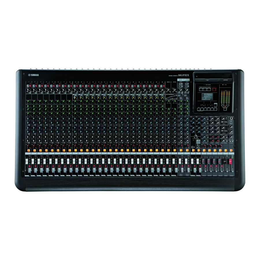
About the models X-pressive EQ The MGP32X and MGP24X feature a different number of mon- aural input channels and COMP control knobs. The MGP32X has The shelving EQ (low/high) on the mono input channels features 24 monaural input channels and the MGP24X has 16. The... -
Page 7: Setup
Failure to do so may result in loud noise NOTE bursts that can damage your equipment, your ears, or both. If the PEAK indicator lights frequently, slowly lower the channel faders a little to avoid distortion. MGP32X/MGP24X Owner’s Manual... -
Page 8: Setup Example
Setup example Computer/Audio interface Microphones for Powered monitor DJ mixer talkback speakers DVD player (voice) CD player Lamp (Yamaha LA-1L) Foyer etc. Stage Microphone Powered CH24 {CH16} (for MC) Power amp Powered monitor speakers subwoofer (For musician monitoring) Powered speakers... - Page 9 Setup Top panel USB device iPod/iPhone Headphones Compressor Rear panel *The illustrations show the panel of the MGP32X. CAUTION • When using a condenser Instrument, Microphone microphone, set the +48V Microphone phantom switch to ON (page 11). Bass * If electric guitars and basses can be con- nected directly to the mixer’s inputs, use a...
-
Page 10: Controls And Connectors
STEREO master section (page 21) MONO master section (page 21) GROUP section (page 20) FX RTN (effect return) section (page 17) Rear panel Channel I/O connectors section (page 22) Master I/O connectors section (page 22) Power section (page 23) MGP32X/MGP24X Owner’s Manual... -
Page 11: Channel Control Block
Turn it on ( if you have connected a line-level device. Mono channels Stereo channels w +48V switch and indicator 1–24 (MGP32X) 25–32 (MGP32X) Toggles phantom power on and off. When this switch is 1–16 (MGP24X) 17–24 (MGP24X) -
Page 12: Input Select Switch
Controls and Connectors y DUCKER SOURCE indicator Mono channels Stereo channels The indicator of the selected input source (CH24 {CH16} or 1–24 (MGP32X) 25–32 (MGP32X) GROUP1) comes on. The input source can be selected on the 1–16 (MGP24X) 17–24 (MGP24X) display (page 37). - Page 13 • The ON switch does not affect the operation of the PFL switch (@1 ) . You can monitor the channel’s pre-fader signal through the PHONES jack even when the ON switch is off. • To reduce noise, turn all unused channels off. MGP32X/MGP24X Owner’s Manual...
- Page 14 Controls and Connectors Mono Channel 1–2 3–4 AUX1 AUX2 AUX3 AUX4 Stereo Channel MGP32X/MGP24X Owner’s Manual...
-
Page 15: Master Control Block
Up to 64GB of the capacity for the USB device is guaranteed • The unit’s iPod/iPhone IN connector is dedicated to by Yamaha. (However, Yamaha cannot guarantee operation iPod/iPhone use only. Please do not connect other USB for all the USB devices). The supported file system is FAT32. -
Page 16: Display Section
The PEAK indicator lights red when the level hits the clipping point. NOTE The PFL signal has display priority over the AFL signal when an input channel’s PFL switch is on. MGP32X/MGP24X Owner’s Manual... -
Page 17: Fx Rtn (Effect Return) Section
Rotate this knob from the center “OFF” position to the right to adjust the send level from FX1 to FX2, and to the left to adjust the send level from FX2 to FX1. Only the pre-fader signal can be sent. MGP32X/MGP24X Owner’s Manual... -
Page 18: Send Master Section
(0 dB). r AFL switch and indicator When the AFL switch is on, the indicator will light and the sig- nal after the MATRIX master knob is output to the PHONES and MONITOR OUT jacks for monitoring. MGP32X/MGP24X Owner’s Manual... -
Page 19: Usb In/Ipod In Section
• TO MONITOR ( ): Sends to the MONITOR OUT jacks and PHONES jack. NOTE CH29/30, 31/32 {CH21/22,23/24} can be selected as the desti- nations of the signal input from the connected USB device or iPod/iPhone (pages 34, 36). MGP32X/MGP24X Owner’s Manual... -
Page 20: Talkback Section
AFL switch are on. To monitor the post-fader signal, make sure to turn off all PFL switches. • If the PFL (preferred) is enabled, the AFL indicator does not light, even if the AFL switch is pressed. MGP32X/MGP24X Owner’s Manual... -
Page 21: Mono Master Section
REO bus to the MONO OUT jack. fader signal, make sure to turn off all PFL switches. t STEREO master fader Adjusts the level of the signal output from the STEREO bus to the STEREO OUT jack. MGP32X/MGP24X Owner’s Manual... -
Page 22: Rear Input/Output Block
* Impedance balanced Connection to an INSERT jack requires a special insertion Since the hot and cold terminals of impedance balanced cable as illustrated below. Use a separately-sold Yamaha inser- output jacks have the same impedance, these output jacks tion cable (YIC025/050/070). -
Page 23: Power Section
This is an XLR-4-31 connector that supplies power to a sepa- to unplug the power cord from the wall AC outlet. rately sold gooseneck lamp (the Yamaha LA1L is recom- mended). NOTE... -
Page 24: Basic Operations And Display
• ERROR This screen appears when a problem is detected in the w GEQ status MGP32X/MGP24X internal connection. Displays the status of the GEQ when on (highlighted) or off (normal display), and the graphics. Pressing the HOME but- Press Knob 2 to close the screen. In the case of MESSAGE, the ton switches the L and R displays. -
Page 25: Operations Of The Screen
(first page) of each screen to call up the list. Rotate Knob 1 to select the desired program/title, and then press Knob 1 to actually select it. Exiting the screen To return to the HOME screen from the current screen, press the HOME button. MGP32X/MGP24X Owner’s Manual... -
Page 26: Using Effects (Fx)
Using Effects (FX) Rotate Knob 2 to adjust the effect depth. The MGP32X/MGP24X features two built-in effects; FX1 and FX2. FX1 has REV-X reverb (8 types), while The value on the lower right side of the screen will change on FX2 has SPX multi effects (a total of 16 types, including the display. -
Page 27: Applying Two Effects Simultaneously
Turn on the ON switch of the FX1 RTN channel, and then raise the FX1 RTN fader to adjust the Exiting the screen effect depth. Press the HOME, GEQ, COMP, USB, or SETUP button in the display section to switch to the corresponding screen. MGP32X/MGP24X Owner’s Manual... -
Page 28: Using Graphic Eq
The confirmation message “Reset GEQ Gains?” appears. Press Knob 2 to select “OK,” or Knob 1 to can- cel. Press Knob 2 to select “OK,” or Knob 1 to can- All frequency gains will be reset. cel. The GEQ type will be changed. MGP32X/MGP24X Owner’s Manual... -
Page 29: Finding And Removing Feedback
When the final adjustment has been made, press Knob 2. Offset will be added only to the setting value of the adjusted frequency. Repeat steps 2 -5 as necessary to adjust the GEQ settings. MGP32X/MGP24X Owner’s Manual... -
Page 30: Calling Up/Saving The Geq Program
Rotate or press Knob 1 to call up the program Eight user programs are available that you can freely edit and list. save on the MGP32X/MGP24X. Calling up the program Press the GEQ button below the display repeatedly if necessary until the PROGRAM page appears. -
Page 31: Using The Compressor
Specifying the threshold About the master compressor Press the COMP button below the display The MGP32X/MGP24X features two master compressors: Comp repeatedly if necessary until the (2/4) THRESH- and Multiband. The Comp type has a simple single band, while OLD page appears. -
Page 32: Calling Up/Saving The Compressor Program
The current setting will be overwritten as a user program. NOTE • You can also cancel saving by pressing the COMP button. • Use the MGP Editor ( page 6) to change the name of the user program as desired. MGP32X/MGP24X Owner’s Manual... -
Page 33: Recording/Playing Back
USB device from the USB IN connector or power-off the MGP32X/MGP24X. Doing so may damage your USB Rotate Knob 1 to select “Rec Form,” and then device, or damage the data in the MGP32X/MGP24X and/ rotate Knob 2 to select one of the following or in the USB device. -
Page 34: Playing Back Songs From A Usb Device
Knob 1 to confirm it. page appears. Playback starts. Title Playback mode Artist information One song All songs Repeat one song Repeat Progress bar all songs Elapsed recording/play- Remaining recording/play- back time back time (hours, minutes, seconds) (hours, minutes, seconds) MGP32X/MGP24X Owner’s Manual... - Page 35 To the upper folder Song Folder NOTE The title list supports half-size alphabet and numbers only. Other characters are converted into “ .” Rotate Knob 1 to select a song (e), and then press Knob 1. Playback starts. MGP32X/MGP24X Owner’s Manual...
-
Page 36: Playing Back Songs From An Ipod/Iphone
In this case, change the recording format to a for- knob) and the level control for channels 31/32 {23/24} at the mat with a high compression rate, such as MP3:128k, MP3:192k, same time. Raising both may cause unnatural flanging in the or MP3:256k. sound. MGP32X/MGP24X Owner’s Manual... -
Page 37: Using Other Functions
Knob 2 to set it to “ON.” For the MGP32X unit connect the microphone to CH24 and The LPF indicator next to the MONO master fader comes on for the MGP24X unit connect the microphone to CH16, or assign the source channel to GROUP OUT 1. -
Page 38: Using The Leveler Function
“#1” in the parameter name indicates CH29/30 {CH21/22}, NOTE and “#2” indicates CH31/32 {CH23/24}. For details about the parameters, refer to the Appendix (page 45). NOTE For details about the parameters, refer to the Appendix (page 45). MGP32X/MGP24X Owner’s Manual... -
Page 39: Initializing The Unit To The Factory Default Settings (Resetting User Memory)
Initializing the unit to the factory default settings (resetting user mem- ory) The MGP32X/MGP24X unit has a function to reset user memory by initializing the unit to the factory default settings. The parame- ter settings and user programs will be reset to the factory default settings. -
Page 40: Troubleshooting
WAV or MP3:320k, a high transmission speed is required. Change the recording to a format with a high compression rate: MP3:128k, MP3:192k, or MP3:256k. If the memory is fragmented significantly, try running a defragmentation program on the com- puter. MGP32X/MGP24X Owner’s Manual... - Page 41 Is the GAIN knob on the stereo channels adjusted appropriately? The Leveler is not enabled. The leveler may not be enabled if you increase the gain too much. * If any specific problem should persist, please contact your Yamaha dealer. MGP32X/MGP24X Owner’s Manual...
-
Page 42: Appendix
USB device was slow. Storage Full! The USB device capacity is insufficient. ERROR This error screen appears when trouble is found in a connection inside the MGP32X/MGP24X. Please contact your Yamaha dealer. Message Meaning Device Check Error! There is a problem in the device indicated by xxxxxxxx, or in the connection between the XXXXXXXX device and the CPU. -
Page 43: Effect Program List
Creates a thick sound by multiplexing the sound. DOUBLER Creates an illusion of two people singing the same phrase. Reproduces a lo-fi feel in the style of the AM radio. Adjust the parameter to change the frequency range to be RADIO VOICE emphasized. MGP32X/MGP24X Owner’s Manual... -
Page 44: Parameter List
Number of phase shift stages FX2 SPX (13: FLANGER) Parameter Range Description Frequency 0.00 – 39.7 Hz Modulation frequency Depth 0 – 127 Modulation depth FB Level -63 to +63 Feedback level Delay 0.0 – 50.0 ms Delay offset MGP32X/MGP24X Owner’s Manual... - Page 45 If a signal higher than a specified threshold level is input, the output level is adjusted to the specified level. Parameter Range Description Threshold -60 to 0 dB This determines the level of input signal required to trigger the leveler. Out Gain -20 to +40 dB This sets leveler’s output signal level. MGP32X/MGP24X Owner’s Manual...
-
Page 46: Jack List
Tip: L PHONES Ring: R Sleeve: Ground Tip: Hot LINE (stereo channels) Sleeve: Ground Sleeve Phone plug * These jacks will also accept connection to phone plugs. If you use monaural plugs, the connection will be unbalanced. MGP32X/MGP24X Owner’s Manual... -
Page 47: Dimensions
Appendix Dimensions MGP32X 1027 MGP24X Unit: mm MGP32X/MGP24X Owner’s Manual... -
Page 48: Specifications
*3 Maximum voltage gain is measured under the condition that all faders and GAIN knobs are at maximum. PAN/BAL knob is panned hard left or right. European Models Inrush Current based on EN 55103-1:2009 4.5A (on initial switch-on) 3.5A (after a supply interruption of 5s) Conforms to Environments: E1, E2, E3 and E4 MGP32X/MGP24X Owner’s Manual... -
Page 49: Phones Out
MONO CH Input Mics Phone Jack -16 dB -36 dBu (12.3 mV) -16 dBu (123 mV) +4 dBu (1.23 V) MGP32X: 1–24 3 kΩ -34 dB -54 dBu (1.55 mV) -34 dBu (15.5 mV) -14 dBu (155 mV) 600 Ω... -
Page 50: General Specifications
Input Channel EQ HIGH 8 kHz, shelving MID MGP32X: CHs 1–24, 29–32: 250 Hz to 5 kHz, peaking CHs 25–28: 2.5 kHz, peaking MGP24X: CHs 1–16, 21–24: 250 Hz to 5 kHz, peaking CHs 17–20: 2.5 kHz, peaking LOW 125 Hz, shelving Input Channel Compressor Parameters (ratio, threshold, output gain) are controlled by one knob. -
Page 51: Index
Capacity ............33 File format ............. 33 Initializing ............39 Format ............33 Instruments ............7 Playing back ..........33 iPod/iPhone ..........15, 36 Recording ............33 USB device recorder ......... 15 Jack List .............46 Volume balance ..........13 Appendix MGP32X/MGP24X Owner’s Manual... -
Page 52: Block Diagram And Level Diagram
Appendix Block Diagram and Level Diagram MGP32X/MGP24X Owner’s Manual... - Page 53 Appendix MGP32X/MGP24X Owner’s Manual...
- Page 54 MGP32X/MGP24X Owner’s Manual...
- Page 55 Compliance with FCC regulations does not guarantee that interference will not occur in all * This applies only to products distributed by YAMAHA CORPORATION OF AMERICA. 이 기기는 가정용(B급) 전자파적합기기로서 주로 IMPORTANT NOTICE FOR THE UNITED KINGDOM 가정에서...
- Page 56 Niederlassung und bei Yamaha Vertragshändlern in den jeweiligen Bestimmungsländern erhältlich. Pour plus de détails sur les produits, veuillez-vous adresser à Yamaha ou au distributeur le plus proche de vous figurant dans la liste suivante. Para detalles sobre productos, contacte su tienda Yamaha más cercana o el distribuidor autorizado que se lista debajo.