NEC POWERMATE eco Service And Reference Manual
Microdesktop computer
Hide thumbs
Also See for POWERMATE eco:
- Release notes (1 page) ,
- Getting started manual (28 pages) ,
- Illustrated parts breakdown (4 pages)

Related Manuals for NEC POWERMATE eco


Summary of Contents for NEC POWERMATE eco
- Page 1 PowerMate eco™ Microdesktop Computers e c o O W E R A T E S E R V I C E A N D R E F E R E N C E M A N U A L...
- Page 2 NERGY for energy efficiency. PowerMate eco is a trademark of NEC Solutions (America), Inc.; NEC is a registered trademark of NEC Corporation and/or one of its subsidiaries. All are used under license. E is a U.S. registered trademark of the U.S.
-
Page 3: Table Of Contents
Contents Preface........................... vii Abbreviations ......................... ix 1 System Overview Product Description....................... 1-2 External Features ......................1-4 Internal Components ..................... 1-7 LCD Unit....................... 1-8 Base Unit ....................... 1-9 Software ........................1-10 Preloaded Software ....................1-10 PowerMate eco Application and Driver CD ............1-10 PowerMate eco Product Recovery CD .............. - Page 4 Speaker Assembly Removal ..................3-20 Base Cover Assembly Removal................... 3-21 Interface Board Assembly Removal ................3-23 Optical Drive Bracket Assembly ................. 3-24 4 Board Layouts System Board ....................... 4-2 Operation Board ......................4-4 Legacy Board ....................... 4-4 Interface Board ......................4-5 5 Illustrated Parts Breakdown Replaceable Parts List....................
- Page 5 List of Figures PowerMate eco Main System Components ..............1-2 PowerMate eco System — Front Features..............1-4 System Controls and LEDs.................... 1-4 Typical Optical Drive Features ..................1-5 PowerMate eco System — Rear Features............... 1-5 I/O Connectors......................1-6 Right Side Features ....................... 1-6 Left Side Features ......................
- Page 6 PowerMate eco Series Disassembly Sequence ............... 3-2 PowerMate eco Replacement Parts List ................. 5-2 PowerMate eco IPB ...................... 5-4 Problems and Solutions....................7-5 NEC Solutions (America), Inc. Support Services ............8-2 PowerMate eco Specifications..................9-2 System Specifications ....................9-2 Keyboard Specifications ....................9-5 Mouse Specifications ....................
-
Page 7: Preface
The manual includes system setup and configuration information, disassembly procedures, an illustrated parts list, maintenance information, and troubleshooting procedures. The manual is prepared for NEC Solutions (America), Inc.-trained customer engineers, service center staff, and depot repair personnel. The content of this manual is organized as follows. -
Page 8: Abbreviations
Abbreviations ampere direct memory access alternating current DMAC DMA controller acknowledge Desktop Management Interface accelerated graphics port disk operating system ASIC application-specific integrated circuit DRAM dynamic RAM advanced technology (IBM PC) digital versatile disc AT attachment DVMT Dynamic Video Memory Technology ATAPI AT attachment packet interface error checking and correction... - Page 9 integrated peripheral controller personal computer inches per second printed circuit board infrared Peripheral Component Interconnect IrDA Infrared Data Association PCMCIA Personal Computer Memory Card International Association Interrupt Request register personal digital assistant Industry Standard Architecture plastic flat package internet service provider parallel input/output interrupt request pixel...
- Page 10 SVGA Super Video Graphics Array switch T&D test and diagnostics thin film transfer Technical Support Center transistor/transistor logic tracks per inch UART universal asynchronous receiver/transmitter ultra high frequency Underwriter’s Laboratories unified memory architecture uninterruptible power supply uniform resource locator universal serial bus volt volts, alternating current video cassette recorder...
-
Page 11: System Overview
System Overview Product Description External Features Internal Components Software Security... -
Page 12: Product Description
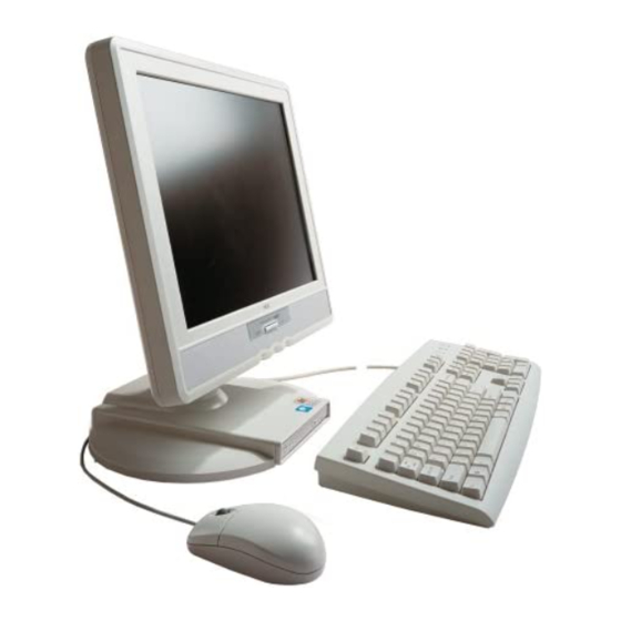
This chapter provides an overview of the NEC PowerMate eco™ system and includes descriptions of: system hardware front, rear, and side features internal components software features security features. Product Description The NEC PowerMate eco is a microdesktop computer featuring a space-saving “boxless”... -
Page 13: Powermate Eco System Configuration Summary
Chapter 9 for a detailed list of PowerMate eco specifications. PowerMate eco System Configuration Summary Component Description System Board NEC proprietary board Processor Transmeta Crusoe TM5800, 133-MHz or higher Front Side Bus (FSB) Cache 64-KB x 2 L1 cache and 512-KB L2 cache Chip Set North Bridge —... -
Page 14: External Features
External Features See the following figures to identify PowerMate eco features on the front, rear, and sides of the system. PowerMate eco System — Front Features A – LCD Panel D – Optical Drive B – Left Speaker E – Right Speaker C –... -
Page 15: Typical Optical Drive Features
G – Rear Cover Lock C – LAN Port H – I/O Connector Cover D – USB Ports (2) I – Vents E – USB Cable Lock Do not block vents while the NEC PowerMate eco system is in use. System Overview 1-5... -
Page 16: I/O Connectors
I/O Connectors A – Serial Port C – PS/2 Mouse Port ® B – PS/2 Keyboard Port D – Parallel Printer Port Right Side Features A – Line Out Jack C – Microphone Jack B – Line In Jack 1-6 System Overview... -
Page 17: Internal Components
Left Side Features A – PC Card Eject Buttons (2) C – USB Ports (2) B – PC Card Slots (2) Internal Components The PowerMate eco system has two main parts, the LCD unit and the base unit. See the following sections for a description of components in these main parts. -
Page 18: Lcd Unit
LCD Unit The LCD unit contains most of the system components (see the following figures): LCD panel components — located at the front of the LCD unit; includes the LCD front panel, LCD panel, and power inverter board. Operation board — located below the LCD panel at the front of the LCD unit; includes the power button, brightness buttons, volume control, power LED, optical/hard drive LED, and connectors for the speaker cables and cable to the system board. -
Page 19: Base Unit
LCD Unit Components — Rear A – System Board (under system board shield) D – Hard Drive Assembly B – Legacy Board (behind system board shield) E – Hinge Assembly C – System Board Shield Base Unit The base unit contains the following components: Optical drive assembly —... -
Page 20: Software
Software NEC Solutions (America), Inc. provides a variety of applications and hardware utilities with the system to take advantage of the system hardware capabilities. Preloaded Software ® ® The system comes preloaded with the Microsoft Windows 2000 Professional/Windows XP Professional operating system. -
Page 21: Windows Network Security Features
Windows Network Security Features The Windows Network Security feature is available through the Microsoft Windows operating system. See the Windows documentation for details. Security Lock Slot The security lock slot at the rear of the system accepts a Kensington Security Standard connector or other locking device to physically protect the system unit from intrusion. -
Page 22: Setup And Configuration
Setup and Configuration System Setup Jumper Settings BIOS Setup Utility FLASH Utility PowerMate eco Application and Driver CD PowerMate eco Product Recovery CD... -
Page 23: System Setup
Do not cover or place objects on the AC adapter. Keeping the adapter clear of objects lets the adapter cool properly during use. Only use the AC adapter that comes with your NEC PowerMate eco system. Although other adapters look similar, using them can damage your system. -
Page 24: Jumper Settings
Microsoft Windows XP Professional, or Microsoft Windows 2000 Professional. Once you choose the operating system, you cannot change it. The NEC PowerMate eco Product Recovery CD that ships with your system only restores the operating system you choose during the initial Microsoft Windows setup. - Page 25 Jumpers are set correctly at the factory for your configuration. Only change the appropriate jumper setting for your requirement. Otherwise, keep the jumpers at their factory settings. Set jumpers as follows. Close all applications, shut down the operating system, turn off system power, and unplug the AC power adapter and power cord from the power source and the back of the system.
-
Page 26: System Board Jumper Settings
System Board Jumper Settings Function Jumper Settings Description Password Factory setting. Sets normal operation. Clear Clears the system password. To clear the password, turn off system power, remove the jumper from the J4 pins, and power on the system. Power off the system, replace the jumper on the J4 pins, and power on the system. -
Page 27: Bios Setup Utility
However, you should run the BIOS Setup utility to set features that customize the system, such as security features. NEC Solutions (America), Inc. recommends that the current BIOS Setup parameters be printed out or written down and the information stored in a safe place. This lets you restore the system to the current parameters if you need to clear CMOS or you are replacing the CMOS battery (see the previous section, “Jumper Settings”... -
Page 28: Main Menu
Use the keys shown on the bottom of the Main menu to make selections or exit the current menu. The following table describes the navigation keys. Setup Key Functions Function Provides help for the parameter field being displayed. Exits the menu. Up or down arrow keys Moves the cursor up and down for item selection. -
Page 29: Main Menu Items
Main Menu Items Menu Item Settings (default is bold) System Time Set system time in this field. Press Tab or Enter to move between hour, minute, and second fields. Example: 09:30:50 System Date Set system date in this field. Press Tab or Enter to move between month, date, and year fields. - Page 30 Main Menu Items Menu Item Settings (default is bold) Type User, Auto, None, CD-ROM, ATAPI Removable, IDE Removable When set to Auto, the values for Cylinders, Heads, Sectors, and Maximum Capacity are displayed but are read only. When set to Auto, the BIOS detects what the drive is capable of, not the translation mechanism that was used to format the drive.
- Page 31 Main Menu Items Menu Item Settings (default is bold) Transfer Mode Standard, Fast PIO1, Fast PIO2, Fast PIO3, Fast PIO4, Fast PIO3/DMA1, Fast PIO4/DMA2 Selects the method for moving data to and from the drive. When Type is set to Auto, the value in the field is auto- detected and the field is read only.
-
Page 32: Advanced Menu
Main Menu Items Menu Item Settings (default is bold) BIOS Revision Displays the BIOS revision number. This field is read-only and cannot be changed from the BIOS Setup. Example: 183A0100 Advanced Menu Choose the Advanced menu by selecting Advanced in the legend bar on the Main menu screen. Other Advanced menu options are available by selecting submenus. - Page 33 Advanced Menu Menu Item Settings (default is bold) Base I/O 3F8, 2F8, 3E8, 2E8 Address Selects the base I/O address for serial port A. Interrupt IRQ3, IRQ4 Selects the IRQ for serial port A. Parallel Port Disabled, Enabled, Auto Setting at Enabled allows the user to configure the port. Setting at Auto enables the BIOS or operating system to configure the port.
-
Page 34: Security Menu
Advanced Menu Menu Item Settings (default is bold) Event Logging Enabled, Disabled Selecting Enabled permits logging of DMI events. Mark DMI Events As Press Enter. Select Yes or No to “Mark all Events as read?” Read Network Boot Agent Enabled, Disabled Select “Enabled”... -
Page 35: Power Menu
Security Menu Items Menu Item Settings (default is bold) Security Mode Press Enter to access the Security Mode. Use this mode to select Password (default), SmartCard, or FingerPrint. Press Enter to open the selected field. Use the SmartCard field to assign access to the SmartCard Reader by the supervisor and/or user. -
Page 36: Boot Menu
Power Menu Settings Menu Item Settings (default is bold) System Switch Sleep Button, Power Button Select Power Button to turn the system on or off. Resume On Off, On Modem Ring Setting to On allows the system to wake up when an incoming call is detected on the modem (if installed). -
Page 37: Exit Menu
(America), Inc. for assistance (see Chapter 8, Services and Support). Update the FLASH ROM with a BIOS Flash diskette. You can get the diskette from NEC Solutions (America), Inc. or download the BIOS from the NEC Solutions (America), Inc. Web site. -
Page 38: Powermate Eco Application And Driver Cd
Choose the restore option carefully to prevent losing data and applications installed on the system. NEC Solutions (America), Inc. suggests that you contact Technical Support Services for assistance in restoring the hard drive. See Chapter 8 for information on obtaining NEC Solutions (America), Inc. support. - Page 39 Use the Product Recovery CD to perform a Full Disk Drive restore as follows. Disconnect all peripherals and power on the system. Before using the Product Recovery CD, enter the BIOS Setup utility, record the current settings, and restore the BIOS default settings. Save the default settings before exiting the BIOS Setup utility.
-
Page 40: Performing Partition Only Restore
Only use the Partition Only restore option if the preinstalled software on drive C: is unusable. If you have any question about performing a Partition Only restore, NEC Solutions (America), Inc. suggests that you contact Technical Support Services before starting the restore procedure. See Chapter 8 for information about obtaining support from NEC Solutions (America), Inc. - Page 41 At the prompt, remove the CD from the drive. Press , click , or press Enter Reboot Alt-R reboot your system. A series of hardware detection screens display, the system reboots, and the Windows Setup screen appears. Follow the screen prompts to set up Windows. 2-20 Setup and Configuration...
-
Page 42: Disassembly And Reassembly
Disassembly and Reassembly Optical Drive Rear Cover Memory Module Hard Drive System Board Shield Legacy Board System Board CMOS Battery PC Card Bay Front LCD Cover Power Button Assembly LCD Panel Power Inverter Board Operation Board Brightness Button Assembly Speaker Assemblies Base Cover Assembly Interface Board Optical Drive Bracket... -
Page 43: Powermate Eco Series Disassembly Sequence
This chapter contains step-by-step disassembly procedures for the PowerMate eco system. A disassembly figure is provided with most procedures. Chapter 5 includes a parts list and an illustrated parts breakdown diagram showing an exploded view of the system. A small flat-head screwdriver, a small Phillips-head screwdriver, and an antistatic wrist strap are the only required tools. -
Page 44: Optical Drive Removal
When disassembling the system, follow these general rules. Turn off the system and disconnect the AC power adapter and AC power cord from the power source and the system. Disconnect all peripherals before disassembling the system. Do not disassemble parts other than those specified in the procedure. All screws are Phillips-head, unless otherwise specified. -
Page 45: Rear Cover Removal
Return the optical drive release button to its recessed position on the system base. Note To replace the optical drive, be sure to press the drive firmly into the drive bay to secure it into the drive bay connector. Rear Cover Removal Remove the rear cover as follows. -
Page 46: Locating The Cover Slots And Cover Lock Bracket
Replace the rear cover as follows. Press the cover lock bracket in for the cover replacement. Insert the top cover tabs into the top cover slots on the LCD unit (see the following figure). Press the side and bottom cover tabs into the side and bottom slots on the LCD unit. Locating the Cover Slots and Cover Lock Bracket A –... -
Page 47: Memory Module Removal
Memory Module Removal Remove the SO-DIMM memory module as follows. Close all applications, shut down the operating system, turn off system power, and unplug the AC power adapter and power cord from the power source and the back of the system. Turn off and disconnect all peripherals. -
Page 48: Removing The Memory Module
Remove the memory module as follows. Press the locking tabs away from the sides of the module until the module pops up at an angle. Pull the memory module out of the slot along the angle and store it in a static-free bag. Removing the Memory Module A –... -
Page 49: Hard Drive Removal
Inserting the tabbed end first, replace the memory slot cover. Secure it with the retaining screw. Replacing the Memory Slot Cover A – Tabbed End of Memory Slot Cover B – Screw Replace the rear cover (see “Rear Cover Removal” earlier in this section). Position the system on its base. -
Page 50: System Board Shield Removal
Removing the Hard Drive A – Cable loop B – Hard Drive Bracket Pull Tab System Board Shield Removal Remove the system board shield as follows. Close all applications, shut down the operating system, turn off system power, and unplug the AC power adapter and power cord from the power source and the back of the system. -
Page 51: Legacy Board Removal
Remove the three screws securing the system board shield to the LCD unit (see the following figure). Removing the System Board Shield B – System Board Shield A – Screws (3) Disconnect the shield’s legacy board interface cable from the system board. Legacy Board Removal Remove the legacy board as follows. -
Page 52: System Board Removal
Remove two screws securing the legacy board to the inside of the system board shield (see the following figure). Remove the board from the system board shield. Disconnect the interface cable from the legacy board. Removing the Legacy Board A – Screws (2) C –... -
Page 53: Removing The System Board Shield And Side Panels
Remove the three screws securing the system board shield to the system board and remove the shield (see following figure). Disconnect the shield’s legacy board interface cable from the system board. Remove the left and right side panels by pressing the top and bottom release tabs. Removing the System Board Shield and Side Panels A –... -
Page 54: Cmos Battery Removal
Removing the System Board A – System Board Screws (3) B – Heatsink B – Heatsink Screws (4) C – Retaining Tabs CMOS Battery Removal Remove the 3-volt lithium battery from the system board as follows. If possible, enter the BIOS Setup utility and record the settings (see Chapter 2, “Setup and Configuration”). -
Page 55: Removing The Cmos Battery
Insert a small flat-head screwdriver at the pry point ( in the following figure) and carefully pry up on the battery until it pops out of the socket. Removing the CMOS Battery A – Pry Point B – Battery The battery can explode if it is incorrectly replaced or improperly discarded. -
Page 56: Pc Card Bay Removal
PC Card Bay Removal Remove the PC Card bay as follows. Remove the system board (see “System Board Removal” earlier in this chapter). Position the system board with the processor side of the board facing down. Remove the four screws securing the PC Card bay to the system board (see the following figure). -
Page 57: Front Lcd Cover Removal
Front LCD Cover Removal Remove the front LCD cover to access the following components: power button assembly logo plate assembly speaker assembly operation board assembly brightness button assembly LCD panel. Remove the front LCD cover as follows. Close all applications, shut down the operating system, turn off system power, and unplug the AC power adapter and power cord from the power source and the back of the system. -
Page 58: Power Button Assembly Removal
Power Button Assembly Removal Remove the power button assembly as follows. Remove the front LCD cover (see the previous section “Front LCD Cover Removal”). Locate the power button assembly on the inside of the front LCD cover (see the following figure). -
Page 59: Power Inverter Board Removal
Carefully lift the LCD panel out of the LCD unit. Holding the LCD panel, disconnect cables as follows: Disconnect the LCD video cable from the rear of the LCD panel (not shown). Unplug four power inverter cable connectors from the inverter board (see the following figure). -
Page 60: Operation Board Removal
Removing the Inverter Board A – Inverter Board C –Power Cable B – Screws (2) Operation Board Removal Remove the operation board from the LCD unit as follows. Remove the front LCD cover (see “Front LCD Cover Removal” earlier in this chapter). Disconnect the operation board interface cable and the speaker assembly cables from their connectors on the operation board (see the following figure). -
Page 61: Brightness Button Assembly Removal
Brightness Button Assembly Removal Remove the brightness button assembly from the LCD unit as follows. Remove the front LCD cover (see “Front LCD Cover Removal” earlier in this chapter). Remove the screw securing the brightness button assembly to the LCD unit. Removing the Brightness Button Assembly A –... -
Page 62: Base Cover Assembly Removal
Removing the Left Speaker Assembly A – Screws (2) B – Left Speaker Cables Base Cover Assembly Removal Remove the base cover assembly from the base unit as follows. Close all applications, shut down the operating system, turn off system power, and unplug the AC power adapter and power cord from the power source and the back of the system. -
Page 63: Removing The Rear Hinge Cover
Remove the rear hinge cover by pivoting the cover up at points as shown in the following figure. Removing the Rear Hinge Cover A – Rear Hinge Cover C – Pivot Point C B – Pivot Point B Carefully position the system on a clean, flat, soft surface, with the LCD panel facing down. To prevent damage to your LCD panel screen, be sure your work surface is clean, flat, smooth and free of any objects before positioning the system face down. -
Page 64: Interface Board Assembly Removal
Remove the 10 screws securing the bottom base plate to the base cover. Removing the Bottom Base Plate B – Screw (1 of 10) A – Bottom Base Plate Pivot the bottom base plate around to access the cables. Disconnect and label cables. Undo the cable clamp. A small flat-head screw drive is handy to release some of the cable connectors. -
Page 65: Optical Drive Bracket Assembly
Remove the interface board assembly as follows. Remove four screws that secure the board to the bottom base plate. Lift the assembly off the base plate. Remove two screws securing the interface board to the assembly. Carefully slide the board out from the connector panel Removing the Interface Board Assembly A –... -
Page 66: Board Layouts
Board Layouts System Board Operation Board Legacy Board Interface Board... -
Page 67: System Board
This chapter provides board layouts for the boards in the PowerMate eco system. Information includes jumper, connector, and socket identification and location for the following boards: System board (G1AMS) Operation board (G1AMV) Legacy board (G1AMU) Interface board (G1AMT). Note For the location of connectors on the outside of the PowerMate eco system, see “External Features”... -
Page 68: System Board Jumper Location — Side 1
Jumpers are located on the side of the system board facing the rear cover. See the following figure to locate the jumpers on the system board. See “Jumper Settings” in Chapter 2 for a description of the jumper settings. System Board Jumper Location — Side 1 A –... -
Page 69: Operation Board
Operation Board The operation board (G1AMV) is located below the LCD panel on the front of the LCD unit (see “Operation Board Removal” in Chapter 3). The identification and location of connectors, LEDs, and controls on the operation board are shown in the following figure. -
Page 70: Interface Board
Interface Board The interface board (G1AMT) is located at the rear of the base unit (see “Interface Board Removal” in Chapter 3). The identification and location of connectors on the legacy board are shown in the following figure. Interface Board Connectors A –... -
Page 71: Illustrated Parts Breakdown
Illustrated Parts Breakdown Replaceable Parts List Illustrated Parts Breakdown... -
Page 72: Replaceable Parts List
PowerMate eco microdesktop computer. The IPB diagram is at the end of this chapter. Note Repairs for the PowerMate eco system are done at the depot only. A Depot Repair Form is available at the Service and Support area of the NEC Solutions (America), Inc. Web site (www.necsolutions-am.com\mobilesolutions). Replaceable Parts List The following table lists the replaceable parts for the PowerMate eco microdesktop computer. - Page 73 PowerMate eco Replacement Parts List Item No. on IPB Parts Description EIDE Hard Drive Assembly Hard Drive Ribbon Cable Memory Upgrade Slot Cover Legacy Board (G1AMU) NOTE: The following parts are not shown on the IPB. ---- AC Power Adapter (AU80001) ---- AC Power Cord ----...
-
Page 74: Illustrated Parts Breakdown
Illustrated Parts Breakdown The following figure shows the IPB for the PowerMate eco system. Each replaceable part on the IPB is identified with a number that cross-references to the replaceable parts list. PowerMate eco IPB 5-4 Illustrated Parts Breakdown... -
Page 75: Preventive Maintenance
Preventive Maintenance System Cleaning Keyboard Cleaning Mouse Cleaning... -
Page 76: System Cleaning
This chapter contains general information for cleaning and checking the PowerMate eco microdesktop computer. The LCD/base units, keyboard, and mouse require cleaning and checking at least once a year, more often if they are used in a dusty environment. No other scheduled maintenance is required. Unplug all power cords before performing any maintenance. -
Page 77: Mouse Cleaning
Do not wet or dampen the keyboard’s printed circuit board. If the board accidentally gets wet, thoroughly dry it before reassembling and reattaching the keyboard to the system unit. Mouse Cleaning The mouse has a self-cleaning mechanism that prevents a buildup of dust or lint around the mouse ball and tracking mechanism under normal conditions. -
Page 78: Troubleshooting
Troubleshooting Checklist Diagnostics... -
Page 79: Checklist
System emits continuous beeps. Turn the system off, wait at least five seconds, and turn the system on. If the beeps continue, call the NEC Solutions (America), Inc. Technical Support Center (see Chapter 8, “Services and Support”). System does not maintain date, time, system configuration information. -
Page 80: External Diskette Drive Problems
System performance appears sluggish. There might be too many applications open. Close any applications that are not being used. Check the Internet browser and Windows for excessive Internet cache files. Delete the cache files as necessary (see the browser and Windows online documentation for details). Check the memory requirements of the software applications. -
Page 81: Keyboard/Mouse Problems
The screen display is fuzzy or flickering; graphics characters or garbage appears on the screen. Check that all connections have been made. Check that the video refresh rate and video driver are correct. Check display properties. Click the right mouse button anywhere on the Windows desktop and a menu appears. -
Page 82: Speaker Problems
Speaker Problems Check the following problems to see the possible cause and solution. No sound from the speakers. Check that the system power is on. Check that the system AC power adapter and AC power cord are connected to the power source and the back of the system unit. - Page 83 Problems and Solutions Problem Symptom Solution 2. Replace the CMOS battery if the date and time must be set each time the system is powered on (see Chapter 3). System halts during loading 1. Power the system off. Check for proper sequence.
- Page 84 Problems and Solutions Problem Symptom Solution Keyboard or mouse LCD panel display has prompt, 1. Check that keyboard/mouse is plugged malfunction but cannot input data using into correct port. keyboard or mouse. 2. If using USB mouse, try different USB port.
- Page 85 Problems and Solutions Problem Symptom Solution CD-ROM drive No sound from disc. 1. Check that system power is on and malfunction (cont’d) volume control on system side adjusted. 2. Check audio software settings. 3. Check disc for dirt, scratches, label side 4.
-
Page 86: Service And Support
Service and Support Contact Information Web Site Services E-mail to Support Services Technical Support Services... -
Page 87: Contact Information
If you have access to the Internet (via a network or modem connection), you can access the Mobile Solutions Division at the NEC Solutions (America), Inc. Web site. You can do this through a commercial online service or through your Internet account. The NEC Solutions (America), Inc. -
Page 88: E-Mail To Support Service
Center. NEC Solutions (America), Inc. support is for U.S. and Canadian customers only; international customers should check with their sales provider. Direct assistance is available 24 hours a day, 7 days a week. Call the NEC Solutions (America), Inc. Technical Support Center, toll free, at (U.S. -
Page 89: Specifications
Specifications Microdesktop System Keyboard Mouse AC Power Adapter Environmental and Safety Compliance... -
Page 90: Microdesktop System
Specifications for the PowerMate eco microdesktop system are listed in the following table. System Specifications Feature Specification Chassis Type — boxless, microdesktop; conforms to NEC Very-Small Form Factor and Flat Panel Display Specifications Dimensions Width: 14.6 in. (370 mm) Depth: 8.9 in (226 mm) Height: 15.5 in. - Page 91 System Specifications Feature Specification Main Memory Standard — 128 MB DDR SDRAM minimum on system board (100- to 133-MHz FSB) plus SDR SDRAM in SO-DIMM socket Expandable — in one SO-DIMM socket (SDR) with 64-, 128-, 256-, or 512-MB SO-DIMM module (66- to 133-MHz FSB, without ECC) Maximum —...
- Page 92 NEC G1AMV — in LCD unit front panel; includes power switch, LEDs, hardware volume control, and speaker interface Interface Board NEC G1AMT — in base unit; includes VersaBay IV, USB, LAN, and DC in interfaces Legacy Board NEC G1AMU — in LCD unit on system board shield; includes parallel,...
-
Page 93: Keyboard
System Specifications Feature Specification Security Password security and I/O control settings in BIOS Setup utility Anti-theft bracket on rear of base system for keyboard and mouse cables Cover lock bracket at rear of LCD unit Kensington lock slot on rear of base system Keyboard Keyboard specifications are listed in the following table. -
Page 94: Ac Power Adapter
UL 1950 3 edition Canadian C-UL C22.2 No. 950-95 ICES-003 Issue 2, Revision 1 Year 2000 YMARK 2000 NEC Y2KTEST.EXE WHQL DMI 2.3 Self Certification Test Suite PC99 All hardware in system is PC99 compliant Energy Star Energy Star Compliant... -
Page 95: Glossary
Glossary applications programs Software designed to perform specific functions, like solving business or mathematical problems. AC Adapter A device that connects to a DC IN port on a computer and to an AC wall outlet to provide AC power for running the system. base RAM Area of system memory between 0 and 640 kilobytes available to the user for operating system and application programs. - Page 96 CMOS Complementary Metal Oxide Semiconductor. A chip that contains nonvolatile memory in a computer. CMOS is backed up by an internal lithium battery that preserves clock/calendar data and system configuration parameters stored in CMOS. cold boot Process of starting up the computer by turning on the power. If power is already on, the process means to turn off the computer and turn it on again.
- Page 97 hardware The electrical and mechanical parts from which a computer is made. hertz (Hz) A unit of frequency equal to one cycle per second. hot key Combination of two or three keys (such as Ctrl-Alt-D) that you press simultaneously for a particular function.
- Page 98 memory Electronic storage area in a computer that retains information and programs. A computer has two types of memory — read-only memory (ROM) and random access memory (RAM). menu A video display of programs or options. microprocessor A semiconductor central processing unit that is the principal component of a microcomputer.
- Page 99 password A string of characters that the user must enter before the system allows access or system privileges. PCMCIA A credit card sized peripheral interface standard for portable devices. Types of PCMCIA cards currently offered by major vendors include fax/modems, LAN, storage cards, and wireless communications devices.
- Page 100 scanner An optical device that reads printed material and converts it to a computer screen image. serial interface An interface that communicates information one bit at a time. serial printer A printer with a serial interface. software Programs that run on a computer, such as operating systems, word processors, and spreadsheets.
- Page 101 Index Summary screen, 2-13 supervisor password, 2-13 system backup reminder, 2-14 AC power system memory, 2-10 adapter specifications, 9-5 system power button, 2-15 components, 1-2, 1-3 system sleep button, 2-15 Acrobat reader, 1-10 USB 2.0, 2-12 Advanced menu, 2-6, 2-11 user password, 2-13 Anti-theft bracket, 1-11 using, 2-6...
- Page 102 CD-ROM PS/2 keyboard, 1-8, 9-4 device setting, 2-8 PS/2 mouse, 1-8, 9-4 drive, 1-2. See also Optical drive serial, 1-8, 9-4 drive bay, 1-9 specifications, 9-4 type, 2-9 system board, 4-2 CD-RW USB, 1-9, 9-4 drive, 1-2. See also Optical drive Contact information, 8-2 Software CD, 1-10 Controls, 1-4, 4-4, 9-4...
- Page 103 Extended memory, 2-10 specifications, 9-4 External features, 1-2, 1-4 Internal features, 1-3 Features Jumpers audio jacks, 1-6 how to set, 2-4 controls and LEDs, 1-4 location, 2-3, 4-3 front, 1-4 settings, 2-3, 2-5 I/O connectors, 1-6 system board, 2-3, 2-5 internal, 1-3 LCD, 1-2 left side, 1-7...
- Page 104 1-8 system board, 1-8 NEC Solutions (America), Inc. LCD video cable, 3-18 contact information, 8-2 LEDs, 1-4, 4-4, 9-4 e-mail to technical support, 8-3 Legacy board Mobile Solutions Division, 8-2 connectors, 4-4 support services, 8-2 description, 1-8 technical support services, 8-3...
- Page 105 serial, 1-8 USB, 1-9 Samsung panel, 2-5 Power SDR memory, 1-3 AC adapter specifications, 9-5 Security components, 1-3 anti-theft bracket, 1-11 DC In connector, 4-5 cover lock, 1-11 menu, 2-14 diskette access, 2-14 output, 1-3 features, 1-10 Power button keyboard mouse lock, 2-14 removal, 3-17 lock slot, 1-11 system switch setting, 2-15...
-
Page 106: Keyboard Specifications
LCD panel, 9-3 powering off, 7-3 legacy board, 9-4 problem checklist, 7-2 mouse, 9-5 problem diagnostics, 7-5 operation board, 9-4 speakers, 7-5 storage devices, 9-3 system, 7-2 system, 9-2 system board, 9-2 weight, 9-2 Storage devices, 9-3 2.0, 2-12 Summary screen, 2-13 CD-ROM boot, 2-15 Supervisor password, 2-13 devices, 1-2... -
Page 107: Battery Replacement
(see Chapter 3, “Disassembly and Reassembly,” for battery replacement procedures). For additional battery replacement information, call NEC Solutions (America), Inc. Technical Support (see Chapter 8 for contact information). There is a danger of explosion if the battery is incorrectly replaced. -
Page 108: Battery Disposal
Battery Disposal The CMOS battery is made of lithium. Contact your local waste management officials for other information regarding the environmentally sound collection, recycling, and disposal of the batteries. LCD Panel Disposal The LCD lamp in the computer’s LCD panel contains mercury. Do not place a used LCD panel in your regular trash. -
Page 109: Declaration Of Conformity
NEC Solutions (America), Inc. DECLARATION OF CONFORMITY We, the Responsible Party NEC Solutions (America), Inc. 15 Business Park Way Sacramento, CA 95828 declare that the product NEC PowerMate eco is in conformity with part 15 of the FCC Rules. Operation of this... - Page 110 819-200904-001 08/02 NEC Solutions (America), Inc. Mobile Solutions Division www.necsolutions-am.com/mobilesolutions...