Table of Contents
Advertisement
Save This Manual
For Future Reference
MODEL NO.
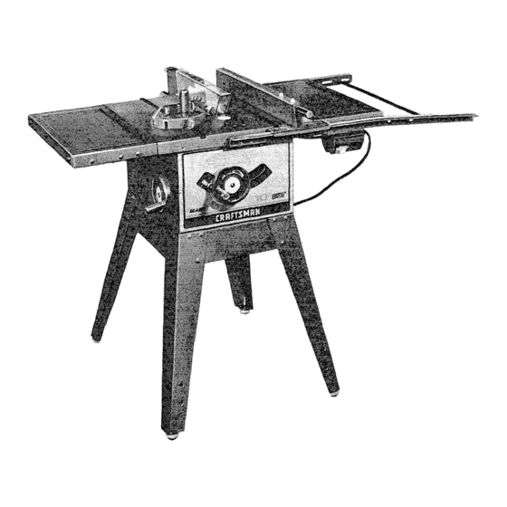
113.226640
SAW WITH
LEGS AND
TWO
TABLE
EXTENSIONS
Serial
Number
Model
and serial
number
may be found
at the rear of the base.
You should
record
both
model
and serial
number
in a safe place
for
future
use.
CAUTION:
READ ALL
INSTRUCTIONS
CAREFULLY
IO-INCH
DIRECT
DRIVE
TABLE SA W
• assembly
• operating
= repair parts
Sold by SEARS,
ROEBUCK
AND
CO.,
Chicago,
IL. 60684
U.S.A-
Part No. 62969
Advertisement
Table of Contents

Related Manuals for Craftsman 113.226640


Summary of Contents for Craftsman 113.226640
- Page 1 Save This Manual For Future Reference MODEL NO. 113.226640 SAW WITH LEGS AND TABLE EXTENSIONS Serial Number Model and serial number may be found at the rear of the base. You should record both IO-INCH model and serial number in a safe place DIRECT DRIVE future...
- Page 2 FULL ONE YEAR WARRANTY' ON CRAFTSMAN TABLE SAW _f w_thm one year from the date of purchase, this Craftsman Table Saw fails due to a defect materia_ or workmanship. Sears will repair it, free of charge. WARRANTY SERVICE IS AVAILABLE...
- Page 3 ADDiTiONAL SAFETY iNSTRUCTiONS FOR TABLE SAWS WARNING: YOUR SAFETY, DO NOT operating immediately until particular OPERATE YOUR SAW UNTIL iT IS COMPLETELY part is proper_y repaired or replaced ASSEMBLED iNSTALLED ACCORDING B Small loose pieces of wood or other obiects INSTRUCTIONS ...
- Page 4 when ripping, use the maximum diameter blade Provide adequate support to the rear for which the saw is designed, since under these sides of the table wider long conditions the spreader is nearest the blade. workpieces. O. Plastic composition (like hardboard) Adjust table inserts...
- Page 5 MOTOR $PECIFmCATION$ ELECTRICAL REQUIREMENTS This saw is designed to use a 3450 RPM motor only. This plug requires a mating 3-COnductor grounded Do not use any motor that runs faster than 3450 type outlet as shown. RPM. It is wired for operation on 110-120 volts, 60 If the outlet you are planning...
- Page 6 CONTENTS WARRANTY ......... Miter Gauge ......GENERAL SAFETY INSTRUCTION B_ade Guard ......FOR POWER TOOLS ....Table Insert ......ADDITIONAL SAFETY INSTRUCTIONS Removing Installing Sawblade ..FOR TABLE SAWS ...... Exacti-Cut ........ MOTOR SPECIF_CATIONS AND ELECTRICAL BASIC SAW OPERATION USING MITER REQUIREMENTS ......
- Page 7 LIST OF LOOSE PARTS Item Part Name Qty. Par_Nam_ Qty. A Miter Gause ......NuL Sa 1/4-29 ....B Ris Fen:e" ......C Bt_'_de G,ua_da_!d Sp_eade_ , ....D HamJwhee! ......B_cket, Co_e,' Su;}po_t .... B_a(iket. CoirIei StlffemI/ , ...."_ E Rip Fe__ce Guide Ba_, _,:'a_ .
- Page 8 2. Insert three truss head screws through the three holes near the top of one leg. Place the side stiffener up to the leg as shown so that the three ASSEMBLE SCREWS screws line up with the holes in the side stiffeners THROUGH HOLES marked with an "X"...
- Page 9 mNSTALLING BEVEL POINTER HANDWHEELS Locate the following parts Bevel Pointer ....... Screw, 8-32 x 3/8 ......Handwheels ........ LOCKWASHER LOCKWASHER Screw, Phillips 10-32 x 3/4 ....Lockwashers, 3/16 I.D. External ..... 1. Fasten bevel pointer to cradae assembly with 8-32 x 3/4 in screw, as shown.
- Page 10 4. Using an accurate combination square, placethe 5. Rotate the sawblade so that the "X" on the tooth is now visible at the rear of the saw. head of the square in the miter gauge groove and adjust the ruler blade of the square so that the end 6.
- Page 11 BLADE COVERED WgTH PIECE CARDBOARD if blade is NOT SQUARE to table.., the 90 ° LIMIT STOP must be ADJUSTED. CAUTION: Cover blade with piece of cardboard protect your hand. 1. Using small size screwdriver, reach UNDERNEATH saw and loosen BOTH setscrews in 90 °...
- Page 12 BLADE ELEVATION When the elevation handwheel is turned CLOCK- WISE, until it stops, the blade must not be more than two and five eigths (2-5/8) inches above the table. If the blade extends more than 2-5/8 inches, the motor ELEVATION SCREW could interfere...
- Page 13 .,? ,2 Insertthree (3) 5/16-18x 1-1/4 in. long screws through holes in each EXTENSION then through table, tnstall flat washer, Iockwashers, and nuts on the screws... DO NOT TIGHTEN. Align front edge of extension with front edge of saw table. Pull Extension UPWARDS...
- Page 14 1-t/2" LOCKWASHER HD. SCREW 5. Mount switch to guide bar with 2 hex head screws, 5/16-18 x 3/4 Iockwashers, nuts, Securely FLAT WASHER tighten both nuts. LOCKWASHER 6. insert 1-1/2 inch long screw through externa! Iockwashers, fiat washer and through the second ho_e in the guide bar.
- Page 15 "--::: i[ 1t. Stidethe bars so that screws r_theMIDD_E ,of the " _o_ted holes t2. Positio_ r_p fence over miler gauge groove hoiding up the _ear end while engaging front end with bar , • _ower fer_ce on_o tab!e NOTE: It may be necessary to toosen...
- Page 16 ALiGNiNG RiP FENCE The fence should slide easily along the bars and always remain in alignment (parallel to sawblade and miter gauge grooves). The alignment is maintained by a spring underneath the rip fence which bears against the front guide bar.
- Page 17 1.Loosenthe screws. 2.MoveSpringslightlytowardfront of fence. NOTE: A pplyinga coatof pastewaxto therailswill allowfenceto be moved moreeasily. SPRING If the fencedoesnotslideeasilyalongthebars,the pressure of the springcanbe REDUCED. SCREWS 1. Loosen the screws. 2.Movespring slightly towardrear of fence . . . tighten screws. SLIDE SPR_NG ADJUST PRESSURE...
- Page 18 SQUARE K_FSPREADER SUPPORT __.r-- SPREADER BRACKET TRUSS HEAD--.._ "-" ---' SCREW __._._"'__ / SPREADER CLAMP iNSTALLiNG BLADE GUARD SOCKET HEAD J WING NUT 1/4-20 1. From among loose parts find hardware SETSCREW as sh own. 7/8 IN, LONG _,,_ FLAT WASHER _J_ 17/64 iN.
- Page 19 5. Laya pieceofflatstraight w oodandasquare on sawtableandrotate theSPREADER S UPPORT unti the bracketis alignedwithsquare. 6. MAKESUREENDOF SUPPORT, BRACKET AND RODARE EVEN. . . using an 1/8 in. setscrew wrench,TIGHTEN THESETSCREWS ONLY. ENDS OF SUPPORT BRACKET BE EVEN WITH OF ROD TIGHTEN SETSCREW ONLY...
- Page 20 .=---LOCK KNOB _INTER ADJUSTING MITER GAUGE (_, ._.. WARNING: YOUR SAFETY, TURN "_._, SWITCH "OFF" REMOVE PLUG SQUARE__ FROM POWER SOURCE OUTLET BEFORE MAKING MITER GAUGE NOTE: The graduations on the miter gauge provide accuracy for average woodworking. In some cases ADJUSTMENTS, where...
- Page 21 RiP FENCE ... is locked in place by tightening Do not cycle motor switch on and the lock knob. To move the fence, loosen rapidly, as this cause the sawblade knob and grasp the fence with one hand at the loosen.
- Page 22 BLADEGUARD must always be m p_ace ann working properly for all thru-sawing cuts That ts all cuts whereby the blade cuts compieteiy through the workpiece To remove guard for special operations loosen the wing nuts and slide the guard off of the rod DO NOT DISTURB THE SETTING...
- Page 23 D. With miter gauge in right hand qroove, tottow F. When cutting the WOrkpiece, line up mark on same procedure aria mark an_other line on workpiece with line on disc. disc. Use the hold-down clamp (optional accessory) E. These lines indicate the "path"...
- Page 24 USING MITER GAUGE 6. Do not stand directly in front of the blade in case MITER GAUGE USED WHEN of a THROWBACK (Small cut-off piece caught CROSSCUTTING, MITER CUTTING, BEVEL by the back of the blade and thrown toward CUTTING, COMPOUND MITER CUTTmNG,...
- Page 25 AUXmLIARY FENCE/ When cutting long workpieces, invert AUXtLaARY WORK SUPPORT FENCE/WORK SUPPORT and position it on top the guide bars to support the workpieces as near as possible. If this does adequateVy support workpiece, make a sirnp_e support clamping piece plywood sawhorse.
- Page 26 MITER CUTTING MITER CUTTING is known as cutting wood at an angle other than 90 ° with the edge of the wood. Follow same procedure would . _EW crosscutting. Adjust the miter gauge to the desired angle, io_k miter gauge used in either of the...
- Page 27 Frequently check the action Do not reach over or behind the blade to pull the workpiece through the cut.,, to support long or ANTIKICKBACK PAWLS passing heavy workpieces . . . to remove small cut-off workpiece alongside of the spreader while is OFF.
- Page 28 When WIDTH Ip" is 2in. to 6 in. wide USETH PUSH STICK to feed the work. When WIDTH OF RIP is NARROWER than 2 in., the push stick CANNOT be used because the guard will interfere . . . USE the AUXILIARY FENCE/WORK SUPPORT and PUSH BLOCK.
- Page 29 BAFFLE Narrow strips thicker than the Auxiliary Fence/Work Support may enter the guard and strike the baffle. CAREFULLY raise guard only enough to clear the workpiece. Use PUSH BLOCK to complete cut. AUXILIARY FENCE/ CUTTING PANELS When cutting panels (whenever fence is positioned outside...
- Page 30 RESAWING RESAWING is a "thru-sawing" cut made by ripping a piece of wood through its thickness. Do not attempt to resaw BOWED or WARPED material. NOTE: To RESAW a piece of wood wider than 3-3/8 in..it will be necessary to remove the blade guard .
- Page 31 MOLDING CUTTING instructions operating Molding Head When using the molding head it wilt be necessary contained in a booklet furnished with the Molding remove Blade Guard Spreader. Head. CAUTION: FEATHERBOARDS PUSH STICKS, etc. AS REQUIRED. recommended molding head is listed under Recommended Accessories...
- Page 32 Frequently blow out any dust. that may accumulate inside the saw cabinet and the motor. Frequently clean your cutting tools with Craftsman Gum and Pitch Remover. A coat of automobile-type wax applied to the table will help to...
- Page 33 RECOMMENDED ACCESSORIES UTEM CAT. NO. iTEM CAT. Steel Legs ......9-22235 7 in, Dia. Adjustable Dado Head . 9-3261, 9-3262 Steel Stand ......9-22214 & 9-3263 Caster Sets ....9-22222 or 9-22221 7 in. Dia. Dado Head ....9-3257 Solid Table Extension ....
- Page 34 TROUBLE SHOOTmNG -- MOTGR NOTE: The starting relay is a GRAVITY SENSITIVE NOTE: Motors used on wood-working tools particularly susceptible to the accumulation TYPE. NEVER TURN THE POWER ON WHILE IS UPSIDE DOWN AS THIS WILL DAMAGE sawdust and wood chips and should be blown outor "vacuumed' frequently to prevent interference...
- Page 35 TROUBLE SHOOTING -= MOTOR {Continued) TROUBLE PROBABLE CAUSE REMEDY Motor overheats. 1. Motor overloaded. Feed work slower into blaq 2. Improper cooling. (Air normal air Clean out sawdust to prov circulation restricted circulation through motor. through motor due to See "Maintenance and Lul cation"...
- Page 36 PARTS LIST FOR CRAFTSMAN 10 INCH DIRECT DRIVE SAW MODEL 113.226640 _"'-- Figure...
- Page 37 PARTS LIST FOR CRAFTSMAN 10 iNCH DIRECT DRIVE MODEL NO, 113,226640 Always order by Part Number - not by Key Number FIGURE 1 PARTS LiST Part Key_ Part Description Description No. I Key, Switch 160256 62694 Gauge Assembly, Miter (See Figure...
- Page 38 PARTS LIST FOR CRAFTSMAN !0 INCH DIRECT DRIVE SAW MODEL NO. 113o226640 Figure...
- Page 39 PARTS LIST FOR CRAFTSMAN 10 INCH DIRECT DRIVE SAW MODEL NO. 113.226640 FIGURE 2 PARTS LIST Pa rt Key I Part Description Description No. I 60301 *Ring, Retaining ,62977 Tabie, STD541411 "Nut, Lock 10+32 Screw, Fiat Hd. 5/16-18 x I-1/4...
- Page 40 PARTS LiST CRAFTSMAN 10 raNCH DIRECT DRIVE MODEL 113.226640 FIGURE 62782 FENCE ASSEMBLY Part Description 62782 Fence Assembly, 62693 Plug, Button 62692 Knob (includes Key No. 1) STD551031 *Washer, 21/64 x 1/2 x 1/32 62775 Indicator, Fence 9404336 *Screw, Pan Hd. Type "T"...
- Page 41 PARTS LIST FOR CRAFTSMAN 10 iNCH DIRECT DRIVE SAW MODEL 113.226649 FIGURE FIGURE 62694 MITER GAUGE ASSEMBLY Part Part Description Description 60314 Screw, Serrated Truss Miter Gauge Assembly 1/4-20 x 5/8 62693 Plug, Button 62552 62692 Knob (Includes Key No. 1)
- Page 42 PARTS LiST FOR CRAFTSMAN 10 iNCH DIRECT DRIVE MODEL NO. 113.226640 2__. FIGURE 6 m 62805 GUARD ASSEMBLY Description 62516 ' Pin STD512515 *Screw, Pan Hd.; 1/4-20 x 1-1/2 62810 Blade, Spreader 60297- 15 STD581025 *Standard Hardware Item -- May be Purchased Locally.
- Page 43 PARTS LmST FOR CRAFTSMAN 10 iNCH DIRECT DRIVE MODEL 113.226640 FIGURE 7 -- TABLE EXTENSION Part Description 62546 tExtension Assembly, Complete Screw, Serrated Truss Hd. 1/4-20 x 1" 60323 62547 Extension 62549 Bracket, Corner Support No. 2 *Nut, Hex 1/4-20...
- Page 44 10 iNCH DIRECT DRIVE TABLE SAW SERVICE Now that you have purchased your 10-inch table saw should a need ever exist for repair parts or service, simply contact Sears Service Center and most Sears, Roebuck and Co. stores. Be sure to provide all pertinent facts when you call or visit.