Advertisement
Available languages
Available languages
Quick Links
Operator's
Manual
I CRRFTSM I:1 N°I
• Safety
• Operation
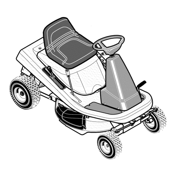
Mid-Engine Rider
= Maintenance
• Parts
13.5 HP. Electric Start
30" Mower / Mulcher
Hydrostatic
Drive
Model536.270282
CAUTION:
Before using this
product, read this manual
and follow all of its Safety
Rules and Operating
Instructions.
Manual del usario
Tractor cortacesped con motor
situado detras del asiento
Arranque electrico de 13,5 caballos
Cortacesped
/ trituradora de 76 cm.
Transmisibn
hidrostatica
Modelo 536.270282
PRECAUCION:
Antes de usar este
producto, lea este manual y siga
todas las reglas de seguridad
e
instrucciones
de operaci6n.
• Seguridad
• Operacibn
• Mantenimiento
• Piezas
Sears, Roebuck and Co., Hoffman Estates, IL. 60179 U.S.A.
F-040603L
www.sears.com/craftsman
Advertisement

Related Manuals for Craftsman 536.270282


Summary of Contents for Craftsman 536.270282
- Page 1 • Seguridad Modelo 536.270282 • Operacibn • Mantenimiento PRECAUCION: Antes de usar este • Piezas producto, lea este manual y siga todas las reglas de seguridad instrucciones de operaci6n. Sears, Roebuck and Co., Hoffman Estates, IL. 60179 U.S.A. F-040603L www.sears.com/craftsman...
- Page 2 ........REPAIR PARTS ......... LIMITED WARRANTY ON CRAFTSMAN RIDING EQUIPMENT For two (2) years from the date of purchase, if this Craftsman Riding Equipment is maintained, lubricated and tuned according to the instructions in the owner's manual, Sears will repair or replace...
- Page 3 Congratulations onyour p urchase ofa Craftsman Mid-Engine Rider. Ithasbeen designed, engineered andmanufactured Craftsman Mid-Engine Rider giveyou thebest p ossible dependability andperformance. Record in the space below the serial number and the date Ifyouexperience anyproblems youcannot easily r emedy, please of purchase of this unit.
- Page 4 SAFETY RULES Safe Operation Practices for Ride-on Mowers WARNING: This cutting machine is capable of amputating hands and feet and throwing objects. Failure to observe the following safety instructions could result in serious injury or death. General operation Data indicates that operators, age 60 years and above, are in-...
- Page 5 SAFETY RULES Never carry children or any passengers, even with the blades Stop and inspect the equipment if you strike an object. Repair, off. They may fall off and be seriously injured or interfere with if necessary, before restarting. the safe operation of the machine.
- Page 6 SAFETY RULES INTERNATIONAL PICTORIALS IMPORTANT: Some of the following pic- Flush Eyes immediately With Water. DANGER: No Step. torials are located on your unit or on Get Medical Help Fast. DANGER: Keep Feet And Hands literature supplied with the product. IMPORTANT: Read Owner's Manual...
- Page 7 PREPARATION PREPARATION Locate the two tear tabs at the top of the carton. Pull the tear tape no more than twelve inches at a time. Read and follow the preparation instructions for your mower. fasteners are in the parts bag. Do not discard any parts or material Re-grasp the tear tape next to the carton...
- Page 8 PREPARATION MAINTENANCE FREE BATTERY Use a 12 volt battery charger to charge the battery. Charge a rate of 6 amperes for one hour. If you do not have a battery IMPORTANT: Before attach battery cables to the charger, have a Sears or other qualified Service Center charge...
- Page 9 PREPARATION HOW TO ENGAGE THE TRANSMISSION To allow the unit to be pushed, the unit shipped with automatic drive disconnect in the PUSH POSITION. Before operating, the automatic drive disconnect must be set in the DRIVE POSITION. (Figure Automatic Drive Disconnect DRIVE POSITION The engine must be off.
- Page 10 OPERATION Ignition @ Stop Clutch / Brake (_Run Pedal (_) Start Attachment Clutch Parkiing Brake Speed Control Lever Lift Lever Throttle Control Lever Figure 3 The operation of any lawn mower can result in foreign objects thrown in the eyes, which can result in severe eye damage.
- Page 11 OPERATION HOW TO STOP THE UNIT electrical system operator presence system that Move the speed control lever to the NEUTRAL position. includes a sensor switch mounted in the seat. These components Set the parking brake. tell the electrical system if the operator is sitting on the seat.
- Page 12 OPERATION HOW TO USE THE ATTACHMENT CLUTCH Use the attachment clutch to engage the blade (Figure Before you start the engine, make sure the attachment clutch is in the DISENGAGE position. To rotate the blade, move the attachment clutch forward lock the blade in the ENGAGE position.
- Page 13 OPERATION HOW TO USE THE SPEED CONTROL LEVER The Hydrostatic Drive is very easy to operate. The drive system a a clutch/brake pedal on the left side (see Figure 9) and a speed control lever on the right side (see Figure 10).
- Page 14 OPERATION SPEED CONTROL LEVER POSITIONS SPEED The forward speed is controlled by the position of the speed control FUNCTION CONTROL THROTTLE LEVER lever. following chart provides functions along with POSITION positions of the speed control lever. Always operate the engine with the throttle control in the FAST...
- Page 15 OPERATION HOW TO INSTALL THE SIDE DISCHARGE ATTACHMENT Remove the two wingnuts (see Figure 12). connect the wire from the spark plug. Make sure the WARNING: To prevent the engine from starting, dis- Lift the mulcher cover. Mount the side discharge attachment attachment clutch is in the DISENGAGE position.
- Page 16 OPERATION BEFORE STARTING THE ENGINE CHECK THE OIL CAUTION: Alcohol blended fuels (called gasohol or using ethanol or methanol) can attract moisture which leads to NOTE: The engine was shipped from the factory filled with SAE separation and formation of acids during storage. Acidic gas 30 weight oil.
- Page 17 OPERATION HOW TO OPERATE WITH THE MOWER HOUSING WARNING: The mulch cover is a safety device. Do not CAUTION: Do not operate with the mower housing in the LEVEL ADJUSTMENT position. If you operate in the remove the mulch cover. The side discharge attach- LEVEL ADJUSTMENT position, the mower housing and ment forces...
- Page 18 OPERATION OPERATING TIPS Check the attachment clutch for correct adjustment. For the Before you make an inspection, adjustment (except for the car- blade(s) to disengage correctly, the adjustment must be cor- buretor) or repair, make sure the wire from the spark plug is dis- rect.
- Page 19 MAINTENANCE MAINTENANCE TABLE FIRST EVERY EVERY EVERY EACH BEFORE PROCEDURE HOURS HOURS HOURS HOURS STORAGE Blade, Inspect and Sharpen Battery, Check and Charge Lubrication Oil, Change Cooling System, Clean Muffler, Check Spark Plug, Check Spark Plug, Replace " GENERAL RECOMMENDATIONS The owner's responsibility is to maintain...
- Page 20 MAINTENANCE INSPECT BLADE Tightenthe nutthatholdsthe bladeto a torque of35foot pounds. WARNING: Before you inspect or remove the blade, disconnect the wire to the spark plug. If the blade its an object, stop the engine. Check the unit for damage. The blade has sharp edges.
- Page 21 MAINTENANCE MAINTENANCE FREE BATTERY HOW TO REMOVE THE BATTERY Clean the terminals and the ends of the cables with a wire brush. To charge or clean the battery, remove the battery from the unit as Install the battery. follows. To prevent corrosion, apply grease to the battery...
- Page 22 MAINTENANCE WHERE TO LUBRICATE _..%_ Apply grease with a brush to the areas shown. Lubricate the areas shown with engine oil. NOTE: Apply grease to the steering gear assembly. CAUTION: If the unit is operated in dry areas that have sand, use a dry graphite spray to lubricate the unit.
- Page 23 MAINTENANCE ENGINE HOW TO CHANGE THE OIL NOTE: Do not drain the oil from a cold engine. Before you drain HOW TO CHECK THE OIL the oil, let the engine run for several minutes. Make sure you do not get oil on the belts. NOTE: Do not check the level of the oil while...
- Page 24 MAINTENANCE HOW TO CLEAN THE AIR FILTERS Some engines have two filters, an outer foam filter around an inner 11. Assemble the air filters with the nut. paper filter. Clean the air filters every 50 hours. If you operate dirty conditions, service more often.
- Page 25 SERVICE AND ADJUSTMENT HOW TO ADJUST CHOKE THE REMOTE THROTTLE CONTROL For the best engine performance, set the remote throttle control as follows. FAST Remote Throttle Control Move the remote throttle control to the FAST position (see Figure 22). SLOW The hole in the governor control lever (located just behind gov- Figure 22...
- Page 26 SERVICE AND ADJUSTMENT HOW TO LEVEL THE MOWER HOUSING If the mower housing is level, the blade will cut easier and the lawn will look better. Level Ad Position WARNING: Before you make an inspection, adjust- Lift Lever ment, or repair to the unit, disconnect the wire to the spark plug.
- Page 27 SERVICE AND ADJUSTMENT HOW TO ADJUST THE ATTACHMENT CLUTCH Check the blade(s). Keep a sharp edge on the blade(s). A blade that is not sharp will cause the tips of the grass to become brown. ARNING: prevent injury, attachment clutch must operate correctly.
- Page 28 SERVICE AND ADJUSTMENT HOW TO REMOVE THE MOWER HOUSING HOW TO INSTALL THE MOWER HOUSING Move the attachment clutch to the DISENGAGE position. Push the mower housing under the right side of the unit. Move the lift lever to the level adjustment position (Figure 30).
- Page 29 SERVICE AND ADJUSTMENT HOW TO REPLACE THE MOTION DRIVE BELTS ENGINE DRIVE BELT REMOVAL Remove the mower housing. See the instructions on "How To Remove The Mower Housing". Set the rear hitch on a 10 to 12 inch block. The block must be high enough to raise the rear wheel...
- Page 30 SERVICE AND ADJUSTMENT HOW TO REPLACE THE MOWER DRIVE BELT Remove the mower housing. See the instructions on "How To Pull the belt retainer away from the idler pulley. Put the mow- Remove The Mower Housing". er drive belt around the idler pulley.
- Page 31 SERVICE AND ADJUSTMENT HOW TO ADJUST THE SPEED CONTROL LEVER WARNING: Before you make an inspection, adjust- Assemble the adjuster nut to the hydro actuator arm and secure with the hair pin. ment, or repair to the unit, disconnect the wire to the spark plug.
- Page 32 SERVICE AND ADJUSTMENT HOW TO INSTALL THE WHEELS If the wheels must be removed for service, make sure they installed as fellows. Front Wheel Make sure the valve stem is to the outside of the tractor. Slide the front wheel on the spindle (See Figure 40).
- Page 33 SERVICE AND ADJUSTMENT HOW TO REPLACE THE FUSE THE ENGINE If the fuse is blown, the engine will not start. The location of the fuse Clean the dirt and grass from the engine. is next to the battery. Remove the fuse and replace with a 15 amp.
- Page 34 TROUBLESHOOTING CHART engine Drain the fuel tank. Clean the fuel line. Replace the fuel filter. PROBLEM: will not start. Follow the steps, "How To Start The Engine" in this book. PROBLEM: A hot engine causes a decrease in power. Electric-Start Models: Clean the battery...
- Page 35 SEARS, ROEBUCK AND CO, Federal California Emission Control Systems Limited Warranty Small Off-Road Engines CALIFORNIA & US EPA EMISSION CONTROL WARRANTY must be presented of the date of sale to the original purchaser. The purchas- STATEMENT er shall pay any charges for making service calls and/or for transporting the products to and from the place where the inspection and/or warranty work The U.
- Page 36 7.Throughout the ECS Warranty Period, Sears, Roebuck and Co. s hall EMISSION-RELATED PARTS INCLUDE THE FOLLOWING: maintain asupply ofwarranted emission-related parts sufficient tomeet the 1. Carburetor Assembly and its Internal Components expected demand forsuch e mission-related parts. a) Fuel filter 8.Any Sears, Roebuck and Co.
- Page 37 SLOPE GUIDE Fold this page along dotted line indicated below. Hold page before you so that its left edge is vertically parallel to a tree trunk or other upright structure. Sight across the ..U_.oO_'__ fold in the direction of the hill or slope you want to measure. Compare the angle of the , i""-._._.._._'S...
- Page 38 MODEL 536.270282 REPAIR PARTS CHASSIS & HOOD • "/26 °0 F-O40603L...
- Page 39 MODEL 536.270282 REPAIR PARTS CHASSIS & HOOD Part No. Part No. Description Description 690566 Seat 26x263 Screw 1401027E201 Hood 1401110 Rod, Hood Prop 017x47 Washer 1401282 Spring, Seat Deck 1401297E701 1001054 Bolt, Wing Bracket, Prop Rod 26x201 Screw 002x53 Bolt, Carriage 15x116 1401036E701 Bracket, Hinge...
- Page 40 MODEL 536.270282 REPAIR PARTS STEERING "_ F-O40603L...
- Page 41 REPAIR PARTS MODEL 536.270282 STEERING Part No. Description Part No. Description 095185 Wheel, Steering 01x146 Bolt, Hex 711326 Cap, Steering (Black) 011x23 E-Ring, Retainer 1401067 Console, High (Black) 030x35 Pin, Cotter 26x250 Screw 094131 Retainer, Spring 1401090 Bearing, Upper Steering 1401046E701 Rack, Steering 1401100...
- Page 42 MODEL 536.270282 REPAIR PARTS MOTION DRIVE 11 i ÷ F-O40603L...
- Page 43 MODEL 536.270282 REPAIR PARTS MOTION DRIVE Part No. Description Part No. Description 1401104 Guide, Belt-Short Engine 091309 Gasket, Muffler 1401032E701 Bracket, Lift Pivot 091271 Muffler 1401307 Z Rod, Shift Link 092378 Lock, Muffler Screw 092697 Grip 01x134 Bolt, Hex 1401148 Nut, Adjusting 1401207 Shield, Heat...
- Page 44 MODEL 536.270282 REPAIR PARTS MOWER HOUSING SUSPENSION F-O40603L...
- Page 45 MODEL 536.270282 REPAIR PARTS MOWER HOUSING SUSPENSION Part No. Description Part No. Description 092697 17x206 Washer Grip, Lift Lever 1401117 Lever, Lift 015x79 Nut, Flange 165x154 Spring, Extension 015x84 Nut, Flange 094137 Pad, Friction 1401147 Spring, Leaf 017x45 Washer 1401040E701 Hanger, Front 095004 Wingnut...
- Page 46 MODEL 536.270282 REPAIR PARTS MOWER HOUSING F-O40603L...
- Page 47 REPAIR PARTS MODEL 536.270282 MOWER HOUSING Part No. Description Part No. Description 009x42 Bolt, Shoulder 37x111 Belt, Blade Drive 030x20 Pin, Cotter 1401092 Pulley, Input 1401185E701 Arm Assembly, Brake 15x140 Locknut 1401119 Link, Idler Arm 015x98 Nut, Flange 0025x7 Bolt 1401252 Pulley, Idler 1401052E701...
- Page 48 MODEL 536.270282 REPAIR PARTS ELECTRICAL SYSTEM _15AMP FUSE IGNITIONSWITCH | CLUTCH DRAKE ORANGE SWITCH RUN11 B+L DISENGAGED UN21 ..(PEDAL UP) ARTI SOLENOID IGNI_ON SVvlTCH _EWED FROM SPARK ARMATURE PLUG BLACK SEATSWRCH YELLOW ® SEATSW_CH UNOCCU_ED BACK BLACK ORANGE GRAPHIC OUTPUT REPRESENTATION TEST...
- Page 49 MODEL 536.270282 REPAIR PARTS ELECTRICAL SYSTEM Part Description 250x115 Harness, Chassis Wire 1401149 Switch, Ignition 327349 Key, Ignition 1001575 Switch, Limit 302031 Fuse 407078 Holder, Fuse 094613 Solenoid 26x229 Screw, Mounting 15x116 Locknut 024x37 Cable, Battery Ground Screw, Ground Cable 092739 Battery 002x82...
- Page 50 NO STEP (Mower Deck - Left Side) 48x5211 Clutch / Brake ( Footrest -Left Side) 48x236 Cut Finger (Mower Deck -Right Side) 48x5206 Craftsman 13.5 (Hood -Right Side) 48x5207 Craftsman 13.5 (Hood -Left Side) 44x5214 Deck Level Position / ONLY (Seat Deck -Left Side) 48x5057...
- Page 51 NOTES F-O40603L...
- Page 52 MODEL 536.270282 ENGINE 28R707-1120-E1 I 1019 KIT-LABEL ILOS8 OWNER'S MANUAL 307_ 718 I! 322A 3081 13A_ 733_ 810_ 27 c_ F-O40603L...
- Page 53 MODEL 536.270282 ENGINE 28R707-1120-E1 REF. PART PART REF. PART DESCRIPTION DESCRIPTION DESCRIPTION 496413 Note ..691003 Screw Cylinder Assembly 399265 Kit-Bushing/Seal 696404 Ring Set (Cylinder Shield) 491490 (Magneto Side) (.010" Oversize) Cover-Cylinder Head *391086 Seal-Oil 696405 Ring Set (Used Before Code Date (.020"...
- Page 54 MODEL 536.270282 ENGINE 28R707-1120-E1 1251 13311o4/ 95 _ 1270 1091_ 106_ 108A_ I _30A_ 987_6_ 634A_ 2271 404 _ 267 _ 562_ 4741 1119_ F-O40603L...
- Page 55 MODEL 536.270282 ENGINE 28R707-1120-E1 REF. PART PART REF. PART DESCRIPTION DESCRIPTION DESCRIPTION 691711 Manifold-intake 494885 Kit-Throttle Shaft 691061 Screw 51 e.692284 Gasket-Intake 131A 494379 Kit-Throttle Shaft (Magneto Armature) 51A *G272554 Gasket-Intake 494381 Float-Carburetor 691691 Washer 691098 Stud 137 e_,281165 Gasket-Float Bowl (Governor Crank)
- Page 56 MODEL 536.270282 ENGIN E 28R707-1120-E1 11036 LABEL-EMISSION I 8471 601X 167 _ 363_ . _o_ 726 ___ 344 % 668A 1850 733 _ 75 _ 305A 1070_ 1005 F-O40603L...
- Page 57 MODEL 536.270282 ENGINE 28R707-1120-E1 REF. PART REF. PART REF. PART DESCRIPTION DESCRIPTION DESCRIPTION 691328 Tube-Breather 692198 Screw (Starter Drive Cover) 693557 691658 Screw Flywheel (Blower Housing) 690456 305A 692127 Screw Guard-Flywheel (Crankshaft Extension) 691748 693713 Gear-Pinion Screen-Rotating (Blower Housing) 691655 19203 Screw Flywheel...
- Page 58 MODEL 536.270282 ENGINE 28R707-1120-E1 358 ENGINE GASKET 524_ 842 _/-_ 10514 797A @ 121 CARBURETOR OVERHAUL 106 _ 276 _=_ 987 _o_ 503<_ 634_ lO5_ 104/ 634A_ 697_ 801A_ 977 CARBURETOR GASKET 544A_ 803A_ 1095 VALVE GASKET 783A_ 802AI 1083 311A 513@ 108__...
- Page 59 MODEL 536.270282 ENGINE 28R707-1120-E1 REF. PART PART REF. PART DESCRIPTION DESCRIPTION DESCRIPTION 276 e.692255 *391086 Seal-Oil Washer-Sealing (Drive Cap) 693551 Motor-Starter (Magneto Side) 691224 Clip-Wire 309A Motor-Starter 693713 Gear-Pinion 7 0*271866 Gasket-Cylinder Head ¢_.27803 Gasket-Breather 783A 693059 Gear-Pinion (For Replacement 693167 *692226 Gasket-Crankcase...
- Page 60 MODEL 536.270282 /_:l !_!. _209 ..210A F-O40603L...
- Page 61 MODEL 536.270282 PEERLESS HYDRO 2000-2000-022 Pa_ No. Description PaX No. Description 792154 Oil Fill Plug 772152A Cover RH (Mach) Oil Seal .750 788088A 770136 Case RH (Cast) Screw 1/4-28 x .490 792193 Counter Shaft 776441 Screw 1/4-28 x .406 103A 792205 778263 Spur Gear 11T...
- Page 62 INDEX Mulcher, Operation, 18 Mulcher Cover, Remove, 15 Adjustments Filter, Air, 24 Clutch, Fuel, Type, Mower Housing, Level, 26 Fuse, Air Screen, Change, Attachments, Check, 16, 23 Type, Automatic Drive Disconnect, Operation, Operation Ignition Switch, Location, Attachments, Automatic Drive Disconnect, Clutch/Brake Pedal, Battery...
- Page 63 Este cargo no ser& aplicado si Ileva el Craftsman producto a un Centro de Servicio Sears autorizado. Para Iocalizar el Centro de Servicio Sears autorizado, mas cercano a usted,...
- Page 64 Felicidades por su compra de este Tractor cortacesped Tractor cortacesped con motor motor situado detras del asiento de Craftsman. Su unidad ha sido situado detras del asiento disefiada y fabricada para darle los mejores resultados en Io que Anote en los espacios correspondientes,...
- Page 65 REGLAS DE SEGURIDAD Pr&cticas de operaci6n segura para vehiculos autoportados Basadas en las recomendaciones del Instituto de Est_ndares Nacionales de Estados Unidos de America PRECAUCION: Esta m_quina cortadora es capaz de amputar manos y pies y de lanzar objetos con mucha fuerza. No respetar las instrucciones de seguridad a continuaci6n podria resultar en lesiones graves o la muerte del operador o...
- Page 66 REGLAS DE SEGURIDAD Nunca arranque el motor ni Io deje en marcha dentro de un Evite tener que arrancar el motor o pararlo en una cuesta. recinto cerrado. Si los neumaticos pierden traccion, desembrague la cuchi- Ila(s) y continQe despacio directamente hacia el pie de la...
- Page 67 REGLAS DE SEGURIDAD SiMBOLOS INTERNACIONALES El acido sulfOrico puede causar ceguera o PELIGRO: No pisar. quemaduras graves. PELIGRO: Mantenga los pies y las manos IMPORTANTE: Los siguientes simbolos Limpie los ojos inmediatamente con agua. a una distancia segura de Ia cuchilla en est_n ubicados en su unidad...
- Page 68 PREPARACION PREPARACION Ubique las dos lengOetas de separacion ubicadas en la parte superior de la caja de carton. Lea y siga las instrucciones de preparaci6n para su cortacesped. Jale la cinta de separacion por m&s de doce pulgadas a la vez. Todos los sujetadores se encuentran...
- Page 69 PREPARACION BATERiA LIBRE DE MANTENIMIENTO un cargador de baterias de 12 voltios para cargar bateria. C&rguela a una velocidad de 6 amperios por hora. Si IMPORTANTE. Antes de conectar los cables de bateria a la no tiene un cargador, Ileve la bateria a un centro autorizado bateria, compruebe la fecha de la misma.
- Page 70 PREPARACION COMO CONECTAR LA TRANSMISION NOTA: En clima frio, la alta viscosidad del aceite transmisi6n har_ que la unidad sea dificil de empujar. Para poder empujarla, la unidad fue enviada de f&brica con la barra de desconexi6n autom_tica de la transmisi6n en la POSICION DE EMPUJE.
- Page 71 OPERACION de encendido Interruptor Stop (_Run Pedal de embrague y freno Start Embrague de aditamento Palanca de freno de estacionamiento Palanca de control de velocidad Palancade elevacion Palanca de control de aceteracidn Figura 45 La operaci6n de cualquier cortadora de c_sped puede causar el lanzamiento...
- Page 72 OPERACION COMO DETENER LA UNIDAD El sistema electrico tiene un sistema que detecta la presencia Mueva la palanca de control de velocidad a la posicion NEU- TRO. operador, el cual incluye un sensor conectado al asiento. Estos componentes le indican al sistema electrico si el operador...
- Page 73 OPERACION COMO USAR EL EMBRAGUE DE ADITAMENTO El embrague de aditamentos se usa para enganchar la cuchifla (Figura 48). Antes de arrancar el motor, asegt_rese de que el embrague aditamentos este en la posici6n DESEMBRAGUE Para que la cuchilla empiece a girar, mueva el embrague aditamentos...
- Page 74 OPERACION COMO USAR LA PALANCA DE CONTROL DE VELOCIDADES La transmision hidrost&tica es muy f&cil de operar. El sistema transmisi6n tiene un pedal de embrague / freno en el lado izquierdo Pedal de (Figura 51) y una palanca de control de velocidades y direccion embrague/freno...
- Page 75 OPERACION POSICIONES DE LA PALANCA FUNCION POSICIONDE CONTROL DE DE CONTROL DE VELOCIDADES ACELERACION LA PALANCA DE CONTROLDE La velocidad de avance se controla por la posici6n de la palanca VELOCIDADES control velocidades. El cuadro siguiente incluye funciones junto con las posiciones correspondientes de la palanca de control...
- Page 76 OPERACIC)N COMO DE INSTALAR EL ADITAMENTO PARA DESCARGA LATERAL Levante la cubierta para trituradora. Monte el aditamento desconecte el cable de la bujia. El embrague del adi- descarga lateral en los mismo pernos que sujetaban la cu- ADVERTENCIA. Para evitar que el motor arranque, tamento tiene que estar en la posici6n de DESEM- bierta para trituradora.
- Page 77 OPERACIC)N ANTES DE ENCENDER EL MOTOR REVISE EL ACEITE PRECAUCION: combustibles mezclados alcohol (llamados gasohol o aquellos usan etanol o metanol), NOTA: La unidad fue enviada desde la f_brica con el motor Ileno pueden atraer humedad Io cual causa la separaci6n y formaci6n de aceite SAE, peso 30.
- Page 78 OPERACION COM0 0PERAR, CON EL CARTER DE LA CORTADORA ADVERTENCIA: La cubierta para trituradora Mueva el acelerador a la posicion LENTO. dispositivo de seguridad. No la quite. El deflector Mueva el embrague de aditamento a la posicion de ENGAN- fuerza el material cortado hacia la tierra. Mant_ngalo siempre en la posici6n hacia abajo.
- Page 79 OPERACION SUGERENCIAS PARA LA OPERACION Examine el embrague de aditamentos para el ajuste correcto. AsegQrese de que el cable de interruptor del asiento este co- Para que la cuchilla (o cuchillas) desenganche correctamente, nectado. Si el cable no est& conectado, no se encender&...
- Page 80 MANTENIMIENTO TABLA DE MANTENIMIENTO Primeras Cada Cada Cada Cada Antes de PROCEDIMIENTO horas horas horas horas guardar Cuchilla, Inspeccionar y Afilar Bateria, Revisar y Cargar Lubricacion Aceite, Cambiar Silenciador, Revisar Bujia, Revisar Bujia, Reemplazar " RECOMENDACIONES GENERALES El propietario es responsable de dar mantenimiento a este pro- Siga las indicaciones...
- Page 81 MANTENIMIENTO INSPECCION DE LA CUCHILLA tuerca que sujeta la cuchilla. Una tuerca o cuchilla DVERTENClA: Mantenga siempre apretada floja puede causar un accidente. cuchilla, desconecte el cable de la bujia. Si la cu- ADVERTENCIA: Antes de inspeccionar o sacar Apriete la tuerca que sujeta la cuchilla...
- Page 82 MANTENIMIENTO BATERiA LIBRE DE MANTENIMIENTO COMO DESMONTAR LA BATER{A Limpie los bornes y los extremos de los cables con un cepillo para cables. Si necesita cambiar o limpiar la bateria, desmontela de la siguiente Instale la bateria. manera. Aplique grasa a los bornes para prevenir la corrosi6n.
- Page 83 MANTENIMIENTO DONDE LUBRICAR _,%_ Lubrique con aceite de motor las areas mostra- Aplique grasa con un cepillo alas areas mostra- das. das. NOTA: Aplique grasa ensamblado mecanismo direcci6n. PREOAUCION: Si la unidad se opera en _reas _ridas donde hay arena, utilice polvo de grafito...
- Page 84 MANTENIMIENTO MOTOR COMO CAMBIAR EL ACEITE NOTA: No drene aceite de un motor frio. Antes de drenar el COMO REVISAR EL ACEITE aceite, deje que el motor funcione durante varios minutos. Asegt_rese de no derramar aceite en las correas. NOTA: No revise el nivel del aceite...
- Page 85 MANTENIMIENTO COMO LIMPIAR LOS FILTROS DE AIRE Algunos motores tienen dos filtros, un filtro de goma espuma 10. Si el filtro de papel esta muy sucio, reempl&celo. exterior alrededor de un flltro de papel interno. Limpie los filtros de 11. Ensamble los filtros de aire con la tuerca.
- Page 86 SERVICIO Y AJUSTE COMO AJUSTAR CONTROL DE ACELERACION REMOTO Para obtener un rendimiento optimo del motor, ajuste el control aceleraci6n remoto de la siguiente manera. Control de aceleraci6n Mueva la palanca del control de aceleraci6n remoto a la po- remoto sici6n R/kPIDO (Figura...
- Page 87 SERVICIO Y AJUSTE COMO NIVELAR EL CARTER Para que la cuchilla corte con facilidad y el cesped tenga mejor aspecto es necesario que el c&rter del cortacesped este nivelado. PosiciOn de ajuste de nivel ADVERTENCIA. Antes de inspeccionar, ajustar o re- Palanca de e;_aci6n _ parar la unidad,...
- Page 88 SERVICIO Y AJUSTE COMO AJUSTAR EL EMBRAGUEDE ADITAMENTO Revise las cuchillas. AsegQrese de que esten bien afiladas. no Io est&n, las puntas del cesped se secaran. ADVERTENCIA: El embrague de aditamento tiene que funcionar correctamente para evitar lesiones. Si ann asi el corte no mejora, cambie la correa...
- Page 89 SERVICIO Y AJUSTE COMO DESMONTAR EL CARTER COMO INSTALAR EL CARTER Empuje el carter por debajo del lado derecho de la unidad. Mueva el embrague de aditamento a la posicion de DESEM- BRAGUE. Ponga la correa de transmisiOn alrededor de la polea doble. El lado en forma de "V"...
- Page 90 SERVICIO Y AJUSTE COMO REEMPLAZAR CORREA DE PROPULSION REMOCION DE LA CORREA PROPULSION MOTOR Desmonte carter cortacesped. Consulte instrucciones en la seccion "Como desmontar el c&rter cortacesped". Coloque el enganche trasero sobre un bloque de 10 a 12 pulgadas. El bloque debe ser suficientemente alto...
- Page 91 SERVICIO Y AJUSTE COMO CAMBIAR LA CORREA DE TRANSMISION DEL CORTAC¢:SPED Desmonte el c&rter del cortacesped. Consulte "Come desmon- Separe el retenedor de la correa de la polea tensora. Colo- tar el c&rter". que la correa de transmisi6n alrededor de la polea tensora.
- Page 92 SERVICIO Y AJUSTE COMO AJUSTAR LA PALANCA Si la unidad se movia lentamente hacia atr&s cuando la palan- DE CONTROL DE VELOCIDADES ca de control de velocidades estaba en la posici6n NEUTRO, entonces gire la tuerca ajustable hacia la izquierda (hacia atras), una o dos vueltas.
- Page 93 SERVICIO Y AJUSTE COMO INSTALAR LAS RUEDAS Chaveta Si necesita sacar las ruedas, vuelva a instalarlas de la siguiente manera. Tapacubos Arandela Arandela Rueda delantera El v_stago de v_lvula tiene que quedar hacia la parte exterior del tractor. Deslice la rueda delantera en la mangi.ieta.
- Page 94 SERVICIO Y AJUSTE COMO REEMPLAZAR EL FUSIBLE LUBRICACION DE LA UNIDAD Si el fusible esta fundido, no se encender& el motor. La ubicaci6n Vea las instrucciones sobre "D6nde lubricar" en la secci6n de del fusible est& al lado de la bateria. Quite el fusible y reemplacelo Mantenimiento.
- Page 95 TABLA DE LOCALIZACION DE AVERIAS PROBLEMA: El motor no se enciende. Ajuste el acelerador. Siga los pasos de "C6mo encender el motor" en este manual. Drene el tanque de combustible. Limpie la linea de combusti- ble. Reemplace el filtro de combustible. Limpie los bornes de la bateria.
- Page 96 SEARS, ROEBUCK AND CO. Garantia limitada de cumplimiento con el Sistema Federal de control de emisiones y con el sistema de control de emisiones del Estado de California Motores peque_os no aptos para carretera (off-road) NOTA IMPORTANTE CONTROL DE EMISIONES DE CALIFORNIA Y DE LA AGENCIA...
- Page 97 2.Cualquier parte garantizada yrelacionada con emisiones que est6 e speci- empei_o decualquier mantenimiento ocambio delaGarantia SCE, lacual ficada sdlo para i nspecciones regulares conforme a!Manual del Propietario seproporcionara sin cargo alguno para e lpropietario. Dicho uso no reducira debera estar garantizada por e lPeriodo delaGarantia SCE.
- Page 98 GUIA DE INCLINACION Doble esta hoja a Io largo de la linea de puntos indicada mas abajo. Sostenga la hoja frente a usted de manera que el borde izquierdo quede paralelo al tronco de un arbol u otra es- tructura erecta.
- Page 99 INDICE Inspecci6n, Parachispas, Preparaci6n, Aceite Rejilla parachispas, Silenciador, Cambiar, Desconexi6n autom&tica, Operacion, 70, Sistema de enfriamiento, Revisar, 77, 84 Tipo, 77 Aditamento para descarga lateral, Instalar, Operacion Embrague Aditamentos, Aditamentos, Ajustar, Arrancar el motor, Ajustes Revisar, Boton de control de aceleracion, Carter, Nivelar, Carter...
- Page 100 Your Home For repair-in your home-of all major brand appliances, lawn and garden equipment, or heating and cooling systems, no matter who made it, no matter who sold it! For the replacement parts, accessories owner's manuals that you need to do-it-yourself. For Sears professional installation of home appliances...