Table of Contents
Advertisement
Quick Links
Advertisement
Table of Contents

Related Manuals for GE PI-450


Summary of Contents for GE PI-450
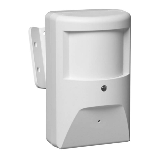
- Page 1 PI-450/950 PIR Camera...
- Page 2 © 2003 Kalatel, a GE Interlogix company All Rights Reserved. Any GE Interlogix, Kalatel division, software supplied with GE Interlogix, Kalatel division, products is proprietary and furnished under license and can be used or copied only in accordance with the terms of such license.
-
Page 3: Before You Begin
For assistance in installing, operating, maintaining, and troubleshooting this product, refer to this document and any other documentation provided. If you still have questions, contact Kalatel Technical Support: GE Interlogix, Kalatel division Call: 800-469-1676 Fax: 541-752-9096 Note: You should be at the equipment, ready with details before calling Technical Support. -
Page 4: Mounting The Unit
PI-450/950 PIR Camera Installation Instructions OUNTING THE Remove the cover (see Figure 1). Unplug the cable. Detach the wires by loosening the terminal screws. Remove the mounting bracket by removing the screw and washer (see Figure 2). Figure 1. Removing the cover Figure 2. - Page 5 Installation Instructions PI-450/950 PIR Camera Note: Mount the camera with a 3/8-inch (1 cm) clearance from the ceiling. For optimal PIR coverage using the standard lens, mount the PIR 7 feet (2 m) above the floor. You may have to compromise to get good PIR and camera coverage. Mark the mounting holes on the mounting surface (see Figure 3).
- Page 6 PI-450/950 PIR Camera Installation Instructions ONNECTIONS See Figure 4. Video Not used Video ground LED enable/disable jumper Not used Tamper switch Not used Tamper Ground Tamper 12 VDC Normally open Incoming cable harness Common Interconnect to camera Normally closed Figure 4. Circuit board connections Note: Connections can be made using the supplied cable harness ( ) or the six-pin terminal strip (...
- Page 7 Installation Instructions PI-450/950 PIR Camera LED E NABLE ISABLE UMPER Enabled Disabled ENSITY Figure 5 shows the pattern produced when the PIR is mounted flat against the wall at a height of 7 feet (2 m). The pattern will vary when the PIR is angled to get the best camera view.
-
Page 8: Camera Views
PI-450/950 PIR Camera Installation Instructions AMERA IEWS 3/8 in. 54º vertical 18º 69º horizontal Figure 6. Camera views with a 3.6 mm lens 3/8 in. 36º vertical 18º 48º horizontal Figure 7. Camera views with a 5 mm lens 1036380B / February 2003... - Page 9 Installation Instructions PI-450/950 PIR Camera PIR S PECIFICATIONS Electrical Voltage 12 VDC Current 14 mA typical 20 mA max Maximum loop rating 16 VDC, 50 mA Alarm output Failsafe contacts-form C N/C N/O Alarm duration 3.2 sec (± 0.5 sec) Cover tamper contacts Environmental Operating...
-
Page 10: Specifications
PI-450/950 PIR Camera Installation Instructions AMERA PECIFICATIONS PI-450 PI-950 Image sensor 1/3-in. interline transfer 1/3-in. interline transfer Lens options 3.6-mm pinhole standard 3.6-mm pinhole standard 5-mm pinhole option 5-mm pinhole option Scanning system 2:1 interlace, EIA 2:1 interlace, NTSC 525 lines/ 60 fields 525 lines / 60 fields option: CCIR 625/50 option: PAL 625/50...