Table of Contents
Advertisement
Advertisement
Table of Contents

Related Manuals for Asus Z77-A


Summary of Contents for Asus Z77-A
- Page 1 Z77-A...
- Page 2 Product warranty or service will not be extended if: (1) the product is repaired, modified or altered, unless such repair, modification of alteration is authorized in writing by ASUS; or (2) the serial number of the product is defaced or missing.
-
Page 3: Table Of Contents
Contents Safety information ..................vi About this guide ..................vii Z77-A specifications summary ..............ix Package contents ..................xii Product introduction Product highlights ............... 1-1 Before you proceed ..............1-4 Motherboard overview ..............1-5 1.3.1 Placement direction ............1-5 1.3.2 Screw holes .............. - Page 4 Managing and updating your BIOS ..........2-1 2.1.1 ASUS Update utility ............2-1 2.1.2 ASUS EZ Flash 2 ............2-2 2.1.3 ASUS CrashFree BIOS 3 utility ........2-3 2.1.4 ASUS BIOS Updater ............2-4 BIOS setup program ..............2-7 Main menu .................. 2-11 2.3.1 System Language [English] ...........2-11...
- Page 5 2.7.11 Boot Option Priorities ............ 2-39 2.7.12 Boot Override ..............2-39 Tools menu ................. 2-40 2.8.1 ASUS EZ Flash 2 Utility ..........2-40 2.8.2 ASUS O.C. Profile ............2-40 2.8.3 ASUS SPD Information ..........2-40 Exit menu ..................2-41 Appendices Notices .......................A-1...
-
Page 6: Safety Information
Safety information Electrical safety • To prevent electric shock hazard, disconnect the power cable from the electric outlet before relocating the system. • When adding or removing devices to or from the system, ensure that the power cables for the devices are unplugged before the signal cables are connected. If possible, disconnect all power cables from the existing system before you add a device. -
Page 7: About This Guide
Refer to the following sources for additional information and for product and software updates. ASUS websites The ASUS website provides updated information on ASUS hardware and software products. Refer to the ASUS contact information. Optional documentation Your product package may include optional documentation, such as warranty flyers, that may have been added by your dealer. -
Page 8: Conventions Used In This Guide
Conventions used in this guide To ensure that you perform certain tasks properly, take note of the following symbols used throughout this manual. DANGER/WARNING: Information to prevent injury to yourself when trying to complete a task. CAUTION: Information to prevent damage to the components when trying to complete a task IMPORTANT: Instructions that you MUST follow to complete a task . -
Page 9: Z77-A Specifications Summary
1866(O.C.) / 1600 / 1333 1066MHz, non-ECC, un-buffered memory Dual-channel memory architecture Supports Intel Extreme Memory profile (XMP) • Refer to http://www.asus.com for the latest Memory QVL (Qualified Vendors List). • Hyper DIMM support is subject to the physical characteristics of individual CPUs. - Page 10 - 4 x USB 3.0 / 2.0 ports (2 ports at the mid-board and 2 ports at the rear panel) - 8 x USB 2.0 (4 ports at the mid-board and 4 ports at the rear panel) - Supports ASUS USB 3.0 Boost UASP Mode* *USB 3.0 ports only support Windows 7™ or later versions. UASP standards ®...
- Page 11 BIOS 64 Mb Flash ROM, UEFI AMI BIOS, PnP, DMI2.0, WfM2.0, SM BIOS 2.7, ACPI 4.0a, Multi-language BIOS, ASUS EZ Flash 2, ASUS CrashFree BIOS 3, F12 PrintScreen, F3 Shotcut Function and ASUS DRAM SPD (Serial Presence Detect) memory information Manageability WfM 2.0, DMI 2.0, WOL by PME, WOR by PME, PXE...
-
Page 12: Package Contents
Package contents Check your motherboard package for the following items. Z77-A 2 x Serial ATA 6.0 Gb/s ASUS Z77-A motherboard cables 1 x I/O Shield User Guide Support DVD • If any of the above items is damaged or missing, contact your retailer. -
Page 13: Product Introduction
Complete USB 3.0 Integration ASUS facilitates strategic USB 3.0 accessibility for both the front and rear panel - 4 USB 3.0 ports in total. Experience the latest plug & play connectivity at speeds up to 10 times faster than USB 2.0. -
Page 14: Intel Smart Response Technology
Smart Response Technology ® Intel Smart Response Technology, an important part of Green ASUS eco-friendly computing, ® reduces load and wait time, eliminates unecessary hard drive spin thus lowering power usage, and uses an installed SSD (requires 18.6 GB available space) as a cache for frequently accessed data or applications. - Page 15 This motherboard uses all high-quality conductive polymer capacitors for durability, improved lifespan, and enhanced thermal capacity. ErP ready This motherboard is European Union´s Energy-related Products (ErP) ready. ErP requires products to meet certain energy efficiency requirements with regard to energy usage. ASUS Z77-A...
-
Page 16: Before You Proceed
ON, in sleep mode, or in soft-off mode. This is a reminder that you should shut down the system and unplug the power cable before removing or plugging in any motherboard component. The illustration below shows the location of the onboard LED. SB_PWR Z77-A Standby Power Powered Off Z77-A Onboard LED Chapter 1: Product introduction... -
Page 17: Motherboard Overview
Screw holes Place six screws into the holes indicated by circles to secure the motherboard to the chassis. DO NOT overtighten the screws! Doing so can damage the motherboard. Place this side towards the rear of the chassis. Z77-A ASUS Z77-A... -
Page 18: Motherboard Layout
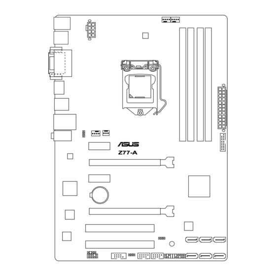
1.3.3 Motherboard layout 21.3cm(8.4in) CPU_FAN KBMS CHA_FAN2 DIGI USB34 +VRM EATX12V HDMI USB3_12 LAN_USB12 AUDIO CHA_FAN1 PWR_FAN PCIEX1_1 Z77-A 8111F PCIEX16_1 PCIEX1_2 Intel ® 1083 BATTERY PCIEX16_2 Super PCI1 BIOS USBPWF PCI2 SATA3G_3 SATA3G_2 ZSATA3G_1 SB_PWR SPDIF_OUT USB78 USB56 SATA3G_4... -
Page 19: Layout Contents
This motherboard comes with a LGA1155 socket designed for 2 generation Core™ i7/i5/i3, Pentium ® , and Celeron ® processors. The LGA1156 CPU is incompatible with the LGA1155 socket. DO NOT install a LGA1156 CPU on the LGA1155 socket. Z77-A Z77-A CPU socket LGA1155 ASUS Z77-A... -
Page 20: Cpu Installation
1.4.1 CPU installation The LGA1156 CPU is incompatible with the LGA1155 socket. DO NOT install a LGA1156 CPU on the LGA1155 socket. Chapter 1: Product introduction... -
Page 21: Cpu Heatsink And Fan Assembly Installation
1.4.2 CPU heatsink and fan assembly installation Apply the Thermal Interface Material to the CPU heatsink and CPU before you install the heatsink and fan if necessary. To install the CPU heatsink and fan assembly ASUS Z77-A... - Page 22 To uninstall the CPU heatsink and fan assembly Chapter 1: Product introduction 1-10...
-
Page 23: System Memory
The figure illustrates the location of the DDR3 DIMM sockets: Z77-A Z77-A 240-pin DDR3 DIMM sockets Recommended memory configurations We recommend that you install the memory modules from the blue slots for better overclocking ability. -
Page 24: Memory Configurations
• For system stability, use a more efficient memory cooling system to support a full memory load (4 DIMMs) or overclocking condition. Visit the ASUS website for the latest QVL. Z77-A Series Motherboard Qualified Vendors Lists (QVL) DDR3 2400MHz capability... - Page 25 KHX2000C9AD3T1K2/ KINGSTON 4GB(2 x 2GB) 1.65V • • • 4GX(XMP) KHX2000C9AD3W1K3/ KINGSTON 6GB(3x 2GB ) 1.65V • • 6GX(XMP) KHX2000C9AD3T1K3/ KINGSTON 6GB(3x 2GB ) 1.65V • • 6GX(XMP) Transcend TX2000KLN-8GK(XMP) 8GB(2 x 4GB) 1.6V • • • ASUS Z77-A 1-13...
- Page 26 DDR3 1866MHz capability DIMM socket support (Optional) S S / C h i p Chip Vendors Part No. Size Timing Voltage Brand 1 DIMM 2 DIMMs 4 DIMMs CORSAIR CMT4GX3M2A1866C9(XMP) 4GB(2 x 2GB) DS 9-9-9-24 1.65V • • • CORSAIR CMT6GX3MA1866C9(XMP) 6GB(3 x 2GB) DS 9-9-9-24...
- Page 27 TW3X4G1333C9D G 9-9-9-24 1.50V • • • (2 x 2GB) 256MBDCJ CORSAIR CM3X4GA1333C9N2 CORSAIR 9-9-9-24 - • • • GELC0401136 CORSAIR CMX4GX3M1A1333C9 9-9-9-24 1.50V • • • CORSAIR CMD8GX3M4A1333C7 7-7-7-20 1.60V • • • (4 x 2GB) ASUS Z77-A 1-15...
- Page 28 D I M M s o c k e t s u p p o r t S S / (Optional) Vendors Part No. Size Chip Brand Chip NO. Timing Voltage 1 DIMM 2 DIMMs 4 DIMMs Crucial CT12864BA1339.8FF Micron 9FF22D9KPT •...
- Page 29 • 138EY TMS2GB364D081- TAKEMS 7-7-7-20 1.5V • • 107EY TMS2GB364D081- TAKEMS 8-8-8-24 1.5V • • 138EY TMS2GB364D082- TAKEMS 8-8-8-24 1.5V • • 138EW UMAX E41302GP0-73BDB UMAX U2S24D30TP-13 • • • WINTEC 3WVS31333-2G-CNR AMPO AM3420803-13H • • • ASUS Z77-A 1-17...
- Page 30 Hyper DIMM support is subject to the physical characteristics of individual CPUs. Load the X.M.P. or D.O.C.P. settings in the BIOS for the hyper DIMM support. • Visit the ASUS website for the latest QVL. Chapter 1: Product introduction 1-18...
-
Page 31: Installing A Dimm
1.5.3 Installing a DIMM To remove a DIMM ASUS Z77-A 1-19... -
Page 32: Expansion Slots
Expansion slots Unplug the power cord before adding or removing expansion cards. Failure to do so may cause you physical injury and damage motherboard components. Z77-A Slot No. Slot Description PCIe 2.0 x1_1 slot PCIe 3.0/2.0 x16_1 slot [blue] (at 16x mode) PCIe 2.0 x1_2 slot... -
Page 33: Irq Assignments For This Motherboard
– shared – – – – RTL8111F shared – – – – – – – PCI Slot 1 – shared – – – – – – PCI Slot 2 – – shared – – – – – ASUS Z77-A 1-21... -
Page 34: Jumpers
CLRTC Normal Clear RTC (Default) Z77-A Clear RTC RAM To erase the RTC RAM: Turn OFF the computer and unplug the power cord. Move the jumper cap from pins 1-2 (default) to pins 2-3. Keep the cap on pins 2-3 for about 5~10 seconds, then move the cap back to pins 1-2. - Page 35 This feature requires an ATX power supply that can supply at least 1A on the +5VSB lead, and a corresponding setting in the BIOS. KB_USBPWB Z77-A +5VSB (Default) Z77-A Keyboard and USB device wake up ASUS Z77-A 1-23...
-
Page 36: Connectors
Connectors 1.8.1 Rear panel ports PS/2 Mouse port (green). This port is for a PS/2 mouse. Video Graphics Adapter (VGA) port. This 15-pin port is for a VGA monitor or other VGA-compatible devices. LAN (RJ-45) port. This port allows Gigabit connection to a Local Area Network (LAN) through a network hub. - Page 37 RGB signal to CRT and isn’t compatible with DVI-I USB 2.0 ports 3 and 4. These two 4-pin Universal Serial Bus (USB) ports are for USB 2.0/1.1 devices. PS/2 Keyboard port (purple). This port is for a PS/2 keyboard. ASUS Z77-A 1-25...
-
Page 38: Internal Connectors
These are not jumpers! DO NOT place jumper caps on the fan connectors. • The CPU_FAN connector supports a CPU fan of maximum 1A(12W) fan power. • The CPU_FAN and CHA_FAN connectors support the ASUS Fan Xpert feature. Chapter 1: Product introduction 1-26... - Page 39 The system may become unstable or may not boot up if the power is inadequate. • If you are uncertain about the minimum power supply requirement for your system, refer to the Recommended Power Supply Wattage Calculator at http://support.asus. com/PowerSupplyCalculator/PSCalculator.aspx?SLanguage=en-us for details. ASUS Z77-A 1-27...
- Page 40 If you installed Serial ATA hard disk drives, you can create a RAID 0, RAID 1, RAID 5, or RAID 10 configuration through the onboard controller. Z77-A Z77-A Intel SATA 3.0Gb/s connectors ® •...
- Page 41 If you installed Serial ATA hard disk drives, you can create a RAID 0, RAID 1, RAID 5, or RAID 10 configuration through the onboard controller. Z77-A Z77-A Intel SATA 6.0Gb/s connectors ® •...
-
Page 42: System Panel Connector (20-8 Pin Panel)
HDD_LED PWRSW RESET * Requires an ATX power supply Z77-A System panel connector • System power LED (2-pin PLED) This 2-pin connector is for the system power LED. Connect the chassis power LED cable to this connector. The system power LED lights up when you turn on the system power, and blinks when the system is in sleep mode. - Page 43 Z77-A HD-audio-compliant Legacy AC’97 pin definition compliant definition Z77-A Front panel audio connector • We recommend that you connect a high-definition front panel audio module to this connector to avail of the motherboard high-definition audio capability. • If you want to connect a high definition front panel audio module to this connector, set the Front Panel Type item in the BIOS to [HD].
-
Page 44: Usb 2.0 Connectors
USB 3.0 connector, you can have a front panel USB 3.0 solution. USB3_34 Z77-A Z77-A USB3.0 Front panel connector You can connect the ASUS front panel USB 3.0 bracket to this connector to obtain the front panel USB 3.0 solution. Chapter 1: Product introduction 1-32... - Page 45 This connector is for a serial (COM) port. Connect the serial port module cable to this connector, then install the module to a slot opening at the back of the system chassis. COM1 PIN 1 Z77-A Z77-A Serial port (COM1) connector The COM module is purchased separately. ASUS Z77-A 1-33...
-
Page 46: Software Support
The contents of the Support DVD are subject to change at any time without notice. Visit the ASUS website at www.asus.com for updates. To run the Support DVD Place the Support DVD into the optical drive. -
Page 47: Bios Information
BIOS in the future. Copy the original motherboard BIOS using the ASUS Update utility. 2.1.1 ASUS Update utility The ASUS Update is a utility that allows you to manage, save, and update the motherboard BIOS in Windows environment. ®... -
Page 48: Asus Ez Flash 2
Follow the onscreen instructions to complete the updating process. 2.1.2 ASUS EZ Flash 2 The ASUS EZ Flash 2 feature allows you to update the BIOS without using an OS-based utility. Before you start using this utility, download the latest BIOS file from the ASUS website at www.asus.com. -
Page 49: Asus Crashfree Bios 3 Utility
2.1.3 ASUS CrashFree BIOS 3 utility The ASUS CrashFree BIOS 3 is an auto recovery tool that allows you to restore the BIOS file when it fails or gets corrupted during the updating process. You can restore a corrupted BIOS file using the motherboard support DVD or a USB flash drive that contains the updated BIOS file. -
Page 50: Asus Bios Updater
2.1.4 ASUS BIOS Updater The ASUS BIOS Updater allows you to update BIOS in DOS environment. This utility also allows you to copy the current BIOS file that you can use as a backup when the BIOS fails or gets corrupted during the updating process. -
Page 51: Backing Up The Current Bios
BIOS backup is done, press any key to return to the DOS prompt. ASUSTek BIOS Updater for DOS V1.18 Current ROM Update ROM BOARD: Z77-A BOARD: Unknown VER: 0206 VER: Unknown DATE: 01/02/2013 DATE: Unknown PATH: BIOS backup is done! Press any key to continue. Note Saving BIOS: ASUS Z77-A... -
Page 52: Updating The Bios File
At the FreeDOS prompt, type bupdater /pc /g and press <Enter>. D:\>bupdater /pc /g The BIOS Updater screen appears as below. ASUSTek BIOS Updater for DOS V1.18 Current ROM Update ROM BOARD: Z77-A BOARD: Unknown VER: 0206 VER: Unknown DATE:... -
Page 53: Bios Setup Program
The BIOS setup screens shown in this section are for reference purposes only, and may not exactly match what you see on your screen. • Visit the ASUS website at www.asus.com to download the latest BIOS file for this motherboard. •... -
Page 54: Bios Menu Screen
BIOS menu screen The BIOS setup program can be used under two modes: EZ Mode and Advanced Mode. You can change modes from the Exit menu or from the Exit/Advanced Mode button in the EZ Mode/Advanced Mode screen. EZ Mode By default, the EZ Mode screen appears when you enter the BIOS setup program. -
Page 55: Advanced Mode
The Advanced Mode provides advanced options for experienced end-users to configure the BIOS settings. The figure below shows an example of the Advanced Mode. Refer to the following sections for the detailed configurations. To access the EZ Mode, click Exit, then select ASUS EZ Mode. Menu items Menu bar... -
Page 56: Scroll Bar
Pop-up window Select a menu item and press <Enter> to display a pop-up window with the configuration options for that item. Scroll bar A scroll bar appears on the right side of a menu screen when there are items that do not fit on the screen. -
Page 57: Main Menu
RAM to clear the BIOS password. See section 1.7 Jumpers for information on how to erase the RTC RAM. The Administrator or User Password items on top of the screen show the default • Not Installed. After you set a password, these items show Installed. ASUS Z77-A 2-11... -
Page 58: Administrator Password
Administrator Password If you have set an administrator password, we recommend that you enter the administrator password for accessing the system. Otherwise, you might be able to see or change only selected fields in the BIOS setup program. To set an administrator password: Select the Administrator Password item and press <Enter>. -
Page 59: Ai Tweaker Menu
Be cautious when changing the settings of the Ai Tweaker menu items. Incorrect field values can cause the system to malfunction. The configuration options for this section vary depending on the CPU and DIMM model you installed on the motherboard. Scroll down to display the following items: ASUS Z77-A 2-13... -
Page 60: Ai Overclock Tuner [Auto]
<+> and <-> keys to adjust the value. You can also key in the desired value using the numeric keypad. The values range from 80.0MHz to 300.0MHz. 2.4.2 ASUS MultiCore Enhancement [Enabled] [Enabled] Default set to [Enabled] for maximum performance under Manual/User- defined memory frequency mode. -
Page 61: Memory Frequency [Auto]
Allows you to enable or disable the Enhanced Intel® SpeedStep Technology (EIST). [Disabled] Disables this function. [Enabled] The operating system dynamically adjusts the processor voltage and core frequency which may result in decreased average consumption and decreased average heat production. ASUS Z77-A 2-15... -
Page 62: Digi+ Vrm
Turbo Mode [Enabled] This item appears only when you set the EIST item to [Enabled]. [Enabled] Allows processor cores to run faster than marked frequency in specific conditions. [Disabled] Disables this function. The following three items appear only when you set both the EIST and Turbo Mode items to [Enabled]. - Page 63 DO NOT remove the thermal module while changing the DIGI+ VRM related parrameters . The thermal conditions should be monitored. CPU Voltage [Offset Mode] [Manual Mode] Allows you to set a fixed CPU voltage. [Offset Mode] Allows you to set the Offset voltage. ASUS Z77-A 2-17...
-
Page 64: Cpu Offset Mode Sign
CPU Offset Mode Sign [+] This item appears only when you set the CPU Voltage item to [Offset Mode]. To offset the voltage by a positive value. [–] To offset the voltage by a negative value. Some of the following items are adjusted by typing the desired values using the numeric keypad and press the <Enter>... - Page 65 Allows you to set the CPU and PCH PLL voltage. The values range from 1.80V to 1.90V with a 0.1V interval. Configuration options: [Auto] [+0.1V] CPU Spread Spectrum [Auto] [Auto] Automatic configuration. [Disabled] Enhances the BCLK overclocking ability. [Enabled] Sets to [Enabled] for EMI control. ASUS Z77-A 2-19...
-
Page 66: Advanced Menu
Advanced menu The Advanced menu items allow you to change the settings for the CPU and other system devices. Be cautious when changing the settings of the Advanced menu items. Incorrect field values can cause the system to malfunction. 2.5.1 CPU Configuration The items in this menu show the CPU-related information that the BIOS automatically detects. -
Page 67: Cpu Power Management Configuration
Allows you to enable or disable the CPU C1E. [Auto] Set this item automatically. [Enabled] Enables the C1E support function. This item should be enabled in order to enable the Enhanced Halt State. [Disabled] Disables this function. ASUS Z77-A 2-21... - Page 68 CPU C3 Report [Auto] Allows you to disable or enable the CPU C3 report to OS. [Auto] Set this item automatically. [Enabled] Enables the C3 report function. This item should be enabled in order to enable the Enhanced Halt State. [Disabled] Disables this function.
-
Page 69: Pch Configuration
S3 entry. Key in the desired value using the numeric keypad. Intel Smart Connect Technology ® ISCT Configuration [Disabled] Allows you to enable or disable the ISCT configuration. Configuration options: [Enabled] [Disabled] ASUS Z77-A 2-23... -
Page 70: Sata Configuration
2.5.3 SATA Configuration While entering Setup, the BIOS automatically detects the presence of SATA devices. The SATA Port items show Not Present if no SATA device is installed to the corresponding SATA port. SATA Mode Selection [AHCI] Allows you to set the SATA configuration. [IDE Mode] Set to [IDE Mode] when you want to use the Serial ATA hard disk drives as Parallel ATA physical storage devices. -
Page 71: System Agent Configuration
64MB. Configuration options: [Disabled] [Enabled] NB PCIe Configuration Allows you to configure the NB PCI Express settings. PCIE x16_1 [Auto] Allows you to set the PCIE x16_1 link speed. Configuration options: [Auto] [Gen1] [Gen2] ASUS Z77-A 2-25... -
Page 72: Usb Configuration
2.5.5 USB Configuration The items in this menu allow you to change the USB-related features. The USB Devices item shows the auto-detected values. If no USB device is detected, the item shows None. Intel USB2.0 EHCI Controller [Enabled] Enables the USB2.0 EHCI Controller. [Disabled] Disables the USB2.0 EHCI Controller. -
Page 73: Onboard Devices Configuration
[Disabled] Change Settings [IO=3F8h; IRQ=4] This item appears only when you set the Serial Port to [Enabled] and allows you to select the Serial Port base address. Configuration options: [IO=3F8h; IRQ=4] [IO=2F8h; IRQ=3] [IO=3E8h; IRQ=4] [IO=2E8h; IRQ=3] ASUS Z77-A 2-27... -
Page 74: Apm
2.5.7 Restore AC Power Loss [Power Off] [Power On] The system goes into on state after an AC power loss. [Power Off] The system goes into off state after an AC power loss. [Last State] The system goes into either off or on state, whatever the system state was before the AC power loss. -
Page 75: Network Stack
[Disabled] [Enabled] Ipv6 PXE Support [Enabled] This item appears only when you set the Network Stack item to [Enabled]. When this item is disabled, the IPV6 PXE boot option will not be created. Configuration options: [Disabled] [Enabled] ASUS Z77-A 2-29... -
Page 76: Monitor Menu
Monitor menu The Monitor menu displays the system temperature/power status, and allows you to change the fan settings. Scroll down to display the following items: 2-30 Chapter 2: BIOS information... -
Page 77: Cpu Temperature / Mb Temperature [Xxxºc/Xxxºf]
CPU temperature. [Silent] Sets to [Silent] to minimize the fan speed for quiet CPU fan operation. [Turbo] Sets to [Turbo] to achieve maximum CPU fan speed. [Manual] Sets to [Manual] to assign detailed fan speed control parameters. ASUS Z77-A 2-31... -
Page 78: Chassis1/2 Q-Fan Control [Enabled]
The following four items appear only when you set CPU Fan Profile to [Manual]. CPU Upper Temperature [70] Use the <+> and <-> keys to adjust the upper limit of the CPU temperature. The values range from 40ºC to 90ºC. CPU Fan Max. -
Page 79: Anti Surge Support [Enabled]
0% to 100%. When the chassis temperature is under 40ºC, the chassis fan will operate at the minimum duty cycle. 2.6.8 Anti Surge Support [Enabled] This item allows you to enable or disable the Anti Surge function. Configuration options: [Disabled] [Enabled] ASUS Z77-A 2-33... -
Page 80: Boot Menu
Boot menu The Boot menu items allow you to change the system boot options. Scroll down to display the following items: 2-34 Chapter 2: BIOS information... -
Page 81: Fast Boot [Enabled]
[Disabled] Disables the full screen logo display feature. Set this item to [Enabled] to use the ASUS MyLogo 2™ feature. Post Report [5 sec] This item appears only when the Full Screen Logo item is set to [Disabled] and allows you to set the waiting time for the system to display the post report. -
Page 82: Post Delay Time [3 Sec]
2.7.3 Post Delay Time [3 sec] Allows you to set the POST Report wait time. This configuration only functions in Normal Boot mode. Configuration options: [0 sec] [1 sec] [2 sec] [3 sec] [4 sec] [5 sec] [6 sec] [7 sec] [8 sec] [9 sec] [10 sec] 2.7.4 Bootup NumLock State [On]... - Page 83 Boot from Storage Devices [Legacy OpRom first] Configuration option: [Both, Legacy OpROM first] [Both, UEFI first] [Legacy OpROM first] [UEFI driver first] [Ignore] Boot from PCIe/PCI Expansion Devices [Legacy OpROM first] Configuration option: [Legacy OpROM first] [UEFI driver first] ASUS Z77-A 2-37...
-
Page 84: Secure Boot
2.7.10 Secure Boot This option allows you to configure the Secure Boot related parameters. OS Type [Other OS] Configuration option: [Windows UEFI mode] [Other OS] Secure Boot Mode [Standard] This item appears only when you set the OS Type to [Windows UEFI]. Configuration option: [Standard] [Custom] The following items appear when Secure Boot Mode is set to [Custom]. -
Page 85: Boot Option Priorities
• To select the boot device during system startup, press <F8> when ASUS Logo appears. • To access Windows OS in Safe Mode, press <F8> after POST. -
Page 86: Tools Menu
The Tools menu displays items for configuring included features. Select an item then press <Enter> to display the submenu. 2.8.1 ASUS EZ Flash 2 Utility Press [Enter] to launch the ASUS EZ Flash 2 screen. For more details, see section 2.1.2 ASUS EZ Flash 2. 2.8.2 ASUS O.C. Profile This utility stores or loads multiple BIOS settings. -
Page 87: Exit Menu
This option allows you to exit the Setup program without saving your changes. When you select this option or if you press <Esc>, a confirmation window appears. Select Yes to discard changes and exit. ASUS EZ Mode This option allows you to enter the EZ Mode screen. Launch EFI Shell from filesystem device This option allows you to attempt to launch the EFI Shell application (shellx64.efi) from one of... - Page 88 2-42 Chapter 2: BIOS information...
-
Page 89: Appendices
Cet appareil est conforme aux normes CNR exemptes de licence d’Industrie Canada. Le fonctionnement est soumis aux deux conditions suivantes : (1) cet appareil ne doit pas provoquer d’interférences et (2) cet appareil doit accepter toute interférence, y compris celles susceptibles de provoquer un fonctionnement non souhaité de l’appareil. ASUS Z77--A... -
Page 90: Canadian Department Of Communications Statement
ASUS Recycling/Takeback Services ASUS recycling and takeback programs come from our commitment to the highest standards for protecting our environment. We believe in providing solutions for you to be able to responsibly recycle our products, batteries, other components as well as the packaging materials. -
Page 91: Asus Contact Information
+1-812-282-3777 +1-510-608-4555 Web site usa.asus.com Technical Support Telephone +1-812-282-2787 Support fax +1-812-284-0883 Online support support.asus.com ASUS COMPUTER GmbH (Germany and Austria) Address Harkort Str. 21-23, D-40880 Ratingen, Germany +49-2102-959911 Web site www.asus.de Online contact www.asus.de/sales Technical Support Telephone +49-1805-010923* Support Fax... - Page 92 Appendices...