Table of Contents
Advertisement
Available languages
Available languages
Advertisement
Table of Contents

Related Manuals for Craftsman 351.217330


Summary of Contents for Craftsman 351.217330
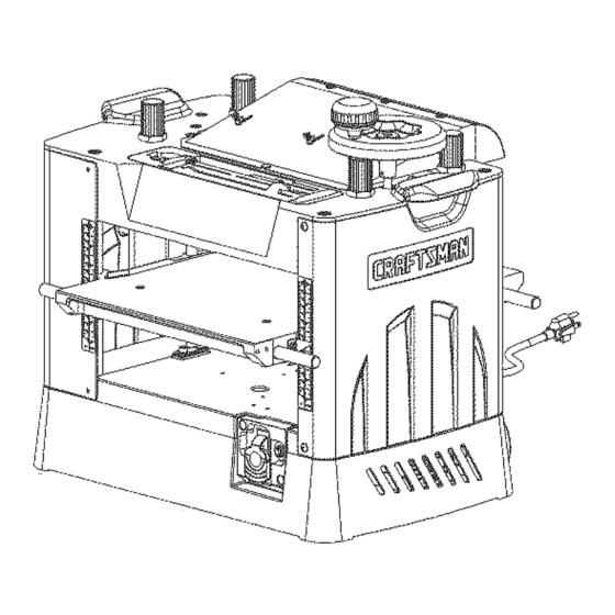
- Page 1 Operator's Manual CRRFT$14RN 13" PLANER/MOLDER Model No. 351.21 7330 CAUTION: Read and follow all Safety Rules and Operating Instructions before First Use of this Product. Sears, Roebuck and Co., Hoffman Estates, IL 60179 U.S.A. www.sears.com/craftsman 17509.02 Draft (08/31/01 )
- Page 2 PREPARE WORK AREA FOR JOB • Keep work area clean. Cluttered work areas invite Warranty ........accidents. Safety Rules....... • Do not use power tools in dangerous environments. Unpacking ........Do not use power tools in damp or wet locations. Do Assembly .........
- Page 3 See Recommended Accessories, page 21. MOUNTING INSTRUCTIONS FOR OPTIONAL TOOL STAND 222240 The Craftsman Planer/Molder Model 217330 can be " _ mounted directly on to Craftsman Multi-purpose Tool Stand Model 222240. To mount Planer/Molder to stand: •...
- Page 4 Properly Grounded Outlet Grounding Prong 3-Prong Figure 4 - 3-Prong Receptacle • Do not remove or alter grounding prong in any man- ner. In the event of a malfunction or breakdown, grounding provides a path of least resistance for electrical shock. WARNING: Do not permit fingers to touch the termi- nals of plug when installing or removing from outlet.
- Page 5 • Many cover plate screws, water pipes and outlet If the breaker is tripped, turn the planer/molder "off" and boxes are not properly grounded. To ensure proper reset the circuit by pressing the button. ground, grounding means must be tested by a quali- fied electrician.
- Page 6 • Maintain theproper relationships ofinfeed andout- Make a test cut on a piece of wood and measure the feedtablesurfaces andcutterhead b ladepath. thickness produced. • Donotbacktheworktoward theinfeed table. _,.-Up Down_ • Take precautions against k ickback. Donotpermit anyone to standor crossin lineofcutterhead's rota- tion.Kickback o r thrown debris willtravel i n this direction.
- Page 7 • Do not grasp any portion of board which has not gone past out-feed roller. • Repeat this operation on all boards which need to be same thickness. AVOIDING SNIPE 10 FPM Surface that the planer/molder will produce will be 0 FPM smoother if shallower depth of cut is used.
- Page 8 Adjust both ends of all three blades in a similar man- ner until all of the blades are at the same height. Tighten the gibs slowly, moving from one cutterhead slot to the next, until all three blades and all gibs are tight and secure.
- Page 9 MOLDING Bolt Bit Setting Gauge Molding, also known as millwork or trim, can be defined as a strip of wood milled with a plain or decorative sur- Spacers face which is continuous throughout its length. • To get superior molding finish, workpiece must be planed and presized prior to molding.
- Page 10 • Mount t hegibin onecutterhead s lotandtighten the • Use the bit setting gauge to align knives. setscrews onlyenough to holdthegibin position, • Be sure all knives and gibs are aligned, tight and thenmount t heothertwogibsin thesamemanner. secure. • Tighten thesetscrews on onegibslightly, thentight- The planer/molder cutterhead will accept multiple pat- entheothertwogibswithequal p ressure ontheset tern knife set-ups at one time.
- Page 11 a very smooth, level finish across the top is required. Fiber Hex Nut (De Not Adjust) Three sets of two blocks each are required, with height H=3", 211/,6 '' and 213/,6 ''. FEED ROLLER ADJUSTMENT Refer to Figures 20, 21, and 28, pages 11 and 18. The planer/molder feed rollers can be raised or lowered as needed.
- Page 12 GUIDE FENCES SETTING UP FOR MOLDING When molding, the workpiece must be guided into the • Mount auxiliary table onto cast iron table. molding cutter bits or knives properly in order to pro- • Install the required molding cutter bits/knives in the duce the desired shape and size molding.
- Page 13 EDGE MOLDING Refer to Figure 24 below. The workpiece edges can be molded by feeding the workpiece on edge into the planer/molder. Guide fences that are %" shorter than the workpiece must be positioned on the sides of the workpiece. Be sure the workpiece is supported rigidly on both sides by the guide fences directly under the cutter bits or knives.
- Page 14 ADJUSTING TABLE POSITION Refer to Figures 19 and 29, pages 10 and 20. The table is positioned parallel to the cutterhead at the factory and should need no further adjustment. If the planer is cutting one side of the workpiece deeper than the other producing a tapered cut, then the table may need to be adjusted.
- Page 15 SYMPTOM CORRECTIVE ACTION POSSIBLE CAUSE(S) 1. Dull blades Excessive snipe 1. Replace blades per instructions, see (gouging at ends of board) "Operation" 2. Inadequate support of long boards 2. Support long boards 3. Uneven feed roller pressure 3. Check feed roller operation 4.
- Page 16 Model 351.217330 <.\ Figure 27 - Replacement Parts Illustration for Gearbox and Table...
- Page 17 PART NO. DESCRIPTION QTY. 17110.00 Left Cover 17221.00 5-0.8 x lOmm Pan Head Screw 07365.00 Lifting Bar 06821.00 3CM1-12 Retaining Ring 03812.00 6-1.0 x lOmm Pan Head Screw 17112.00 Guide Plate 17113.00 Table 17114.00 Indicator 17115.00 Right Cover 17116.00 Gearbox STD315225 6202zz Bearing* 07370.00...
- Page 18 Model 351.217330 40 41 Figure 28 - Replacement Parts Illustration for Rollercase...
- Page 19 PART NO. DESCRIPTION QTY. 17087,00 Tool Tray 08581,00 Blade Height Gauge 08760,01 Wrench 09575,00 Brass Punch 16114,00 Wrench 17088,00 Bit Setting Gauge 17089.00 Chip Deflector Plate 17090.00 Blade Cover 03855,00 5-0,8 x 10ram Socket Head Bolt 03888,00 4mm Flat Washer 08566,00 Handwheel 17091.00...
- Page 20 Model 351.21 7330 _/12 Figure 29 - Replacement Parts Illustration for Base...
- Page 21 PART NO. DESCRIPTION QTY. PART NO. DESCRIPTION QTY. 16080.00 Switch 01505.00 6-1.0 x 12mm Socket Head Bolt 04287.00 Circuit Breaker STD852006 6mm Lock Washer* 00997.01 8mm Flat Washer 09656.00 Set Plate 17070.00 Switch Plate 16136.00 Cord Wrap STD851005 5mm Flat Washer* 02817.00 4 x 20mm Spring Pin 01474.00...
- Page 22 Model 351.217330 Figure 30 - Replacement Parts Illustration for Motor PART NO. DESCRIPTION QTY. 17081.00 Motor Assembly (Key Nos. 2-25) 17211.00 Hinge Shaft 17210.00 Motor Bracket 17214.00 Grommet 00361.00 5-0.8 x 8mm Pan Head Screw 01474.00 5mm Serrated Washer 01775.00 6-1.0 x 25mm Socket Head Bolt 17216.00 #14-10 x s/4"Thread Forming Screw...
- Page 23 NOTES...
- Page 24 CE PI L LADO RA/M OL D URADORA • Use una cubierta protectora para el cabello, para sujetar el cabello largo. DE 13" • Use zapatos de seguridad con suelas antideslizantes. • Use gafas de seguridad que cumplan con la norma ANSI Modelo No.
- Page 25 • Evite que la herramienta se encienda por accidente. Cerci6rese de que el interruptor este en la posici6n OFF (apagado) antes de enchufar la herramienta. • No fuerce la herramienta. Funcionara en la forma mas eft- ciente a la velocidad para la cual se diseff6.
- Page 26 PLATAFORMA OPCIONAL HERRAMIENTA 222240 INSTRUCCIONES PARA LA CONEXION A TIERRA La Cepilladora/Molduradora Craftsman Modelo 217330 puede ADVERTENCIA: Si no se conecta correctamente el conductor montarse directamente en una Plataforma para Herramienta Multi- a tierra del equipo, se corre el riesgo de un electrochoque.
- Page 27 Se puede usar temporalmente un adaptador de 3 puntas a 2 El motor se ensambla con un cable de tres conductores, aproba- puntas con conexi6n a tierra (v@ase la Figura 5) para conectar do para usarse con 110 voltios como se indica. La fuente de ali- los enchufes a un tomacorriente bipolar que est@ correctamente...
- Page 28 • AsegOrese que nada obstaculice ninguna parte movible. AJUSTANDO LA PROFUNDIDAD CORTE • Siempre use protecci6n para los ojos o para la cara. Consulte la Figura 7. • AsegQrese que las cuchillas esten alineadas y correctamente El grosor de la tabla que producirb, la cepilladora/molduradora acopladas al portacuchilla.
- Page 29 AVISO: Cambie la velocidad de alimentaci6n s61o mientras • No empuje ni tire de la pieza de trabajo. maquina este funcionando. • Muevase a la parte posterior y reciba la tabla cepillada • La velocidad de alimentaci6n se puede ajustar en tres posi- agarrdindola de la misma manera en que la hizo avanzar.
- Page 30 Ajuste los dos extremes de las tres cuchillas de manera similar hasta que todas las cuchillas queden a la misma altura. Apriete las cuBas de manera lenta, moviendose de una ranura del portacuchilla a la otra, hasta que las tres cuchillas y todas las cuhas queden apretadas...
- Page 31 MOLDEADO Perno Calibrador de ajuste de barrenas El moldeado, conocido tambien como carpinterfa prefabricada desbastado, puede definirse como una tira de madera fresada con Espaciadores un cepillo o superficie decorativa que es continua a traves de su Iongitud. • Para obtener un acabado de moldeado 6ptimo, la pieza de tra- bajo debe cepillarse...
- Page 32 • Siempre apriete las cu_as gradualmente y apriete las tres • Use el calibrador de ajuste de barrenas para alinear los cuchillos. cu_as en la ranura del portacuchilla a la misma vez. • Monte la cuba en una ranura del portacuchilla y apriete •...
- Page 33 Haga los bloques de madera de desecho dura con las dimen- Tuerca hexagonal de fibra (no la ajuste) siones que se muestran. Las medidas exactas no son cruciales pero se requiere un acabado nivelado y uniforme a traves de la parte superior.
- Page 34 PREPARACION PARA EL MOLDEADO REBORDES GUIA • Monte la mesa auxiliar sobre la mesa de hierro fundido. Cuando realice el moldeado, la pieza de trabajo deber& guiarse correctamente en las barrenas de cortadora de moldeado o los • Instale las barrenas de cortadoraicuchillos de moldeado nece-...
- Page 35 MOLDEADO DE BORDES Consulte la Figura 24 abajo. Los hordes de la pieza de trabajo pueden moldearse haciendo avanzar la pieza de trabajo en el borde en la cepilladora/ molduradora. Los rebordes gufa con una Iongitud de 3A" menor que la pieza de trabajo deben colocarse en los lados de la pieza de trabajo.
- Page 36 AJUSTE DE LA POSICION DE LA MESA Consulte las Figuras 19 y 29 en las p&ginas 32 y 20. La mesa viene colocada de fb.brica paralela al portacuchilla y no necesitarb, ning0n otro ajuste. Si la cepilladora corta un lade de la pieza de trabajo de forma m&s profunda que el otro, produciendo asi un corte ahusado,...
- Page 37 SINTOMA MEDIDA CORRECTIVA CAUSAS(S) POSIBLE(S) 1. Cuchillas desafiladas Redondeo excesivo 1. Reemplace las cuchillas segun las instrucciones, (depresiones en los vease "Operacion" extremes de la tabla) 2. Soporte inadecuado de las tablas 2. Soporte las tablas largas largas 3. Presi6n del rodillo de alimentacion 3.
- Page 38 NOTAS...
- Page 39 NOTAS...
- Page 40 Your Home For repair-in your home-of all major brand appliances, lawn and garden equipment, or heating and cooling systems, no matter who made it, no matter who sold it! For the replacement parts, accessories owner's manuals that you need to do-it-yourself. For Sears professional installation of home appliances...