Table of Contents
Advertisement
Advertisement
Table of Contents

Related Manuals for Asus P5KPL


Summary of Contents for Asus P5KPL
- Page 1 P5KPL...
- Page 2 Product warranty or service will not be extended if: (1) the product is repaired, modified or altered, unless such repair, modification of alteration is authorized in writing by ASUS; or (2) the serial number of the product is defaced or missing.
-
Page 3: Table Of Contents
Contents Notices ......................vi Safety information ..................vii P5KPL specifications summary ..............x Chapter 1: Product introduction Welcome! ..................1-2 Package contents ................. 1-2 Special features ................1-2 1.3.1 Product highlights ............1-2 1.3.2 ASUS Special features ........... 1-4 1.3.3 ASUS Overclocking features .......... - Page 4 Chapter 2: BIOS setup Managing and updating your BIOS ..........2-2 2.1.1 Creating a bootable floppy disk ........2-2 2.1.2 ASUS EZ Flash 2 utility ........... 2-4 2.1.3 AFUDOS utility ..............2-5 2.1.4 ASUS CrashFree BIOS 3 utility ........2-7 2.1.5...
- Page 5 2.6.2 Boot Settings Configuration .......... 2-31 2.6.3 Security ................. 2-32 Tools menu ................. 2-34 ASUS EZ Flash 2 ............2-34 Exit menu ..................2-35 Chapter 3: Software support Installing an operating system ........... 3-2 Support CD information .............. 3-2 3.2.1 Running the support CD ..........
-
Page 6: Notices
Notices Federal Communications Commission Statement This device complies with Part 15 of the FCC Rules. Operation is subject to the following two conditions: • This device may not cause harmful interference, and • This device must accept any interference received including interference that may cause undesired operation. -
Page 7: Safety Information
Safety information Electrical safety • To prevent electrical shock hazard, disconnect the power cable from the electrical outlet before relocating the system. • When adding or removing devices to or from the system, ensure that the power cables for the devices are unplugged before the signal cables are connected. -
Page 8: About This Guide
Refer to the following sources for additional information and for product and software updates. ASUS websites The ASUS website provides updated information on ASUS hardware and software products. Refer to the ASUS contact information. Optional documentation Your product package may include optional documentation, such as warranty flyers, that may have been added by your dealer. -
Page 9: Conventions Used In This Guide
Conventions used in this guide To make sure that you perform certain tasks properly, take note of the following symbols used throughout this manual. DANGER/WARNING: Information to prevent injury to yourself when trying to complete a task. CAUTION: Information to prevent damage to the components when trying to complete a task. -
Page 10: P5Kpl Specifications Summary
® Intel Hyper-Threading Technology ready ® Supports next generation 45nm multi-core CPU Supports Enhanced Intel SpeedStep Technology (EIST) ® Refer to www.asus.com for Intel CPU support list Chipset Northbridge: Intel ® Southbridge: Intel ICH7 ® Front Side Bus 1333 / 1066 / 800 MHz... - Page 11 P5KPL specifications summary Internal connectors 2 x USB 2.0 connectors supports additional 4 USB 2.0 ports 1 x Floppy disk drive connector 1 x IDE connector for two devices 4 x Serial ATA connectors 1 x CPU fan connector 1 x Chassis fan connector...
-
Page 13: Chapter 1: Product Introduction
This chapter describes the motherboard features and the new technologies it supports. Product introduction... -
Page 14: Welcome
Green ASUS This motherboard and its packaging comply with the European Union’s Restriction on the use of Hazardous Substances (RoHS). This is in line with the ASUS vision of creating environment-friendly and recyclable products/packaging to safeguard consumers’ health while minimizing the impact on the environment. -
Page 15: High Definition Audio
See page 1-29 for details. High Definition Audio Enjoy high-end sound quality on your PC! The onboard 6-channel HD audio (High Definition Audio, previously codenamed Azalia) CODEC enables high-quality 192KHz / 24-bit audio output, jack-detect feature. ASUS P5KPL... -
Page 16: Asus Special Features
BIOS easily without preparing a bootable diskette or using an OS-based flash utility. See page 2-4 for details. ASUS CrashFree BIOS 3 The ASUS CrashFree BIOS 3 allows users to restore corrupted BIOS data from a USB flash disk containing the BIOS file. See page 2-7 for details. 1.3.3 ASUS Overclocking features C.P.R. -
Page 17: Before You Proceed
ON, in sleep mode, or in soft-off mode. This is a reminder that you should shut down the system and unplug the power cable before removing or plugging in any motherboard component. The illustration below shows the location of the onboard LED. SB_PWR Standby Powered Power P5KPL Onboard LED ASUS P5KPL... -
Page 18: Motherboard Overview
Motherboard overview Before you install the motherboard, study the configuration of your chassis to ensure that the motherboard fits into it. Make sure to unplug the power cord before installing or removing the motherboard. Failure to do so can cause you physical injury and damage motherboard components. -
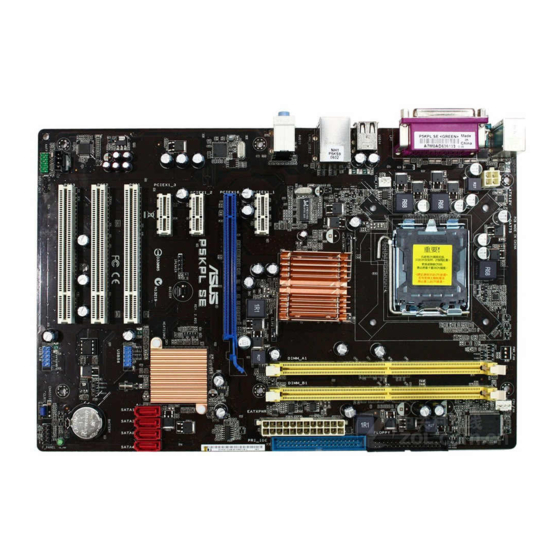
Page 19: Motherboard Layout
SATA2 SATA4 ICH7(A1) PCI3 ALC662 CR2032 3V BIOS USBPW5-8 Lithium Cell SATA1 SATA3 PCIEX1 CMOS Power AAFP CLRTC SB_PWR PRI_IDE FLOPPY USB56 USB78 Refer to section 1.10 Connectors for more information about rear panel connectors and internal connectors. ASUS P5KPL... -
Page 20: Layout Contents
1.5.4 Layout contents Slots Page DDR2 DIMM slots 1-16 PCI slots 1-24 PCI Express x1 slot 1-24 PCI Express x16 slot 1-24 Jumpers Page 1. Clear RTC RAM (3-pin CLRTC) 1-25 USB device wake-up (3-pin USBPW1-4, USBPW5-8) 1-26 Keyboard power (3-pin KBPWR) 1-26 Rear panel connectors Page... -
Page 21: Central Processing Unit (Cpu)
ASUS will shoulder the cost of repair only if the damage is shipment/transit-related. • Keep the cap after installing the motherboard. ASUS will process Return Merchandise Authorization (RMA) requests only if the motherboard comes with the cap on the LGA775 socket. -
Page 22: Installing The Cpu
Installing the CPU To install a CPU: Locate the CPU socket on the motherboard. P5KPL CPU Socket 775 Before installing the CPU, make sure that the cam box is facing towards you and the load lever is on your left. - Page 23 If installing a dual-core CPU, connect the chassis fan cable to the chassis fan connector to ensure system stability. ® The motherboard supports Intel LGA775 processors with Hyper-Threading Technology. Refer to the Appendix for more information on these CPU features. ASUS P5KPL 1-11...
-
Page 24: Installing The Cpu Heatsink And Fan
1.6.2 Installing the CPU heatsink and fan ® The Intel LGA775 processor requires a specially designed heatsink and fan assembly to ensure optimum thermal condition and performance. ® • When you buy a boxed Intel processor, the package includes the CPU fan and heatsink assembly. - Page 25 Connect the CPU fan cable to the connector on the motherboard labeled CPU_FAN. CPU_FAN P5KPL CPU Fan Connector Do not forget to connect the CPU fan connector! Hardware monitoring errors can occur if you fail to plug this connector. ASUS P5KPL...
-
Page 26: Uninstalling The Cpu Heatsink And Fan
1.6.3 Uninstalling the CPU heatsink and fan To uninstall the CPU heatsink and fan: Disconnect the CPU fan cable from the connector on the motherboard. Rotate each fastener counterclockwise. Pull up two fasteners at a time in a diagonal sequence to disengage the heatsink and fan assembly from the motherboard. - Page 27 The narrow end of the groove should point outward after resetting. (The photo shows the groove shaded for emphasis.) Refer to the documentation in the boxed or stand-alone CPU fan package for detailed information on CPU fan installation. ASUS P5KPL 1-15...
-
Page 28: System Memory
240-pin footprint compared to the 184-pin DDR DIMM. DDR2 DIMMs are notched differently to prevent installation on a DDR DIMM socket. The figure illustrates the location of the DDR2 DIMM sockets: P5KPL 240-pin DDR2 DIMM Sockets Channel Sockets Channel A... -
Page 29: Memory Configurations
Vista x64 Edition ® ® ® • Some old-version DDR2-800 DIMMs may not match Intel On-Die-Termination (ODT) requirement and will automatically downgrade to run at DDR-667. If this heppens, contact your memory vendor to check to ODT value. ASUS P5KPL 1-17... - Page 30 Qualified Vendors Lists (QVL) DDR2 667 DIMM support Size Vendor Model CL Brand Side(s) Component 256MB Kingston KVR667D2N5/256 N/A Kingston D3216TLSAKL3U • • • 256MB Kingston KVR667D2N5/256 N/A Infineon HYB18T256800AF3SW65 33154 • • • 512MB Kingston KVR667D2N5/512 N/A Kingston D6408TE8WL-27 •...
- Page 31 • • • HYMP512U64AP8-S6 AA N/A Hynix DS HY5PS12821AFP-S6 • • HYMP512U64BP8-S5 AB 5 Hynix DS HY5PS12821BFP-S5 • • HYMP512U64CP8-S5 AB 5 Hynix DS HY5PS12821CFPS5 • • 512MB ADATA M20AD6G3H3160I1E58 N/A ADATA SS AD29608A8A-25EG80720 • • • ASUS P5KPL 1-19...
- Page 32 N/A Veritech DS VTD264M8PC4G03A169045648 • • Visit the ASUS website (www.asus.com) for the latest QVL. Side(s): SS - Single-sided DS - Double-sided DIMM support: Supports one module inserted into any slot as Single-channel memory configuration. Supports one pair of modules inserted into either the yellow slots or the black slots as one pair of Dual-channel memory configuration.
-
Page 33: Installing A Dimm
DIMM. Support the DIMM lightly with your fingers when pressing the retaining clips. The DIMM might get damaged when it flips out with DDR2 DIMM notch extra force. Remove the DIMM from the socket. ASUS P5KPL 1-21... -
Page 34: Expansion Slots
Expansion slots In the future, you may need to install expansion cards. The following sub-sections describe the slots and the expansion cards that they support. Make sure to unplug the power cord before adding or removing expansion cards. Failure to do so may cause you physical injury and damage motherboard components. -
Page 35: Interrupt Assignments
— — — — Onboard USB 2.0 controller — — — — — — — shared Onboard HD audio shared — — — — — — — Onboard LAN — Used — — — — — — ASUS P5KPL 1-23... -
Page 36: Pci Slots
1.8.4 PCI slots The PCI slots support cards such as a LAN card, SCSI card, USB card, and other cards that comply with PCI specifications. The figure shows a LAN card installed on a PCI slot. 1.8.5 PCI Express x1 slot This motherboard supports PCI Express x1 network cards, SCSI cards and other cards that comply with the PCI Express... -
Page 37: Jumpers
CLRTC Normal Clear RTC (Default) P5KPL Clear RTC RAM • You do not need to clear the RTC when the system hangs due to overclocking. For system failure due to overclocking, use the C.P.R. (CPU Parameter Recall) feature. Shut down and reboot the system so the BIOS can automatically reset parameter settings to default values. -
Page 38: Keyboard Power (3-Pin Kbpwr)
(no power to CPU, DRAM in slow refresh, power supply in reduced power mode). USBPW1-4 USBPW5-8 P5KPL USB Device Wake Up • The USB device wake-up feature requires a power supply that can provide 500mA on the +5VSB lead for each USB port; otherwise, the system would not power up. -
Page 39: 1.10 Connectors
Line Out port (lime). This port connects a headphone or a speaker. In 4-channel and 6-channel configuration, the function of this port becomes Front Speaker Out. Microphone port (pink). This port connects a microphone. ASUS P5KPL 1-27... - Page 40 Refer to the audio configuration table below for the function of the audio ports in 2, 4, or 6-channel configuration. Audio 2, 4, or 6-channel configuration Port Headset 4-speaker 6-speaker 2-speaker Light Blue Line In Surround Out Surround Out Lime green Line Out Front Speaker Out Front Speaker Out...
-
Page 41: Internal Connectors
This connector is for the S/PDIF audio module to allow digital sound output. Connect one end of the S/PDIF audio cable to this connector and the other end to the S/PDIF module. SPDIFOUT SPDIF_OUT P5KPL Digital Audio Connector The S/PDIF out module is purchased separately. ASUS P5KPL 1-29... -
Page 42: Ide Connectors
If any device jumper is set as “Cable-Select,” make sure all other device jumpers have the same setting. PRI_IDE PIN1 NOTE: Orient the red markings (usually zigzag) on the ID ribbon cable to PIN 1. P5KPL IDE Connector 1-30 Chapter 1: Product introduction... -
Page 43: Graphics Cards
RSATA_TXN1 RSATA_TXN3 RSATA_RXN1 RSATA_RXN3 RSATA_RXP1 RSATA_RXP3 P5KPL SATA Connectors right angle side Connect the right-angle side of SATA signal cable to SATA device. Or you may connect the right-angle side of SATA cable to the onboard SATA port to avoid mechanical conflict with huge graphics cards. - Page 44 These USB connectors comply with USB 2.0 specification that supports up to 480 Mbps connection speed. USB78 USB56 P5KPL USB 2.0 Connectors Never connect a 1394 cable to the USB connectors. Doing so will damage the motherboard! The USB module is purchased separately.
- Page 45 These are not jumpers! Do not place jumper caps on the fan connectors! CPU_FAN CHA_FAN +12V Rotation PWR_FAN +12V P5KPL Fan Connectors Rotation Only the CPU-FAN connector supports the ASUS Advanced Q-Fan feature. ASUS P5KPL 1-33...
-
Page 46: Chassis Intrusion Connector (4-1 Pin Chassis)
HD Audio or legacy AC’97 audio standard. AAFP HD-audio-compliant Legacy AC 9 7 compliant definition pin definition P5KPL Front Panel Audio Connector • We recommend that you connect a high-definition front panel audio module to this connector to avail of the motherboard’s high-definition audio capability. •... - Page 47 +5 Volts +12 Volts Ground +3 Volts P5KPL ATX Power Connector • For a fully configured system, we recommend that you use a power supply unit (PSU) that complies with ATX 12 V Specification 2.0 (or later version) and provides a minimum power of 400 W.
-
Page 48: System Panel Connector
PLED+ IDE_LED+ Requires an ATX power supply System Panel Connector P5KPL • System power LED (2-pin PLED) This 2-pin connector is for the system power LED. Connect the chassis power LED cable to this connector. The system power LED lights up when you turn on the system power, and blinks when the system is in sleep mode. -
Page 49: Chapter 2: Bios Setup
This chapter tells how to change the system settings through the BIOS Setup menus. Detailed descriptions of the BIOS parameters are also provided. BIOS setup ASUS P5KPL... -
Page 50: Managing And Updating Your Bios
The following utilities allow you to manage and update the motherboard Basic Input/Output System (BIOS) setup. ASUS EZ Flash 2(Updates the BIOS in DOS mode using a floppy disk or USB flash disk.) ASUS AFUDOS (Updates the BIOS in DOS mode using a bootable floppy disk.) - Page 51 Right-click Floppy Disk Drive then click Format to display the Format 3 1/2 Floppy dialog box. d. Select the Create an MS-DOS startup disk check box. e. Click Start. Copy the original or the latest motherboard BIOS file to the bootable floppy disk. ASUS P5KPL...
-
Page 52: Asus Ez Flash 2 Utility
2.1.2 ASUS EZ Flash 2 utility The ASUS EZ Flash 2 feature allows you to update the BIOS without having to go through the long process of booting from a floppy disk and using a DOS-based utility. The EZ Flash 2 utility is built-in the BIOS chip so it is accessible by pressing <Alt>... -
Page 53: Afudos Utility
Extension name Press <Enter>. The utility copies the current BIOS file to the floppy disk. A:\>afudos /oOLDBIOS1.rom AMI Firmware Update Utility - Version 1.19(ASUS V2.07(03.11.24BB)) Copyright (C) 2002 American Megatrends, Inc. All rights reserved. Reading flash ..done Write to file..ok A:\>... -
Page 54: Updating The Bios File
Updating the BIOS file To update the BIOS file using the AFUDOS utility: Visit the ASUS website (www.asus.com) and download the latest BIOS file for the motherboard. Save the BIOS file to a bootable floppy disk. Write the BIOS filename on a piece of paper. You need to type the exact BIOS filename at the DOS prompt. -
Page 55: Asus Crashfree Bios 3 Utility
2.1.4 ASUS CrashFree BIOS 3 utility The ASUS CrashFree BIOS 3 is an auto recovery tool that allows you to restore the BIOS file when it fails or gets corrupted during the updating process. You can update a corrupted BIOS file using the motherboard support CD , the floppy disk or the USB flash disk that contains the updated BIOS file. -
Page 56: Recovering The Bios From The Support Cd
Restart the system after the utility completes the updating process. • Only the USB flash disk with FAT 32/16 format and single partition can support ASUS CrashFree BIOS 3. The device size should be smaller than 8GB. • DO NOT shut down or reset the system while updating the BIOS! Doing so... -
Page 57: Asus Update Utility
2.1.5 ASUS Update utility The ASUS Update is a utility that allows you to manage, save, and update the motherboard BIOS in Windows environment. The ASUS Update utility allows you ® • Save the current BIOS file • Download the latest BIOS file from the Internet •... - Page 58 To update the BIOS through the Internet: Launch the ASUS Update utility from the Windows desktop by clicking Start ® > Programs > ASUS > ASUSUpdate > ASUSUpdate. The ASUS Update main window appears. Select Update BIOS from Select the ASUS FTP site nearest...
- Page 59 To update the BIOS through a BIOS file: Launch the ASUS Update utility from the Windows desktop by clicking Start ® > Programs > ASUS > ASUSUpdate > ASUSUpdate. The ASUS Update main window appears. Select Update BIOS from a file option from the drop-down menu, then click Next.
-
Page 60: Bios Setup Program
The BIOS setup screens shown in this section are for reference purposes only, and may not exactly match what you see on your screen. • Visit the ASUS website (www.asus.com) to download the latest BIOS file for this motherboard. 2-12... -
Page 61: Bios Menu Screen
At the bottom right corner of a menu screen are the navigation keys for that particular menu. Use the navigation keys to select items in the menu and change the settings. Some of the navigation keys differ from one screen to another. ASUS P5KPL 2-13... -
Page 62: Menu Items
2.2.4 Menu items The highlighted item on the menu bar displays the specific items for that menu. System Time [11:10:19] Use [ENTER], [TAB] System Date [Thu 03/27/2003] or [SHIFT-TAB] to Legacy Diskette A [1.44M, 3.5 in] select a field. Legacy Diskette B [Disabled] For example, selecting Main shows the Main Use [+] or [-] to... -
Page 63: Main Menu
Allows you to set the system date. 2.3.3 Legacy Diskette A [1.44M, 3.5 in.] Sets the type of floppy drive installed. Configuration options: [Disabled] [360K, 5.25 in.] [1.2M, 5.25 in.] [720K, 3.5 in.] [1.44M, 3.5 in.] [2.88M, 3.5 in.] ASUS P5KPL 2-15... -
Page 64: Primary, Third And Fourth Ide Master/Slave
2.3.4 Primary, Third and Fourth IDE Master/Slave While entering Setup, the BIOS automatically detects the presence of IDE devices. There is a separate sub-menu for each IDE device. Select a device item then press <Enter> to display the IDE device information. BIOS SETUP UTILITY Main Advanced... -
Page 65: Ide Configuration
IDE Detect Time Out (Sec) [35] Enhanced ATA/IDE Configuration [Enhanced] Configuration options: [Disabled] [Compatible] [Enhanced] IDE Detect Time Out [35] Selects the time out value for detecting ATA/ATAPI devices. Configuration options: [0] [5] [10] [15] [20] [25] [30] [35] ASUS P5KPL 2-17... -
Page 66: System Information
2.3.6 System Information This menu gives you an overview of the general system specifications. The BIOS automatically detects the items in this menu. AMIBIOS Version : 0123 Build Date : 07/17/07 Processor Type : Genuine Intel(R) CPU 2.80GHz Speed : 2800MHz Count System Memory Usable Size: 512MB... -
Page 67: Advanced Menu
Manual - allows you to individually set overclocking parameters. Auto - loads the optimal settings for the system. Overclock Profile - loads overclocking profiles with optimal parameters for stability when overclocking. The following item appears only when you set the AI Overclocking item to [Manual]. ASUS P5KPL 2-19... -
Page 68: Usb Configuration
CPU Frequency [XXX] Displays the frequency sent by the clock generator to the system bus and PCI bus. The value of this item is auto-detected by the BIOS. Use the <+> and <-> keys to adjust the CPU frequency. You can also type the desired CPU frequency using the numeric keypad. -
Page 69: Usb Mass Storage Device Configuration
Floppy and remaining as hard drive. Forced FDD option can be used to force a HDD formatted drive to boost as FDD drive to boot as FDD. Configuration options: [Auto] [Floppy] [Forced FDD] [Hard Disk] [CDROM] ASUS P5KPL 2-21... -
Page 70: Cpu Configuration
2.4.3 CPU Configuration The items in this menu show the CPU-related information that the BIOS automatically detects. Configure advanced CPU settings Options Options Module Version: 3C.0E Manufacturer: Intel Auto Brand String: Genuine Intel(R) CPU 2.80GHz MANUAL Frequency : 2.80GHz FSB Speed : 800MHz Cache L1 : 32 KB... -
Page 71: Chipset
The Chipset menu allows you to change the advanced chipset settings. Select an item then press <Enter> to display the sub-menu. Configure North Bridge Advanced Chipset Settings features. WARNING: Setting wrong values in below sections may cause system to malfunction. North Bridge Configuration South Bridge Configuration ASUS P5KPL 2-23... -
Page 72: North Bridge Configuration
North Bridge Configuration ENABLE: Allow North Bridge chipset Configuration remapping of overlapped PCI memory Memory Remap Feature [Enabled] above the total Configure DRAM Timing by SPD [Enabled] physical memory. Initiate Graphic Adapter [PEG/PCI] DISABLE: Do not allow remapping of memory Memory Remap Feature [Enabled] Allows you to enable or disable the remapping of overlapped PCI memory above the total physical memory. -
Page 73: Onboard Devices Configuration
Appears only when the Parallel Port Mode is set to [ECP]. This item allows you to set the Parallel Port ECP DMA. Configuration options: [DMA0] [DMA1] [DMA3] Parallel Port IRQ [IRQ7] Allows you to select parallel port IRQ. Configuration options: [IRQ5] [IRQ7] ASUS P5KPL 2-25... -
Page 74: Pci Pnp
2.4.6 PCI PnP The PCI PnP menu items allow you to change the advanced settings for PCI/PnP devices. The menu includes setting IRQ and DMA channel resources for either PCI/PnP or legacy ISA devices, and setting the memory size block for legacy ISA devices. -
Page 75: Power Menu
Allows you to enable or disable the Advanced Configuration and Power Interface (ACPI) support in the Application-Specific Integrated Circuit (ASIC). When set to Enabled, the ACPI APIC table pointer is included in the RSDT pointer list. Configuration options: [Disabled] [Enabled] ASUS P5KPL 2-27... -
Page 76: Apm Configuration
2.5.5 APM Configuration APM Configuration Go into On/Off, or Suspend when Power Button Mode [On/Off] Power button Restore on AC Power Loss [Power Off] is pressed. Resume On Ring [Disabled] Resume On By PCI Devices [Disabled] Resume On By PCIE Devices [Disabled] Resume On RTC Alarm [Disabled]... -
Page 77: Hardware Monitor
(RPM). If the fan is not connected to the motherboard, the field shows N/A. Select Ignored if you do not wish to display the detected speed. CPU Q-Fan Control [Disabled] Allows you to enable or disable the Q-Fan control. Configuration options: [Disabled] [Enabled] ASUS P5KPL 2-29... -
Page 78: Boot Menu
Chassis Fan Speed [xxxxRPM] or [N/A] or [Ignored] The onboard hardware monitor automatically detects and displays the chassis fan speed in rotations per minute (RPM). If the fan is not connected to the chassis, the specific field shows N/A. Select Ignored if you do not wish to display the detected speed. VCORE Voltage, 3.3V Voltage, 5V Voltage, 12V Voltage The onboard hardware monitor automatically detects the voltage output through the onboard voltage regulators. -
Page 79: Boot Settings Configuration
This allows you to enable or disable the full screen logo display feature. Configuration options: [Disabled] [Enabled] Set this item to [Enabled] to use the ASUS MyLogo2™ feature. Add On ROM Display Mode [Force BIOS] Sets the display mode for option ROM. Configuration options: [Force BIOS]... -
Page 80: Security
Hit ‘DEL’ Message Display [Enabled] When set to Enabled, the system displays the message “Press DEL to run Setup” during POST. Configuration options: [Disabled] [Enabled] Interrupt 19 Capture [Disabled] When set to [Enabled], this function allows the option ROMs to trap Interrupt 19. Configuration options: [Disabled] [Enabled] 2.6.3 Security... -
Page 81: Change User Password
Password Check [Setup] When set to [Setup], BIOS checks for user password when accessing the Setup utility. When set to [Always], BIOS checks for user password both when accessing Setup and booting the system. Configuration options: [Setup] [Always] ASUS P5KPL 2-33... -
Page 82: Tools Menu
Exit ASUS EZ Flash 2 Allows you to run ASUS EZ Flash 2. When you press <Enter>, a confirmation message appears. Use the left/right arrow key to select between [Yes] or [No], then press <Enter> to confirm your choice. See page 2-3, section 2.1.2 for details. -
Page 83: Exit Menu
Setup menus. When you select this option or if you press <F5>, a confirmation window appears. Select OK to load default values. Select Exit & Save Changes or make other changes before saving the values to the non-volatile RAM. ASUS P5KPL 2-35... - Page 84 2-36 Chapter 2: BIOS setup...
-
Page 85: Chapter 3: Software Support
This chapter describes the contents of the support CD that comes with the motherboard package. Software support ASUS P5KPL... -
Page 86: Installing An Operating System
The contents of the support CD are subject to change at any time without notice. Visit the ASUS website(www.asus.com) for updates. 3.2.1 Running the support CD Place the support CD to the optical drive. The CD automatically displays the Drivers menu if Autorun is enabled in your computer. -
Page 87: Drivers Menu
The drivers menu shows the available device drivers if the system detects installed devices. Install the necessary drivers to activate the devices. ASUS InstAll-Drivers Installation Wizard Installs the ASUS InstAll-Drivers Installation Wizard. Intel Chipset Inf Update Program Installs the Intel chipset Inf update program. -
Page 88: Utilities Menu
ASUS InstAll-Installation Wizard for Utilities Installs all of the utilities through the Installation Wizard. ASUS Update The ASUS Update utility allows you to update the motherboard BIOS in a Windows environment. This utility requires an Internet connection either through ®... -
Page 89: Asus Contact Information
3.2.4 ASUS Contact information Click the Contact tab to display the ASUS contact information. You can also find this information on the inside front cover of this user guide. ASUS P5KPL... - Page 90 Chapter 3: Software support...
-
Page 91: Cpu Features
The Appendix describes the CPU features and technologies that the motherboard supports. CPU features... -
Page 92: Appendix: Cpu Features
32-bit operating systems. • The motherboard comes with a BIOS file that supports EM64T. You can download the latest BIOS file from the ASUS website (www.asus.com/support/download/) if you need to update the BIOS file. See Chapter 2 for details. -
Page 93: Using The Eist
Click Apply, then click OK. 10. Close the Display Properties window. After you adjust the power scheme, the CPU internal frequency slightly decreases when the CPU loading is low. The screen displays and procedures may vary depending on the operating system. ASUS P5KPL... -
Page 94: Intel ® Hyper-Threading Technology
Intel Hyper-Threading Technology ® • The motherboard supports Intel Pentium 4 LGA775 processors with ® ® Hyper-Threading Technology. • Hyper-Threading Technology is supported under Windows XP/2003 Server ® and Linux 2.4.x (kernel) and later versions only. Under Linux, use the Hyper-Threading compiler to compile the code.