Sony RCP-D50 Operating Instructions Manual
Memory stick remote control panel
Hide thumbs
Also See for RCP-D50:
- Operating instructions manual (194 pages) ,
- Service manual (152 pages)

Related Manuals for Sony RCP-D50


Summary of Contents for Sony RCP-D50
-
Page 1: Remote Control
3-776-792-12(1) Remote Control Panel Operating Instructions Before operating the unit, please read this manual thoroughly and retain it for future reference. RCP-D50/D51 2004 by Sony Corporation... - Page 2 For the customers in Europe WARNING This product with the CE marking complies with the EMC To prevent fire or shock hazard, do not expose the unit to Directive (89/336/EEC) issued by the Commission of the rain or moisture. European Community. Compliance with this directive implies conformity to the To avoid electrical shock, do not open the cabinet.
-
Page 3: Table Of Contents
Table of Contents Overview ................4 Features ................4 Locations and Functions of Parts ........5 Operation Panel ..............5 Connector Panel ..............13 Mounting on a Console ..........14 Menu Configuration and Basic Menu Operations ..15 Basic Operating Procedure ..........15 Basic Configuration of Menu Display ...... -
Page 4: Overview
Overview The RCP-D50/D51 Remote Control Panel enables Confirmation of camera conditions and remote operation of the DXC-D50-series, DXC-D30/ operation status D35-series,or DXC-637-series Color Video Cameras. This unit’s LCD panel indicates camera conditions such as the optical filter position, value, and lens The RCP-D50 and RCP-D51 are completely identical extender setting. -
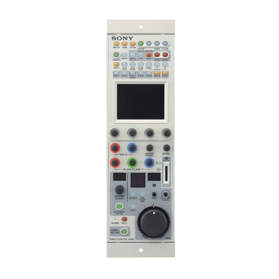
Page 5: Locations And Functions Of Parts
Locations and Functions of Parts Operation Panel 1 MASTER and SLAVE buttons qa ASSIGN button qs Power and output select buttons MASTER SLAVE ASSIGN CAM PW BARS CLOSE 2 PREVIEW button AUTO SETUP qd AUTO SETUP buttons 3 STANDARD button PREVIEW SKIN DTL LEVEL... - Page 6 Locations and Functions of Parts 1 MASTER and SLAVE buttons 5 WHITE (white balance manual adjustment) When adjusting the white balance of multiple cameras knobs in Master/Slave mode, designate the master camera or Used to manually adjust the white balance. the slave cameras.
- Page 7 0 PANEL ACTIVE button C CLOSE button Press and light up the button to permit this panel to Press and light the button to close the iris. To release control the camera system (Panel active status). the close mode, press the button again so that it goes The IRIS/M.BLACK ACTIVE button of the iris/ dark.
- Page 8 Locations and Functions of Parts qf White balance control buttons PRESET WHITE PRESET: Press and light this button to retrieve the preset white balance of the camera. A (memory A): Press and light this button to retrieve the white balance stored in memory A of the camera.
- Page 9 (When a CCU is used, the camera picture with characters is not displayed). If no camera picture is displayed with the CCU-TX7 connected, consult your Sony dealer. 3 LCD/touch panel Normally displays the statuses (see page 16)
- Page 10 Locations and Functions of Parts Iris/master black control block (RCP-D50) 3 IRIS/M.BLACK LINK button 4 IRIS/M.BLACK ACTIVE button 5 AUTO button 6 f-number display 7 EXT indicator IRIS/M.BLACK ACTIVE OPEN IRIS/M.BLACK 1 MASTER BLACK display LINK 8 SENS control knob MASTER SENS BLACK...
- Page 11 5 AUTO button qd IRIS RELATIVE (iris relative) button Press and light the button to automatically adjust the When the IRIS/M.BLACK ACTIVE button is lit, the iris according to the amount of input light. iris adjustment mode can be selected with this button. When this button is lit, the reference value for Press and light up the button for Relative mode or automatic iris adjustment can be set with the iris...
- Page 12 Locations and Functions of Parts Iris/master black control block (RCP-D51) 4 IRIS RELATIVE button 5 IRIS/M.BLACK LINK button 1 MASTER BLACK display 6 f-number display 7 EXT indicator 2 MASTER BLACK control 8 SENS control knob MASTER 9 COARSE control knob BLACK RELATIVE IRIS/...
-
Page 13: Connector Panel
8 SENS (sensitivity) control knob Connector Panel Used for manual iris adjustment in Absolute mode. This control is not operative when Relative mode is selected. 1 MONITOR connector See the table “Iris adjustment functions”on page 11. 2 CCU/CAMERA connector 9 COARSE control knob 3 EXT I/O connector Used for manual iris adjustment. -
Page 14: Mounting On A Console
Mounting on a Console The RCP-D50/D51 can be mounted on a console as shown below:... -
Page 15: Menu Configuration And Basic Menu Operations
Menu Configuration and Basic Menu Operations The RCP-D50/D51 provides menu operations for When the selected menu is composed of various functions such as adjustments of system multiple pages equipment. With the menu that is composed of multiple pages such as Paint menu, press v or V to flip the pages. See “Initial display (Paint menu)”... -
Page 16: Basic Configuration Of Menu Display
Menu Configuration and Basic Menu Operations Basic Configuration of Menu Display Status display When you do not select any menu or the signal from the camera, the LCD shows the following status display: On the status display, the set value of each item is only displayed. - Page 17 Adjustment display (Paint menu) When you select an item on the initial display of the Paint menu, the lower half of the panel becomes the adjustment display for the selected item. Example: when you select “White” from the PAINT 1 initial display with the DXC-D50 series connected The name of the item selected on the initial display is displayed.
- Page 18 Menu Configuration and Basic Menu Operations Function menu displays When you press and light the FUNCTION button of the menu operation block, the scene file operation menu display is obtained. When “Operation” is selected Example: with the DXC-D50 series connected The ND filter number being selected Filter Opera-...
- Page 19 Monitor output set display (Expansion menu) [Monitor Select] When you press on an adjustment display of the Paint menu, the upper half of the panel becomes the monitor output setting display. When the CCU-TX7 is connected, you can select the WF/PIX output signals. R/G/B: To independently select the R, Monitor Select G, or B signal.
-
Page 20: Menu Items With The Dxc-D50-Series Cameras
Menu Configuration and Basic Menu Operations Menu Items with the DXC-D50-Series Cameras The “Control items” marked with are those assigned The items displayed differ according to whether the to the control knobs. The other items are operated on unit is in Advanced Setting mode or in Normal Setting the menu display. - Page 21 Page Menu Submenu Control item Function Paint 2 Detail Detail 1 • Level To adjust the detail (contour correction) level • H/V Ratio To adjust the ratio of V (Vertical) detail to H (Horizontal) detail in detail correction. As the value becomes larger, the V detail ratio increases.
- Page 22 Menu Configuration and Basic Menu Operations Page Menu Submenu Control item Function Paint 4 White Clip • Master To adjust the amount of white clip (the highest white level). As the value becomes larger, the output level decreases. TLCS TLCS To turn the TLCS (total level control) function ON/OFF •...
- Page 23 Function menu (with the DXC-D50 series) Menu Control item Function Operation Jump menu 1 To jump to the adjustment screen designated for Menu 1 in Menu Set (Default: White of Paint 1) Jump menu 2 To jump to the adjustment screen designated for Menu 2 in Menu Set (Default:Black of Paint 1) Jump menu 3 To jump to the adjustment screen designated for Menu 3 in Menu Set...
- Page 24 Menu Configuration and Basic Menu Operations OTHERS menu (with the DXC-D50 series) Menu 2ndary menu Submenu Control item Function Adjusting White Shading • R To adjust the V white shading (vertical variation of the white) of the R signal • G To adjust the V white shading of the G signal •...
- Page 25 Menu 2ndary menu Submenu Control item Function RCP Config VR Setting M. Black VR (Only available for RCP-D50) To select the response rate of the (cont.) (cont.) MASTER BLACK knob (relative-value adjustment rates: 1/1, 1/2, and 1/4, where 1/1 is the quickest response position) Information To display the software version of the unit Cable Comp...
- Page 26 Menu Configuration and Basic Menu Operations Menu 2ndary menu Submenu Control item Function RCP Config Security Engineer Mode To set whether to display “Status”, “Menu Set”, and “Code No.” or (cont.) not (With Engineer Mode ON, all operative menu items are displayed regardless of the Advance Mode setting.) Status Advance Mode...
-
Page 27: Menu Items With The Dxc-D30/D35-Series Cameras
Menu Items with the DXC-D30/D35-Series Cameras The “Control items” marked with are those assigned The items displayed differ according to whether the to the control knobs. The other items are operated on unit is in Advanced Setting mode or in Normal Setting the menu display. - Page 28 Menu Configuration and Basic Menu Operations Page Menu Submenu Control item Function Paint 2 Detail Detail 1 • Level To adjust the detail (contour correction) level • H/V Ratio To adjust the ratio of V (vertical) detail to H (horizontal) detail in detail correction.
- Page 29 Page Menu Submenu Control item Function Paint 2 Black STR Black • Level To adjust the black stretch level (cont.) Stretch 1 • Stretch Level/Point 1 To adjust the upper limit of the signal levels that activate the black stretch function •...
- Page 30 Menu Configuration and Basic Menu Operations Page Menu Submenu Control item Function Paint 4 CLS/EVS TLCS To turn the TLCS (total level control) function ON/OFF (cont.) Shutter To turn the shutter function ON/OFF To turn the CLS (clear scan) function (which reduces noise on the horizontal scan lines when the monitor screen connected to a PC is shot) ON/OFF To turn the EVS mode (which reduces flicker by increasing the...
- Page 31 Menu Submenu Control item Function Lens/Pan Option 1 To turn the option control function 1 ON/OFF Option 2 To turn the option control function 2 ON/OFF • Focus To adjust the focus • Zoom To adjust the zoom • Pan To adjust panning of the tripod head •...
- Page 32 Menu Configuration and Basic Menu Operations Menu 2ndary menu Submenu Control item Function RCP Config RCP LED Bright • Switch To set the brightness of respective LEDs (cont.) Adjusting • Tally (cont.) • Other • Master To set the brightness of the all LEDs of the unit RE Setting BLACK/FLARE To select the function for the BLACK/FLARE knob...
- Page 33 Menu 2ndary menu Submenu Control item Function RCP Config Security Engineer Mode To set whether to display “Status”, “Menu Set”, and “Code No.” or (cont.) not (With Engineer Mode ON, all operative menu items are displayed regardless of the Advance Mode setting.) Status Advance Mode To switch between the Normal Setting mode and Advanced Setting...
-
Page 34: Menu Items With The Dxc-637-Series Cameras
Menu Configuration and Basic Menu Operations Menu Items with the DXC-637-Series Cameras The “Control items” marked with are those assigned The items displayed differ according to whether the to the control knobs. The other items are operated on unit is in Advanced Setting mode or in Normal Setting the menu display. - Page 35 Function menu (with the DXC-637 series) Menu Control item Function Operation Jump menu 1 To jump to the adjustment screen designated for Menu 1 in Menu Set (Default: White of Paint 1) Jump menu 2 To jump to the adjustment screen designated for Menu 2 in Menu Set (Default:Black of Paint 1) Jump menu 3 To jump to the adjustment screen designated for Menu 3 in Menu Set...
- Page 36 Menu Configuration and Basic Menu Operations OTHERS menu (with the DXC-637 series) Menu 2ndary menu Submenu Control item Function Camera Title ID Title IND To turn the title display ON/OFF while the camera is in Color Bars Config mode Clock IND Switching of the clock indication Cam: To always display the clock indication Off: No clock indication...
- Page 37 Menu 2ndary menu Submenu Control item Function RCP Config Comm Link Gain To turn ON/OFF command link operation (activation of several (cont.) cameras at the same time) of the gain Shutter To turn ON/OFF command link operation of shutter settings R/B White To turn ON/OFF command link operation of the white R/B adjustment...
-
Page 38: Menu Items With The Ccu-Tx50
Menu Configuration and Basic Menu Operations Menu Items with the CCU-TX50 The “Control items” marked with are those assigned The items displayed differ according to whether the to the control knobs. The other items are operated on unit is in Advanced Setting mode or in Normal Setting the menu display. - Page 39 Page Menu Submenu Control item Function Paint 2 Detail Detail 1 • Level To adjust the detail (contour correction) level • H/V Ratio To adjust the ratio of V (Vertical) detail to H (Horizontal) detail in detail correction. As the value becomes larger, the V detail ratio increases.
- Page 40 Menu Configuration and Basic Menu Operations Page Menu Submenu Control item Function Paint 4 White Clip • Master To adjust the amount of white clip (the highest white level). As the value becomes larger, the output level decreases. TLCS TLCS To turn the TLCS (total level control) function ON/OFF •...
- Page 41 To control the lens from this unit, the optional focus zoom servo unit and the interface unit for the camera adapter and lens are required. In addition, special settings must be made on the connected CA-TX50. For details, consult your Sony dealer.
- Page 42 Menu Configuration and Basic Menu Operations OTHERS menu (with the CCU-TX50) Menu 2ndary menu Submenu Control item Function Adjusting White Shading • R To adjust the V white shading (vertical variation of the white) of the R signal • G To adjust the V white shading of the G signal •...
- Page 43 Menu 2ndary menu Submenu Control item Function RCP Config Date/Time Date • Year Date adjustment of the clock built into the unit (cont.) • Month • Day Cancel Time • Hour Time adjustment of the clock built into the unit •...
- Page 44 Menu Configuration and Basic Menu Operations Menu 2ndary menu Submenu Control item Function LCD Brightness/Contrast • Bright To set the brightness of the LCD of the unit (cont.) • Cont To set the contrast of the LCD of the unit LCD Moni.
-
Page 45: Initial Settings
Initial Settings Setting the Operating Conditions RCP Config. Menu Exit of the RCP-D50/D51 Adjusting Setting By using the RCP Config menu or LCD setting display, you can set the built-in clock of the RCP-D50/ Cable Camera Date Comp Setting Time D51 and adjust various conditions of the RCP-D50/ D51, such as the sound volume of the warning buzzer Secu-... -
Page 46: Adjusting The Buzzer Sound
Initial Settings To set the date: Adjusting the Buzzer Sound [Date] 1) Press and light A buzzer sounds on the RCP-D50/D51 when it receives call signal or a panel control is operated. Date Time Setting Exit When required, you may turn on/off the buzzer or adjust the sound volume. -
Page 47: Adjusting The Brightness Of The Leds
To turn on/off the buzzers independently lamps, including the master black indicator and Press the corresponding button. When it is lit, the f-number indicator buzzer is on. The master brightness can be adjusted with the [Call Buzzer] : For the buzzer sound when a call signal rightmost control knob (Master). -
Page 48: Adjusting The Brightness/Contrast Of The Lcd
Initial Settings Set the menu to Advanced Setting mode. Adjusting the Brightness/ 1) Press [Security] on the RCP Config menu. Contrast of the LCD 2) Press and highlight [Engineer Mode]. You can adjust the brightness and contrast of the The [Status], [Menu Set], and [Code No.] buttons display of the menu control block. -
Page 49: Specifying The Security Codes
If you enter an incorrect security code, the message Specifying the Security Codes “!!!Code No. NG!!!” is displayed. You can authorize specific persons to set the menu to When you enter the correct security code, the Engineer mode, to operate this panel, and to adjust the Security Code setting display is resumed with iris and master black by specifying a security code. - Page 50 Initial Settings The Security Code input display appears. Press B to display the second page and press [Enable $ENG Code%] [Disable] (Pressing registers the same security code as Engineer mode for Panel Active Lock.) The security code is disabled. Operate in the same manner as step 5 and step 6 in Changing a security code “Locking Engineer mode with a security code.”...
-
Page 51: File Operations
File Operations This unit can operate two types of files: scene files and The table below shows the setting items which can be setup files. registered as either of the files. Setting data of cameras can be registered as scene files or setup files and recalled as required. - Page 52 File Operations Setup file Scene file Setting item DXC-D30/D35 DXC-D30/D35 DXC-D50 DXC-637 series only series series series Gamma correction on/off Master gamma R/B gamma Master black gamma R/B black gamma Gamma initial gain Black stretch level Upper/lower limit value for black stretch Upper/lower limit value for black compress DynaLatitude effect Matrix adjustment ON/OFF...
-
Page 53: Operating Scene Files
If the scene file button corresponding to the Operating Scene Files memory cell in which you wish to store data is not displayed, press either the v or V button at the Scene files are stored in the memory of this unit (or of lower-right position. -
Page 54: Transferring Scene Files Between The Camera And A Memory Stick (With The Dxc-D50 Series)
File Operations Reading the scene files from a Memory Transferring Scene Files between Stick the Camera and a Memory Stick (with the DXC-D50 Series) Proceed as follows: Insert the Memory Stick ( see page 59 When a DXC-D50-series camera is connected, the registered scene files can be stored as a data block and Operate in the same manner as when you stored can be read when required. -
Page 55: Operating Setup Files (For Dxc-D30/D35 Series Only)
Press [Store]. Operating Setup Files (for DXC- D30/D35 Series only) The current settings of the camera are stored as a setup file with the name entered in Step 4, and that Among the setting items listed in the table on pages 51 filename is displayed on the list. -
Page 56: Skin Detail Correction/Skin Matrix Adjustment (For Dxc-D30/D35/D50 Series Only)
Skin Detail Correction/Skin Matrix Adjustment (for DXC-D30/D35/D50 Series Only) The skin detail and skin matrix functions can adjust If you power off the unit or store the current detail level and matrix (saturation and hue) of a settings as a scene file while setting the detail level selected skin gate area (area designated by color to the minimum value, the skin detail function will range). -
Page 57: Multi-Camera Control
CCU to make a daisy chain of the CCUs. For more information about cables which can be used, On the cameras connected to the RCP units whose consult your Sony dealer. IRIS/M.BLACK LINK buttons light, the iris or master black adjustments are performed by the... -
Page 58: Operating Multiple Cameras From One Rcp Unit -Command Link
Multi-Camera Control • The command link adjustment of R/G/B flare Notes correction is available only with the DXC-D30/D35/ • While scene file transfer is in progress on a slave D50 series. unit, do not tranfer data from the master unit to the slave unit. -
Page 59: Memory Sticks
Memory Sticks Using a Memory Stick Notes on Memory Stick When a Memory Stick is inserted in the panel, the file On Memory Stick data can be stored on the Memory Stick, which enables you to share data among RCPs. Memory Stick is a new compact, portable and versatile IC recording medium with a data capacity that exceeds that of a floppy disk. - Page 60 Memory Stick, be sure to use Memory Sticks of a size that can be used with both the RCP-D50/D51 and the camera. Memory Stick and are the trademarks of Sony Corporation. MagicGate Memory Stick and are the trademarks of Sony Corporation.
-
Page 61: Specifications
Specifications General Power requirements 10.5 to 17 V DC Power consumption 4.5 W Cable length 50 m (164 feet) max. (when the CCA-7 cable is used) Operating temperature 5°C to 40°C (41°F to 104°F) Dimensions (w/h/d) RCP-D50: 102 × 354 × 126.5 mm ×... - Page 62 Sony Corporation...