Table of Contents
Advertisement
Advertisement
Table of Contents

Related Manuals for Asus M4N68T-M LE V2


Summary of Contents for Asus M4N68T-M LE V2
- Page 1 M4N68T-M V2/ M4N68T-M LE V2...
- Page 2 Product warranty or service will not be extended if: (1) the product is repaired, modified or altered, unless such repair, modification of alteration is authorized in writing by ASUS; or (2) the serial number of the product is defaced or missing.
-
Page 3: Table Of Contents
Welcome! ..................1-1 Package contents ................. 1-1 Special features ................1-1 1.3.1 Product highlights ............1-1 1.3.2 Innovative ASUS features ..........1-3 Before you proceed ..............1-5 Motherboard overview ..............1-6 1.5.1 Placement direction ............1-6 1.5.2 Screw holes ..............1-6 1.5.3... - Page 4 Chapter 2: BIOS information Managing and updating your BIOS ..........2-1 2.1.1 ASUS Update utility ............2-1 2.1.2 ASUS EZ Flash 2 utility ........... 2-2 2.1.3 ASUS CrashFree BIOS utility ......... 2-3 BIOS setup program ..............2-4 2.2.1 BIOS menu screen ............2-5 2.2.3...
- Page 5 Boot Device Priority ............2-19 2.6.2 Boot Settings Configuration .......... 2-19 2.6.3 Security ................. 2-20 Tools menu ................. 2-22 2.7.1 ASUS EZ Flash 2 ............2-22 2.7.2 ASUS O.C. Profile ............2-22 2.7.3 AI NET 2................ 2-23 Exit menu ..................2-24...
-
Page 6: Notices
Complying with the REACH (Registration, Evaluation, Authorisation, and Restriction of Chemicals) regulatory framework, we published the chemical substances in our products at ASUS REACH website at http://csr.asus.com/english/REACH.htm. DO NOT throw the motherboard in municipal waste. This product has been designed to enable proper reuse of parts and recycling. -
Page 7: Safety Information
Safety information Electrical safety • To prevent electric shock hazard, disconnect the power cable from the electric outlet before relocating the system. • When adding or removing devices to or from the system, ensure that the power cables for the devices are unplugged before the signal cables are connected. If possible, disconnect all power cables from the existing system before you add a device. -
Page 8: Conventions Used In This Guide
Refer to the following sources for additional information and for product and software updates. ASUS websites The ASUS website provides updated information on ASUS hardware and software products. Refer to the ASUS contact information. Optional documentation Your product package may include optional documentation, such as warranty flyers, that may have been added by your dealer. -
Page 9: M4N68T-M Series Specifications Summary
2 x 240-pin DIMM slots support maximum 8GB unbuffered ECC and non-ECC DDR3 1800(O.C.) / 1600 (O.C.) / 1333 / 1066MHz memory modules * Refer to www.asus.com for the latest Memory QVL (Qualified Vendors List). ** When you install a total memory of 4GB or more,... - Page 10 SFS (Stepless Frequency Selection) - HT tuning from 200MHz to 300MHz at 1MHz increment - PCIe frequency tuning from 100MHz to 150MHz at 1MHz increment ASUS C.P.R. (CPU Parameter Recall) Accessories 2 x Serial ATA cables 1 x Ultra DMA 133/100 cable...
-
Page 11: Chapter 1: Product Introduction
Documentation User Manual • M4N68T-M Series motherboards include these two models: M4N68T-M V2 and M4N68T-M LE V2. The package contents vary with models. • If any of the above items is damaged or missing, contact your retailer. Special features 1.3.1 Product highlights Phenom™... - Page 12 Cool ‘n’ Quiet Technology ® This motherboard supports the AMD Cool ‘n’ Quiet technology which ® monitors system operation and automatically adjusts CPU voltage and frequency for a cool and quiet operating environment. Dual-Channel DDR3 1800 (O.C.) support This motherboard supports DDR3 memory that features data transfer rates of 1800 (O.C.)/1600 (O.C.)/1333/1066 MHz to meet the higher bandwidth requirements of the latest operating system, 3D graphics, multimedia, and Internet applications.
-
Page 13: Innovative Asus Features
BIOS file using the bundled support DVD or a USB flash disk that contains the BIOS file. ASUS EZ Flash 2 ASUS EZ Flash 2 allows you to update the BIOS from a USB flash disk before entering the OS. ASUS Q-Fan... - Page 14 ASUS AI NET2 ASUS AI NET2 remotely detects the cable connection immediately after you turn on the system and any faulty cable connections are reported back up to 100 meters at 1 meter accuracy. C.P.R. (CPU Parameter Recall) The BIOS C.P.R. feature automatically restores the CPU default settings when the system hangs due to overclocking failure.
-
Page 15: Before You Proceed
ON, in sleep mode, or in soft-off mode. This is a reminder that you should shut down the system and unplug the power cable before removing or plugging in any motherboard component. The illustration below shows the location of the onboard LED. SB_PWR M4N68T-M V2 Standby Power Powered Off M4N68T-M Series Onboard LED ASUS M4N68T-M Series... -
Page 16: Motherboard Overview
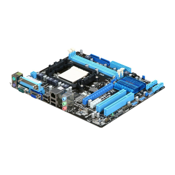
Motherboard overview 1.5.1 Placement direction When installing the motherboard, ensure that you place it into the chassis in the correct orientation. The edge with external ports goes to the rear part of the chassis as indicated in the image below. 1.5.2 Screw holes Place six screws into the holes indicated by circles to secure the motherboard to the chassis. -
Page 17: Motherboard Layout
CPU_FAN and 3-pin CHA_FAN) AMD CPU socket Onboard LED DDR3 DIMM sockets 1-11 Digital audio connector (4-1 pin SPDIF_OUT) 1-27 IDE connector (40-1 pin PRI_IDE) 1-23 Front panel audio connector (10-1 pin AAFP) 1-21 Clear RTC RAM (CLRTC) 1-18 ASUS M4N68T-M Series... -
Page 18: Central Processing Unit (Cpu)
Central Processing Unit (CPU) This motherboard supports AMD Phenom™ II / Athlon™ II / Sempron™ 100 series ® processors. The AM3 socket has a different pinout from the the AM2+/AM2 socket. Ensure that you use a CPU designed for the AM3 socket. 1.6.1 Installing the CPU To install a CPU:... - Page 19 CPU FAN PWM M4N68T-M V2 CPU FAN IN CPU FAN PWR M4N68T-M Series CPU fan connector DO NOT forget to connect the CPU fan connector! Hardware monitoring errors can occur if you fail to plug this connector. ASUS M4N68T-M Series...
-
Page 20: Installing The Heatsink And Fan
1.6.2 Installing the heatsink and fan Ensure that you use only AMD-certified heatsink and fan assembly. To install the CPU heatsink and fan: Place the heatsink on top of the installed CPU, ensuring that the heatsink fits properly on the retention module base. •... -
Page 21: System Memory
The motherboard comes with two Double Data Rate 3 (DDR3) Dual Inline Memory Modules (DIMM) sockets. The figure illustrates the location of the DDR3 DIMM sockets: Channel Sockets Channel A DIMM_A1 Channel B DIMM_B1 M4N68T-M V2 M4N68T-M Series 240-pin DDR3 DIMM sockets ASUS M4N68T-M Series 1-11... -
Page 22: Memory Configurations
1.7.2 Memory configurations You may install 512MB, 1GB, 2GB, and 4GB unbuffered ECC and non-ECC DDR3 DIMMs into the DIMM sockets. • You may install varying memory sizes in Channel A and Channel B. The system maps the total size of the lower-sized channel for the dual-channel configuration. Any excess memory from the higher-sized channel is then mapped for single-channel operation. -
Page 23: Ddr3-1333 Mhz Capability
4096MB(Kit of 2) Heat-Sink Package 6-6-6-20 1.8V • • Crucial BL25664BN1337.16FF 6144MB(Kit of 3 ) DS Heat-Sink Package 7-7-7-24 1.65V • • (XMP) Crucial CT25664BA1339.16SFD 6144MB(Kit of 3 ) DS Micron 8UD22D9JNM • (continued on the next page) ASUS M4N68T-M Series 1-13... - Page 24 DDR3-1333MHz capability DIMM Timing Support Vendor Part No. Size Brand Chip NO. DIMM Voltage (BIOS) G.SKILL F3-10600CL8D-2GBHK 1024MB G.SKILL Heat-Sink Package • G.SKILL F3-10600CL9D-2GBPK 1024MB G.SKILL Heat-Sink Package • • G.SKILL F3-10666CL7T-3GBPK 3072MB(Kit of 3) Heat-Sink Package 7-7-7-18 1.5~1.6V • •...
- Page 25 • A*: Supports one module inserted into either slot as single-channel memory configuration. • B*: Supports one pair of modules inserted into both the blue slots as one pair of dual-channel memory configuration. Visit the ASUS website at www.asus.com for the latest QVL. ASUS M4N68T-M Series 1-15...
-
Page 26: Installing A Dimm
1.7.3 Installing a DIMM Unplug the power supply before adding or removing DIMMs or other system components. Failure to do so can cause severe damage to both the motherboard and the components. Press the retaining clips outward to DIMM notch unlock a DIMM socket. -
Page 27: Expansion Slots
This motherboard supports PCI Express x1 network cards, SCSI cards, and other cards that comply with the PCI Express specifications. 1.8.5 PCI Express x16 slot This motherboard supports a PCI Express x16 graphics card that comply with the PCI Express specifications. ASUS M4N68T-M Series 1-17... -
Page 28: Jumpers
Jumpers Clear RTC RAM (CLRTC) This jumper allows you to clear the Real Time Clock (RTC) RAM in CMOS. You can clear the CMOS memory of date, time, and system setup parameters by erasing the CMOS RTC RAM data. The onboard button cell battery powers the RAM data in CMOS, which include system setup information such as system passwords. -
Page 29: Usb Device Wake-Up
(the default is the Space Bar). This feature requires an ATX power supply that can supply at least 1A on the +5VSB lead, and a corresponding setting in the BIOS. KBPWR +5VSB (Default) M4N68T-M V2 M4N68T-M Series Keyboard Power Setting ASUS M4N68T-M Series 1-19... -
Page 30: Connectors
1.10 Connectors 1.10.1 Rear panel ports PS/2 Mouse port (green). This port is for a PS/2 mouse. Parallel port. This 25-pin port connects a parallel printer, a scanner, or other devices. LAN (RJ-45) port. This port allows Gigabit connection to a Local Area Network (LAN) through a network hub. -
Page 31: Front Panel Audio Connector
• If you want to connect a high definition front panel audio module to this connector, set the Front Panel Select item in the BIOS to [HD Audio]. See section 2.4.3 Chipset for details. • The front panel audio I/O module is purchased separately. ASUS M4N68T-M Series 1-21... -
Page 32: Atx Power Connectors
The system may become unstable or may not boot up if the power is inadequate. • If you are uncertain about the minimum power supply requirement for your system, refer to the Recommended Power Supply Wattage Calculator at http://support.asus. com/PowerSupplyCalculator/PSCalculator.aspx?SLanguage=en-us for details. 1-22... - Page 33 If any device jumper is set as “Cable-Select”, ensure that all other device jumpers have the same setting. PRI_IDE M4N68T-M V2 PIN1 NOTE:Orient the red markings on the IDE ribbon cable to PIN 1. M4N68T-M Series IDE connector ASUS M4N68T-M Series 1-23...
-
Page 34: Serial Ata Connectors
Serial ATA connectors (7-pin SATA1, SATA2, SATA3, SATA4) These connectors are for the Serial ATA signal cables for Serial ATA 3Gb/s hard disk and optical disk drives. The Serial ATA 3Gb/s is backward compatible with Serial ATA 1.5Gb/s specification. The data transfer rate of the Serial ATA 3Gb/s is faster than the standard parallel ATA with 133MB/s (Ultra DMA133). -
Page 35: System Panel Connector
Power/Soft-off button (2-pin PWRBTN) This 2-pin connector is for the system power button. • Reset button (2-pin RESET) This 2-pin connector is for the chassis-mounted reset button for system reboot without turning off the system power. ASUS M4N68T-M Series 1-25... -
Page 36: Usb Connectors
USB connectors (10-1 pin USB56, USB78, USB910) These connectors are for USB 2.0 ports. Connect the USB module cable to any of these connectors, then install the module to a slot opening at the back of the system chassis. These USB connectors comply with USB 2.0 specification that supports up to 480Mbps connection speed. - Page 37 DO NOT forget to connect the fan cables to the fan connectors. Insufficient air flow inside the system may damage the motherboard components. These are not jumpers! DO NOT place jumper caps on the fan connectors. Only the 4-pin CPU fan connector supports the ASUS Q-Fan feature. ASUS M4N68T-M Series 1-27...
-
Page 38: Software Support
The contents of the Support DVD are subject to change at any time without notice. Visit the ASUS website at www.asus.com for updates. To run the Support DVD Place the Support DVD into the optical drive. -
Page 39: Chapter 2: Bios Information
BIOS in the future. Copy the original motherboard BIOS using the ASUS Update utility. 2.1.1 ASUS Update utility The ASUS Update is a utility that allows you to manage, save, and update the motherboard BIOS in Windows environment. ®... -
Page 40: Asus Ez Flash 2 Utility
Follow the onscreen instructions to complete the updating process. 2.1.2 ASUS EZ Flash 2 utility The ASUS EZ Flash 2 feature allows you to update the BIOS without using an OS-based utility. Before you start using this utility, download the latest BIOS file from the ASUS website at www.asus.com. -
Page 41: Asus Crashfree Bios Utility
2.1.3 ASUS CrashFree BIOS utility The ASUS CrashFree BIOS is an auto recovery tool that allows you to restore the BIOS file when it fails or gets corrupted during the updating process. You can restore a corrupted BIOS file using the motherboard support DVD or a removable device that contains the updated BIOS file. -
Page 42: Bios Setup Program
• The BIOS setup screens in this chapter are for reference only. They may not exactly match what you see on your screen. • Visit the ASUS website at www.asus.com to download the latest BIOS file for this motherboard. Chapter 2: BIOS information... -
Page 43: Bios Menu Screen
At the bottom right corner of a menu screen are the navigation keys for that particular menu. Use the navigation keys to select items in the menu and change the settings. Some of the navigation keys differ from one screen to another. ASUS M4N68T-M Series... -
Page 44: Menu Items
2.2.4 Menu items The highlighted item on the menu bar displays the specific items for that menu. For example, selecting Main shows the Main menu items. The other items (Advanced, Power, Boot, Tools, and Exit) on the menu bar have their respective menu items. -
Page 45: Main Menu
Onboard IDE Controller [Enabled] Enables or disables the onboard IDE port. Configuration options: [Disabled] [Enabled] Serial-ATA Devices [SATA1,2,3,4] Configuration options: [Disabled] [SATA 1,2] [SATA1,2,3,4] nVidia RAID Function [Disabled] Enables or disables the nVidia RAID function. Configuration options: [Disabled] [Enabled] ASUS M4N68T-M Series... - Page 46 2.3.4 Primary IDE Master/Slave, SATA 1/2/3/4 While entering Setup, the BIOS automatically detects the presence of IDE/SATA devices. There is a separate submenu for each IDE/SATA device. Select a device item then press <Enter> to display the IDE/SATA device information. The BIOS automatically detects the values opposite the dimmed items (Device, Vendor, Size, LBA Mode, Block Mode, PIO Mode, Async DMA, Ultra DMA, and SMART monitoring).
-
Page 47: System Information
The items and configuration options in this menu may vary depending on the AMD CPU type. CPU OverClocking [Auto] Selects the CPU overclocking options to achieve desired CPU internal frequency. Configuration options: [Manual] [Auto] [Standard] [Overclock Profile] ASUS M4N68T-M Series... - Page 48 The following item only appears when you set CPU Overclocking to [Manual]. CPU/HT Reference Clock (MHz) [200] Sets the CPU/HT Reference Clock. Configuration options: [Min.��200] [Max.��300] The following item only appears when you set CPU Overclocking to [Overclock Profile]. Overclock Options [Auto] Selects the overclocking profile.
- Page 49 Chipset Over Voltage [Auto] Sets the chipset over voltage. The values range from 1.20000V to 1.60000V with a 0.01000V increment. Use the <+> / <-> keys to adjust the value. Configuration options: [Auto] [Max. �� 1.60000V] [Min. �� 1.20000V] ASUS M4N68T-M Series 2-11...
-
Page 50: Cpu Configuration
® [Disabled] ASUS Core Unlocker [Disabled] Enables the ASUS Core Unlocker to get the full computing power of the processor. Select [Disabled] to disable this function. Configuration options: [Enabled] [Disabled] CPU Core Activation [Auto] Allows you to set the active CPU cores. Configuration options: [Auto] [Manual] The following items appear only when you set CPU Core Activation to [Manual]. -
Page 51: Chipset
Selects the primary display adapter. Configuration options: [PCIE -> PCI -> IGP] [IGD -> PCI -> PCIE] OnChip VGA Frame Buffer Size [256MB] Selects the onboard VGA frame buffer size. Configuration options: [Auto] [32MB] [64MB] [128MB] [256MB] ASUS M4N68T-M Series 2-13... -
Page 52: Onboard Device Configuration
Azalia Audio [Auto] Enables or disables the Azalia audio controller. Configuration options: [Auto] [Disabled] Front Panel Select [HD Audio] This item appears only when the Azalia Audio item is set to [Auto]. Configuration options: [HD Audio] [AC97] MAC LAN [Disabled] Enables or disables the onboard LAN controller. -
Page 53: Usb Configuration
Sets the maximum time that the BIOS waits for the USB storage device to initialize. Configuration options: [10 Sec] [20 Sec] [30 Sec] [40 Sec] Emulation Type [Auto] Allows you to set the emulation type. Configuration options: [Auto] [Floppy] [Forced FDD] [Hard Disk] [CDROM] ASUS M4N68T-M Series 2-15... -
Page 54: Power Menu
Power menu The Power menu items allow you to change the settings for the Advanced Configuration and Power Interface (ACPI) and the Advanced Power Management (APM). Select an item then press <Enter> to display the configuration options. M4N68T-M-V2 BIOS Setup Version 0301 Main Advanced... -
Page 55: Hardware Monitor
Allows you to manually set a lower limit for the CPU fan speed. If the CPU fan speed is below the specified limit, the system sends out warning beeps. Configuration options: [500 RPM] [400 RPM] [300 RPM] [200 RPM] [100 RPM] [Ignored] ASUS M4N68T-M Series 2-17... -
Page 56: Anti Surge Support [Enabled]
CPU Q-Fan Mode [Standard] This item appears only when you enable the CPU Q-Fan Function feature and allows you to set the appropriate performance level of the CPU fan. [Standard] Sets to [Standard] to make the CPU fan automatically adjust depending on the CPU temperature. -
Page 57: Boot Menu
Configuration options: [Removable Dev.] [Hard Drive] [ATAPI CD-ROM] [Disabled] • To select the boot device during system startup, press <F8> when ASUS logo appears. • To access Windows OS in Safe Mode, do any of the following: •... -
Page 58: Security
AddOn ROM Display Mode [Force BIOS] Sets the display mode for option ROM. Configuration options: [Force BIOS] [Keep Current] Bootup Num-Lock [On] Selects the power-on state for the NumLock. Configuration options: [Off] [On] Wait for ‘F1’ If Error [Enabled] When this item is set to [Enabled], the system waits for the F1 key to be pressed when error occurs. -
Page 59: Change User Password
Password Check [Setup] When set to [Setup], BIOS checks for user password when accessing the Setup utility. When set to [Always], BIOS checks for user password both when accessing Setup and booting the system. Configuration options: [Setup] [Always] ASUS M4N68T-M Series 2-21... -
Page 60: Tools Menu
2.7.1 ASUS EZ Flash 2 Allows you to run ASUS EZ Flash 2. When you press <Enter>, a confirmation message appears. Use the left/right arrow key to select between [Yes] or [No], then press <Enter> to confirm your choice. Please see section 2.1.2 for details. -
Page 61: Ai Net 2
• Only the CMO file can be loaded. 2.7.3 AI NET 2 Check Realtek Phy LAN cable [Disabled] Enables or disables checking of the Realtek LAN cable during the Power-On Self-Test (POST). Configuration options: [Disabled] [Enabled] ASUS M4N68T-M Series 2-23... -
Page 62: Exit Menu
Exit menu The Exit menu items allow you to load the optimal or failsafe default values for the BIOS items, and save or discard your changes to the BIOS items. BIOS SETUP UTILITY Main Advanced Power Boot Tools Exit Exit Options Exit system setup after saving the Exit &... - Page 63 ASUS M4N68T-M Series 2-25...
-
Page 64: Asus Contact Information
+1-510-608-4555 Web site usa.asus.com Technical Support Telephone +1-812-282-2787 Support fax +1-812-284-0883 Online support support.asus.com ASUS COMPUTER GmbH (Germany and Austria) Address Harkort Str. 21-23, D40880 Ratingen, Germany +49-2102-9599-11 Online contact www.asus.com.de/sales Technical Support Component Telephone +49-1805-010923 System/Notebook /Eee/LCD Telephone +49-1805-010920...