Table of Contents
Advertisement
Quick Links
Advertisement
Table of Contents

Related Manuals for Bosch VJT-X40SN


Summary of Contents for Bosch VJT-X40SN
- Page 1 VideoJet X40 Network Video Server Installation and Operating Manual...
- Page 2 VideoJet X40...
-
Page 3: Table Of Contents
5.13 Advanced Mode: Display Stamping 5.14 Advanced Mode: Appearance 5.15 Advanced Mode: LIVEPAGE Functions 5.16 Advanced Mode: Logging 5.17 Advanced Mode: Video Input 5.18 Advanced Mode: Picture Settings Bosch Security Systems Installation and Operating Manual DOC | V4.0 | 2009.06... - Page 4 Installing the Player Hardware Connections Between Video Servers Operation Using Software Decoders Maintenance and Upgrades Testing the Network Connection Unit Reset Repairs Transfer and Disposal Appendix Troubleshooting General Malfunctions DOC | V4.0 | 2009.06 Installation and Operating Manual Bosch Security Systems...
- Page 5 Table of Contents | en Malfunctions with iSCSI Connections LEDs Processor Load Network Connection Serial Interface Terminal Block Communication with Terminal Program 8.10 Copyrights Specifications Unit Protocols/Standards Image Refresh Rate Glossary Index Bosch Security Systems Installation and Operating Manual DOC | V4.0 | 2009.06...
- Page 6 | Table of Contents VideoJet X40 DOC | V4.0 | 2009.06 Installation and Operating Manual Bosch Security Systems...
-
Page 7: Preface
Various functions can be triggered automatically by incorporating external alarm sensors. Other applications are not permitted. In the event of questions concerning the use of the unit which are not answered in this manual, please contact your sales partner or: Bosch Security Systems Robert-Koch-Straße 100 85521 Ottobrunn Germany www.boschsecurity.com... -
Page 8: Eu Directives
Please make a note of this information before installation, if necessary, so as to have it to hand in case of questions or when ordering spare parts. DOC | V4.0 | 2009.06 Installation and Operating Manual Bosch Security Systems... -
Page 9: Safety Information
– If safe operation of the unit cannot be ensured, remove it from service and secure it to prevent unauthorized operation. In such cases, have the unit checked by Bosch Security Systems. Safe operation is no longer possible in the following cases: –... - Page 10 | Safety Information VideoJet X40 DOC | V4.0 | 2009.06 Installation and Operating Manual Bosch Security Systems...
-
Page 11: Product Description
Adobe Acrobat Reader NOTICE! Check that the delivery is complete and in perfect condition. Arrange for the unit to be checked by Bosch Security Systems if you find any damage. Bosch Security Systems Installation and Operating Manual DOC | V4.0 | 2009.06... -
Page 12: System Requirements
Additional Operational Requirements – Microsoft Internet Explorer (version 6.0 or higher) – Receiver software, for example VIDOS (version 3.11 or higher) or Bosch Video Management System (version 2.02 or higher) – MPEG-4 compatible hardware decoder from Bosch Security Systems (for example VIP XD) as a receiver and connected video monitor –... -
Page 13: Overview Of Functions
HTTPS. You can protect the control channels via the SSL encryption protocol. With an additional license, the user data itself can be encrypted. Bosch Security Systems Installation and Operating Manual DOC | V4.0 | 2009.06... - Page 14 Integrated Network Switch The integrated switch functionality of the VideoJet X40 permits the ETH 1, ETH 2 and SFP interfaces to be used alternatively, redundantly or for cascading other units. DOC | V4.0 | 2009.06 Installation and Operating Manual Bosch Security Systems...
- Page 15 – Authentication according to international standard 802.1x – Transmission and receipt of audio signals – Bidirectional audio (mono) for line connections – Audio encoding to international standard G.711 Bosch Security Systems Installation and Operating Manual DOC | V4.0 | 2009.06...
-
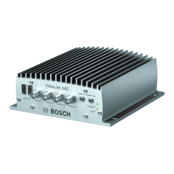
Page 16: Connections On The Front Panel
HDD LED flashes orange when hard drive activity is detected (only on units with a hard drive installed) DOC | V4.0 | 2009.06 Installation and Operating Manual Bosch Security Systems... -
Page 17: Connections On The Rear Panel
SFP slot for mini-GBIC module NOTICE! For more information about the LEDs, see Section 8.4 LEDs, page 113. For terminal block assignment, see Section 8.8 Terminal Block, page 115. Bosch Security Systems Installation and Operating Manual DOC | V4.0 | 2009.06... - Page 18 | Product Description VideoJet X40 DOC | V4.0 | 2009.06 Installation and Operating Manual Bosch Security Systems...
-
Page 19: Installation
For mounting on concrete, use screws with the following minimum specification: M4 × 40 mm (1.57 in) and 6 mm (0.23 in) plastic dowels, for example fischer S4, type 50106. Bosch Security Systems Installation and Operating Manual DOC | V4.0 | 2009.06... -
Page 20: Connections
Connect the VideoJet X40 to the network via the ETH 1 socket. Connect the VideoJet X40 to a redundant switch or hub on the same network via the ETH 2 socket. DOC | V4.0 | 2009.06 Installation and Operating Manual Bosch Security Systems... - Page 21 For ETH 1 or ETH 2 connections, use a UTP category 5 network cable with RJ45 plugs. NOTICE! You can obtain a list of compatible iSCSI systems from your supplier or directly from Bosch Security Systems. This list is constantly being updated and extended. CF Slot You can insert a type I or II CompactFlash card into the Compact Flash slot to enable recordings to be saved locally.
- Page 22 If possible, use a bounce-free contact system as the actuator. Connect the lines to the appropriate terminals on the orange terminal block (IN1 to IN4) and check that the connection is secure. DOC | V4.0 | 2009.06 Installation and Operating Manual Bosch Security Systems...
- Page 23 Connect the LED lines to the appropriate terminals on the orange terminal block (RM1 and RM2) and check that the connection is secure. Check that the signals on the Connect LED on the VideoJet X40 and the remote indicator LED correspond. Bosch Security Systems Installation and Operating Manual DOC | V4.0 | 2009.06...
- Page 24 Now check that the connections are secure. NOTICE! If you do not connect a battery to the unit, you should specify a time server to ensure correct system time. DOC | V4.0 | 2009.06 Installation and Operating Manual Bosch Security Systems...
-
Page 25: Power On/Power Off
Insert the CD into the computer's CD-ROM drive. If the CD does not start automatically, open the Configuration Manager directory using Windows Explorer and double-click Setup.exe. Follow the on-screen instructions. Bosch Security Systems Installation and Operating Manual DOC | V4.0 | 2009.06... - Page 26 Additional Parameters You can check and set additional parameters with the assistance of the Configuration Manager. You can find detailed information on this in the documentation for this program. DOC | V4.0 | 2009.06 Installation and Operating Manual Bosch Security Systems...
-
Page 27: Configuration Using A Web Browser
Insert the product CD into the computer's CD-ROM drive. If the CD does not start automatically, open the root directory of the CD in Windows Explorer and double-click MPEGAx.exe. Follow the on-screen instructions. Bosch Security Systems Installation and Operating Manual DOC | V4.0 | 2009.06... - Page 28 If you do not connect, the unit may have reached its maximum number of connections. Depending on the unit and network configuration, each VideoJet X40 can have up to 25 Web browser connections or up to 50 connections via VIDOS or Bosch Video Management System. DOC | V4.0 | 2009.06...
-
Page 29: Configuration Menu
The settings in the advanced mode should only be processed or modified by expert users or system support personnel. All settings are backed up in the VideoJet X40 memory so they are not lost even if the power fails. Bosch Security Systems Installation and Operating Manual DOC | V4.0 | 2009.06... - Page 30 CAUTION! Save each change with the associated Set button. Clicking the Set button saves the settings only in the current field. Changes in any other fields are ignored. DOC | V4.0 | 2009.06 Installation and Operating Manual Bosch Security Systems...
-
Page 31: Basic Mode: Unit Access
It will be displayed in the video screen if configured to do so (see Section Camera name stamping, page 41). The camera name makes the task of administering cameras in larger video monitoring systems easier, for example using the VIDOS or Bosch Video Management System programs. -
Page 32: Basic Mode: Date/Time
If necessary, you can synchronize the unit with your computer's system settings. Click the Sync to PC button to copy your computer's system time to the VideoJet X40. DOC | V4.0 | 2009.06 Installation and Operating Manual Bosch Security Systems... -
Page 33: Basic Mode: Network
If a DHCP server is employed in the network for the dynamic assignment of IP addresses, you can activate acceptance of IP addresses automatically assigned to the VideoJet X40. Certain applications (VIDOS, Bosch Video Management System, Archive Player, Configuration Manager) use the IP address for the unique assignment of the unit. If you use these... -
Page 34: Basic Mode: Encoder Profile
For ISDN connections via one B-channel, resolution 352 × 288/240 pixels – Modem For analog modem connections with 20 kbps, resolution 352 × 288/240 pixels – For GSM connections at 9,600 baud, resolution 176 × 144/120 pixels DOC | V4.0 | 2009.06 Installation and Operating Manual Bosch Security Systems... -
Page 35: Basic Mode: Audio
Line Out You can set the line output gain. Make sure that the display does not go beyond the green zone during modulation. Bosch Security Systems Installation and Operating Manual DOC | V4.0 | 2009.06... -
Page 36: Basic Mode: Recording
You can select all required text on this page with the mouse and copy it to the clipboard with the [Ctrl]+[C] key combination, for example if you want to send it via e-mail. DOC | V4.0 | 2009.06 Installation and Operating Manual Bosch Security Systems... -
Page 37: Advanced Mode: Identification
It will be displayed in the video screen if configured to do so (see Section Camera name stamping, page 41). The camera name makes the task of administering cameras in larger video monitoring systems easier, for example using the VIDOS or Bosch Video Management System programs. -
Page 38: Advanced Mode: Password
The lowest authorization level is live. It can only be used to view the live video image and switch between the different live image displays. DOC | V4.0 | 2009.06 Installation and Operating Manual Bosch Security Systems... -
Page 39: Advanced Mode: Date/Time
If you do not create a table, there will be no automatic switching. When changing and clearing individual entries, remember that two entries are usually related to each other and dependent on one another (switching to summer time and back to normal time). Bosch Security Systems Installation and Operating Manual DOC | V4.0 | 2009.06... -
Page 40: Advanced Mode: Display Stamping
Various overlays or "stamps" in the video image provide important supplementary information. These overlays can be enabled individually and are arranged on the image in a clear manner. NOTICE! The settings on this page apply to all camera inputs. DOC | V4.0 | 2009.06 Installation and Operating Manual Bosch Security Systems... - Page 41 Choose On if you wish the transmitted video images to be "watermarked". After activation, all images are marked with a green W. A red W indicates that the sequence (live or saved) has been manipulated. Bosch Security Systems Installation and Operating Manual DOC | V4.0 | 2009.06...
-
Page 42: Advanced Mode: Appearance
If you want to use the original graphics again, simply delete the entries in the Company logo and Device logo fields. JPEG size You can choose between two given image sizes to display the M-JPEG image on the LIVEPAGE. DOC | V4.0 | 2009.06 Installation and Operating Manual Bosch Security Systems... -
Page 43: Advanced Mode: Livepage Functions
Bilinx control Next to the field for view control at the top left of the LIVEPAGE, an additional field is displayed for the special Bosch Security Systems Bilinx control. Lease time (s) The lease time in seconds determines the time beyond which a different user is authorized to control the cameras after no further control signals are received from the current user. - Page 44 Enter the path for the storage location of individual images and video sequences that you can save from the LIVEPAGE. If necessary, click Browse to find a suitable directory. DOC | V4.0 | 2009.06 Installation and Operating Manual Bosch Security Systems...
-
Page 45: Advanced Mode: Logging
You can then view, edit and print this file with any text editor or the standard Office software. File for system log Enter the path for saving the system log here. If necessary, click Browse to find a suitable directory. Bosch Security Systems Installation and Operating Manual DOC | V4.0 | 2009.06... -
Page 46: Advanced Mode: Video Input
PLL as a result of jitter effects caused by the mechanical components of a VCR. NOTICE! In some cases, selecting the VCR option can lead to an improvement in the video image even with a camera connected. DOC | V4.0 | 2009.06 Installation and Operating Manual Bosch Security Systems... -
Page 47: Advanced Mode: Picture Settings
Also observe the processor load indicator that appears at the top of the window near the manufacturer's logo (see Section 8.6 Network Connection, page 114). Bosch Security Systems Installation and Operating Manual DOC | V4.0 | 2009.06... -
Page 48: Advanced Mode: Encoder Profile
You must set the parameters for each camera input and for each stream individually. The names Video 1 to Video 4 correspond to the labeling of the video inputs on the unit. DOC | V4.0 | 2009.06 Installation and Operating Manual Bosch Security Systems... - Page 49 Profile name You can enter a new name for the profile here. The name is then displayed in the list of available profiles in the Active profile field. Bosch Security Systems Installation and Operating Manual DOC | V4.0 | 2009.06...
- Page 50 I-frames are continuously generated. An entry of 2 indicates that only every second image is an I-frame, and 3 only every third image etc.; the frames in between are coded as P-frames. DOC | V4.0 | 2009.06 Installation and Operating Manual Bosch Security Systems...
- Page 51 JPEG images. The JPEG setting is suitable for applications that primarily require JPEG images, for example JPEG recordings. When this setting is made the amount of power available for video images will be reduced. Bosch Security Systems Installation and Operating Manual DOC | V4.0 | 2009.06...
-
Page 52: Advanced Mode: Audio
Selection Click one of the option boxes and then click Set to display the level of the respective audio input for orientation and to set the gain. DOC | V4.0 | 2009.06 Installation and Operating Manual Bosch Security Systems... -
Page 53: Advanced Mode: Storage Management
It is also possible to let the VRM Video Recording Manager control all recording when accessing an iSCSI system. This is an external program for configuring recording tasks for video servers. For further information please contact your local customer service at Bosch Security Systems. - Page 54 Rec. 1 stores Stream 1, Rec. 2 stores Stream 2. This means that you can record the standard data stream on a hard drive and record alarm images on the mobile CF card, for example. DOC | V4.0 | 2009.06 Installation and Operating Manual Bosch Security Systems...
-
Page 55: Advanced Mode: Remote Video Device
Once you have entered the IP address of the remote video device and saved it by pressing Set, the VideoJet X40 is then displayed for selection in the Storage Management for the remote video device. Bosch Security Systems Installation and Operating Manual DOC | V4.0 | 2009.06... -
Page 56: Advanced Mode: Recording Profiles
In each profile you can configure different settings for each camera input. NOTICE! You can change or add to the recording profile description on the tabs on the Recording Scheduler page (see Section Time periods, page 60). DOC | V4.0 | 2009.06 Installation and Operating Manual Bosch Security Systems... - Page 57 The numbering of the checkboxes for the alarm inputs corresponds to the labeling of the alarm inputs on the VideoJet X40. The motion and video loss alarm corresponds to the labeling on the video inputs. Bosch Security Systems Installation and Operating Manual DOC | V4.0 | 2009.06...
-
Page 58: Advanced Mode: Retention Time
Retention time Camera 1 to Retention time Camera 4 Enter the required retention time in hours or days for each recording. Recording 1 corresponds to Stream 1, Recording 2 corresponds to Stream 2. DOC | V4.0 | 2009.06 Installation and Operating Manual Bosch Security Systems... -
Page 59: Advanced Mode: Recording Scheduler
Click the Select All button to link all time intervals to the selected profile. Click the Clear All button to deselect all of the intervals. When you are finished, click the Set button to save the settings in the unit. Bosch Security Systems Installation and Operating Manual DOC | V4.0 | 2009.06... - Page 60 Recording status The graphic indicates the recording activity of the VideoJet X40. You will see an animated graphic while recording is taking place. DOC | V4.0 | 2009.06 Installation and Operating Manual Bosch Security Systems...
-
Page 61: Advanced Mode: Recording Status
Configuration Using a Web Browser | en 5.26 Advanced Mode: Recording Status Certain details on the recording status are displayed here for information purposes. You cannot change any of these settings. Bosch Security Systems Installation and Operating Manual DOC | V4.0 | 2009.06... -
Page 62: Advanced Mode: Alarm Connections
Destination IP address For each number, enter the corresponding IP address for the desired remote station. DOC | V4.0 | 2009.06 Installation and Operating Manual Bosch Security Systems... - Page 63 VIDOS or Bosch Video Management System, you can store a general password here. The VideoJet X40 can use this general password to connect to all remote stations protected with the same password.
- Page 64 Depending on the system configuration, the receiver can then select the other cameras as well. NOTICE! The numbering follows the labeling of the video inputs on the actual unit. DOC | V4.0 | 2009.06 Installation and Operating Manual Bosch Security Systems...
-
Page 65: Advanced Mode: Vca
Click one of the tabs to open the configuration of the corresponding video input. Select a VCA configuration and make the required settings. If necessary, click the Default button to return all settings to their default values. Bosch Security Systems Installation and Operating Manual DOC | V4.0 | 2009.06... -
Page 66: Advanced Mode: Vca Profiles
(see Section 8.6 Network Connection, page 114). Select a VCA profile and enter the required settings. If necessary, click the Default button to return all settings to their default values. DOC | V4.0 | 2009.06 Installation and Operating Manual Bosch Security Systems... - Page 67 NOTICE! Additional analysis algorithms with comprehensive functions such as IVMD and IVA are available from Bosch Security Systems. If you select one of these algorithms, you can set the corresponding parameters here directly. You can find information on this in the relevant documents on the product CD supplied.
- Page 68 This allows you to avoid false alarms triggered by short-term changes, for example cleaning activities in the direct field of vision of the camera. DOC | V4.0 | 2009.06 Installation and Operating Manual Bosch Security Systems...
- Page 69 Click Select Area to configure the sensor fields. A new window will open. If necessary, click Clear All first to clear the current selection (fields marked yellow). Bosch Security Systems Installation and Operating Manual DOC | V4.0 | 2009.06...
-
Page 70: Advanced Mode: Vca Scheduled
In addition to the normal weekdays, you can define holidays that are not in the standard weekly schedule on which recordings are to apply. This allows you to apply a schedule for Sundays to other days with dates that fall on varying weekdays. DOC | V4.0 | 2009.06 Installation and Operating Manual Bosch Security Systems... - Page 71 Click the date you wish to delete. Click OK. The item will be deleted from the table and the window will close. The process must be repeated for deleting additional days. Bosch Security Systems Installation and Operating Manual DOC | V4.0 | 2009.06...
-
Page 72: Advanced Mode: Vca Event Triggered
For more information, please see the Alarm Task Script Language document and the RCP+ documentation. You can find these documents on the product CD supplied (see Section 3.1 Scope of Delivery, page 11). DOC | V4.0 | 2009.06 Installation and Operating Manual Bosch Security Systems... -
Page 73: Advanced Mode: Audio Alarm
First set up normal audio transmission before you configure the audio alarm here (see Section 5.20 Advanced Mode: Audio, page 52). Audio alarm Select On if you want the unit to generate audio alarms from the input in question. Bosch Security Systems Installation and Operating Manual DOC | V4.0 | 2009.06... -
Page 74: Advanced Mode: Alarm E-Mail
VideoJet X40 Name The name makes it easier to identify the alarm in extensive video monitoring systems, for example with the VIDOS and Bosch Video Management System programs. Enter a unique and clear name here. CAUTION! Do not use any special characters, for example &, in the name. - Page 75 Test e-mail You can test the e-mail function by clicking the Send Now button. An alarm e-mail is immediately created and sent. Bosch Security Systems Installation and Operating Manual DOC | V4.0 | 2009.06...
-
Page 76: Advanced Mode: Alarm Task Editor
Script successfully parsed is displayed over the text field. If it was not successful, an error message will be displayed with further information. DOC | V4.0 | 2009.06 Installation and Operating Manual Bosch Security Systems... -
Page 77: Advanced Mode: Alarm Inputs
Idle state Select Open if you want the relay to operate as an NO contact, or select Closed if the relay is to operate as an NC contact. Bosch Security Systems Installation and Operating Manual DOC | V4.0 | 2009.06... - Page 78 The Livepage can also be configured to display the name under the relay icon. Trigger relay Click the button to trigger the relay manually (for testing or to operate a door opener, for example). DOC | V4.0 | 2009.06 Installation and Operating Manual Bosch Security Systems...
-
Page 79: Advanced Mode: Com1
The number of data bits per character cannot be changed. Stop bits Select the number of stop bits per character. Parity check Select the type of parity check. Bosch Security Systems Installation and Operating Manual DOC | V4.0 | 2009.06... -
Page 80: Advanced Mode: Network
Select the desired protocol for the serial interface. 5.38 Advanced Mode: Network The settings on this page are used to integrate the VideoJet X40 into an existing network. DOC | V4.0 | 2009.06 Installation and Operating Manual Bosch Security Systems... - Page 81 If a DHCP server is employed in the network for the dynamic assignment of IP addresses, you can activate acceptance of IP addresses automatically assigned to the VideoJet X40. Certain applications (VIDOS, Bosch Video Management System, Archive Player, Configuration Manager) use the IP address for the unique assignment of the unit. If you use these...
- Page 82 Information about the service, registration process and available host names can be found at DynDNS.org. Host name Enter the host name registered on DynDNS.org for the VideoJet X40 here. DOC | V4.0 | 2009.06 Installation and Operating Manual Bosch Security Systems...
-
Page 83: Advanced Mode: Advanced
Some changes only take effect after the unit is rebooted. In this case, the Set button changes to Set and Reboot. Make the desired changes. Click the Set and Reboot button. The VideoJet X40 is rebooted and the changed settings are activated. Bosch Security Systems Installation and Operating Manual DOC | V4.0 | 2009.06... - Page 84 If necessary, select a different port for the exchange of the RTSP data from the list. The standard RTSP port is 554. Select Off to deactivate the RTSP function. DOC | V4.0 | 2009.06 Installation and Operating Manual Bosch Security Systems...
-
Page 85: Advanced Mode: Multicasting
To enable simultaneous data reception on several receivers you need to activate the multicast function. To do this, check the box. You can then enter the multicast address. Bosch Security Systems Installation and Operating Manual DOC | V4.0 | 2009.06... -
Page 86: Advanced Mode: Jpeg Posting
Image size Select the resolution you wish the JPEG images to have: – Small 176 × 144/120 pixels (QCIF) – Medium 352 × 288/240 pixels (CIF) DOC | V4.0 | 2009.06 Installation and Operating Manual Bosch Security Systems... -
Page 87: Advanced Mode: Encryption
A special license, with which you will receive a corresponding activation key, is required to encrypt user data. You can enter the activation key to release the function on the Licenses page (see Section 5.44 Advanced Mode: Licenses, page 90). Bosch Security Systems Installation and Operating Manual DOC | V4.0 | 2009.06... -
Page 88: Advanced Mode: Maintenance
In the address bar of your browser, enter /main.htm after the IP address of the VideoJet X40 (for example 192.168.0.10/main.htm). Repeat the upload. DOC | V4.0 | 2009.06 Installation and Operating Manual Bosch Security Systems... - Page 89 You can download an internal maintenance log from the unit to send it to Customer Service for support purposes. Click Download and select a storage location for the file. Bosch Security Systems Installation and Operating Manual DOC | V4.0 | 2009.06...
-
Page 90: Advanced Mode: Licenses
You can select all required text on this page with the mouse and copy it to the clipboard with the [Ctrl]+[C] key combination, for example if you want to send it via e-mail. DOC | V4.0 | 2009.06 Installation and Operating Manual Bosch Security Systems... -
Page 91: Function Test
Does the VideoJet X40 transmit all the required data? – Does the VideoJet X40 respond to alarm events as required? – Do the recordings occur as intended? – Is it possible to control peripherals if necessary? Bosch Security Systems Installation and Operating Manual DOC | V4.0 | 2009.06... - Page 92 | Configuration Using a Web Browser VideoJet X40 DOC | V4.0 | 2009.06 Installation and Operating Manual Bosch Security Systems...
-
Page 93: Operation
Insert the product CD into the computer's CD-ROM drive. If the CD does not start automatically, open the root directory of the CD in Windows Explorer and double-click MPEGAx.exe. Follow the on-screen instructions. Bosch Security Systems Installation and Operating Manual DOC | V4.0 | 2009.06... - Page 94 Enter the IP address of the VideoJet X40 as the URL. The connection is established and after a short time you will see the LIVEPAGE with the video image. DOC | V4.0 | 2009.06 Installation and Operating Manual Bosch Security Systems...
-
Page 95: The Livepage
If you do not connect, the unit may have reached its maximum number of connections. Depending on the unit and network configuration, each VideoJet X40 can have up to 25 Web browser connections or up to 50 connections via VIDOS or Bosch Video Management System. Protected VideoJet X40... - Page 96 You can switch connected units using the relays in the VideoJet X40 (for example lights or door openers). To activate this, click the icon for the corresponding relay next to the video image. The icon will be red when the relay is activated. DOC | V4.0 | 2009.06 Installation and Operating Manual Bosch Security Systems...
- Page 97 When the connection maintaining voice contact with the VideoJet X40 is broken, the next user to make a connection to the VideoJet X40 can send audio data to the VideoJet X40. Bosch Security Systems Installation and Operating Manual DOC | V4.0 | 2009.06...
-
Page 98: Saving Snapshots
Click the icon again to stop recording. NOTICE! You can play back saved video sequences using the Player from Bosch Security Systems, which can be installed from the product CD supplied (see Section 3.1 Scope of Delivery, page 11). -
Page 99: Running Recording Program
You can ascertain from the Quad Video view for which camera a recording is running by moving the mouse cursor over the icon. A message is displayed below the mouse cursor. Bosch Security Systems Installation and Operating Manual DOC | V4.0 | 2009.06... -
Page 100: The Recordings Page
You will see a time bar below the video image for quick orientation. A green arrow above the bar indicates the position of the image currently being played back within the sequence. DOC | V4.0 | 2009.06 Installation and Operating Manual Bosch Security Systems... - Page 101 Bookmarks are only valid while you are in the RECORDINGS page; they are not saved with the sequences. As soon as you leave the page all bookmarks are deleted. Bosch Security Systems Installation and Operating Manual DOC | V4.0 | 2009.06...
-
Page 102: Installing The Player
Configuration Manager program. Installing the Player You can play back saved video sequences using the Player from Bosch Security Systems, which can be installed from the product CD supplied (see Section 3.1 Scope of Delivery, page 11). -
Page 103: Hardware Connections Between Video Servers
This option can also be used to connect a sender and a compatible receiver using a switch connected to the alarm input. You do not need a computer to make the connection in this case. Bosch Security Systems Installation and Operating Manual DOC | V4.0 | 2009.06... - Page 104 Start the terminal program and enter the command 4 in the main menu to switch to the Rcp+ menu. In the Rcp+ menu, enter the command 5 to deactivate the automatic connection. DOC | V4.0 | 2009.06 Installation and Operating Manual Bosch Security Systems...
-
Page 105: Operation Using Software Decoders
Bosch CCTV products as one component of an extensive video security management system. It allows you to integrate your existing components into a simple-to-control system or into the entire Bosch range, benefiting from a complete security solution based on the latest technology and years of experience. - Page 106 106 en | Operation VideoJet X40 DOC | V4.0 | 2009.06 Installation and Operating Manual Bosch Security Systems...
-
Page 107: Maintenance And Upgrades
Connect LED flashes red (see Section 3.4 Connections on the Front Panel, page 16). All settings will revert to their defaults. Change the IP address of the VideoJet X40 if necessary. Configure the unit to meet your requirements. Bosch Security Systems Installation and Operating Manual DOC | V4.0 | 2009.06... -
Page 108: Repairs
The VideoJet X40 should only be passed on together with this installation and operating manual. Your Bosch product is designed and manufactured with high-quality materials and components which can be recycled and reused. This symbol means that electrical and electronic equipment, at their end-of-life, should be disposed of separately from your household waste. -
Page 109: Appendix
If you are unable to resolve a malfunction, please contact your supplier or systems integrator, or go directly to Bosch Security Systems Customer Service. You can view a range of information about your unit version on the System Overview page (see Section 5.45 Advanced Mode: System Overview, page 90). -
Page 110: General Malfunctions
Audio configuration and LIVEPAGE Functions pages. The audio voice connection is Wait until the connection is free already in use by another and then call the sender again. receiver. DOC | V4.0 | 2009.06 Installation and Operating Manual Bosch Security Systems... - Page 111 CD. ActiveX components. Web browser contains Active proxy server in network. Create a rule in the local empty fields. computer's proxy settings to exclude local IP addresses. Bosch Security Systems Installation and Operating Manual DOC | V4.0 | 2009.06...
-
Page 112: Malfunctions With Iscsi Connections
LUN mapping is not Some iSCSI systems do not Delete the initiator extension on possible. support the use of an initiator the Identification configuration extension. page. DOC | V4.0 | 2009.06 Installation and Operating Manual Bosch Security Systems... -
Page 113: Leds
VideoJet X40 is faulty, for example following failed firmware upload. HDD LED Does not light up: No hard drive fitted. Lights up orange: Hard drive fitted. Flashes orange: Hard drive activity. Bosch Security Systems Installation and Operating Manual DOC | V4.0 | 2009.06... -
Page 114: Processor Load
The serial interface supports the RS-232, RS-422 and RS-485 transmission standards. The mode used depends on the current configuration (see Section 5.37 Advanced Mode: COM1, page 79). Connection is via the terminal block. DOC | V4.0 | 2009.06 Installation and Operating Manual Bosch Security Systems... -
Page 115: Terminal Block
For the RM1 and RM2 contact specifications, see Section Remote Indication of the Connection Status, page 23. For the backup power supply specifications, see Section Backup Power Supply, page 24. Bosch Security Systems Installation and Operating Manual DOC | V4.0 | 2009.06... -
Page 116: Communication With Terminal Program
When you have entered a value, such as the IP address, check the characters you have entered before pressing Enter to transfer the values to the VideoJet X40. DOC | V4.0 | 2009.06 Installation and Operating Manual Bosch Security Systems... - Page 117 Additional Parameters You can use the terminal program to check other basic parameters and modify them where necessary. Use the on-screen commands in the various submenus to do this. Bosch Security Systems Installation and Operating Manual DOC | V4.0 | 2009.06...
-
Page 118: Copyrights
Corporation not be used in advertising or publicity pertaining to distribution of the software without specific, written prior permission. This software is based in part on the work of the Independent JPEG Group. DOC | V4.0 | 2009.06 Installation and Operating Manual Bosch Security Systems... -
Page 119: Specifications
Dimensions (H × W × D) 61 × 160 × 178 mm / 2.4 × 6.3 × 7.0 in, including BNC connections Weight Approx. 1.5 kg / 3.3 lb, including HDD Bosch Security Systems Installation and Operating Manual DOC | V4.0 | 2009.06... -
Page 120: Protocols/Standards
4 cameras 2 cameras 1 camera 4CIF 12.5/15 ips 25/30 ips 25/30 ips 2/3 D1 25/30 ips 25/30 ips 25/30 ips 2CIF 25/30 ips 25/30 ips 25/30 ips DOC | V4.0 | 2009.06 Installation and Operating Manual Bosch Security Systems... -
Page 121: Glossary
Unit of measurement for the speed of data transmission Bits per second, the actual data rate BVIP Bosch Video over IP unit CompactFlash; interface standard, for digital storage media amongst other things. Used in computers in the form of CF cards, digital cameras and Personal Digital Assistants (PDA). - Page 122 Management Information Base; a collection of information for remote servicing using the SNMP protocol MPEG-2 Improved video/audio compression standard, compression on highest level allows images in studio quality; now established as broadcast standard DOC | V4.0 | 2009.06 Installation and Operating Manual Bosch Security Systems...
- Page 123 Storage Networking Industry Association; association of companies for defining the iSCSI standard SNMP Simple Network Management Protocol; a protocol for network management, for managing and monitoring network components Bosch Security Systems Installation and Operating Manual DOC | V4.0 | 2009.06...
- Page 124 User Datagram Protocol Uniform Resource Locator Unshielded Twisted Pair See Wide Area Network Wide Area Network A long distance link used to extend or connect remotely located local area networks DOC | V4.0 | 2009.06 Installation and Operating Manual Bosch Security Systems...
-
Page 125: Index
Licenses 90 Default 50 Live video images 27 Default profile 50 Livepage 43 Deleting recordings 55 Low Voltage Directive 8 Device ID 37 Low-pass filter 47 Device name 31 Bosch Security Systems Installation and Operating Manual DOC | V4.0 | 2009.06... - Page 126 Time 24 Recording media 54 Time server 33 Recording profiles 56 Time server IP address 33 Recording program 99 Time server protocol 33 Recording scheduler 59 Time signal 33 DOC | V4.0 | 2009.06 Installation and Operating Manual Bosch Security Systems...
- Page 127 Unit time 32 URL 28 USB interface 16 User name 32 Value 47 VCR 46 Video content analysis 65 Video input 46 Video sensor 65 VRM 53 Watermarking 41 Bosch Security Systems Installation and Operating Manual DOC | V4.0 | 2009.06...
- Page 128 128 en | Index VideoJet X40 DOC | V4.0 | 2009.06 Installation and Operating Manual Bosch Security Systems...
- Page 130 Bosch Sicherheitssysteme GmbH Robert-Koch-Straße 100 85521 Ottobrunn Germany Telefon 089 6290-0 089 6290-1020 www.boschsecurity.com © Bosch Sicherheitssysteme GmbH, 2009...