Table of Contents
Advertisement
Quick Links
Advertisement
Table of Contents

Related Manuals for Asus Vintage-PH1


Summary of Contents for Asus Vintage-PH1
- Page 1 Vintage-PH1 Barebone System...
- Page 2 Product warranty or service will not be extended if: (1) the product is repaired, modified or altered, unless such repair, modification of alteration is authorized in writing by ASUS; or (2) the serial number of the product is defaced or missing.
-
Page 3: Table Of Contents
Table of contents Notices ....................vii Safety information ................vii About this guide ................viii System package contents ..............x Chapter 1: System Introduction Chapter 1: System Introduction Chapter 1: System Introduction Chapter 1: System Introduction Chapter 1: System Introduction Welcome! ................ - Page 4 Creating a bootable floppy disk ......5-2 5.1.2 ASUS EZ Flash utility ..........5-3 5.1.3 AFUDOS utility ............5-4 5.1.4 ASUS CrashFree BIOS 2 utility ........ 5-6 5.1.5 ASUS Update utility ..........5-8 BIOS setup program ............5-11 5.2.1 BIOS menu screen ..........5-12 5.2.2...
- Page 5 Table of contents Main menu ................5-14 5.3.1 System Time ............5-14 5.3.2 System Date ............5-14 5.3.3 Legacy Diskette A ..........5-14 5.3.4 Primary, Third, and Fourth IDE Master/Slave ..5-15 5.3.5 IDE Configuration ..........5-16 5.3.6 System Information ..........5-17 Advanced menu ..............
-
Page 6: Notices
Notices Federal Communications Commission Statement Federal Communications Commission Statement Federal Communications Commission Statement Federal Communications Commission Statement Federal Communications Commission Statement This device complies with Part 15 of the FCC Rules. Operation is subject to the following two conditions: • This device may not cause harmful interference, and •... -
Page 7: Safety Information
Safety information Electrical safety Electrical safety Electrical safety Electrical safety Electrical safety • To prevent electrical shock hazard, disconnect the power cable from the electrical outlet before relocating the system. • When adding or removing devices to or from the system, ensure that the power cables for the devices are unplugged before the signal cables are connected. -
Page 8: About This Guide
C h a p t e r 1 : S y s t e m i n t r o d u c t i o n This chapter gives a general description of the ASUS Vintage-PH1. The chapter lists the system features, including introduction on the front and rear panel, and internal components. - Page 9 A S U S W e b s i t e s A S U S W e b s i t e s The ASUS websites worldwide provide updated information on ASUS hardware and software products. Refer to the ASUS contact information.
-
Page 10: System Package Contents
System package contents Check your Vintage-PH1 system package for the following items. If any of the items is damaged or missing, contact your retailer immediately. I t e m d e s c r i p t i o n... - Page 11 Chapter 1 This chapter gives a general description of the ASUS Vintage-PH1. The chapter lists the system features including introduction on the front and rear panel, and internal components. A S U S V i n t a g e - P H 1...
-
Page 12: Chapter 1: System Introduction
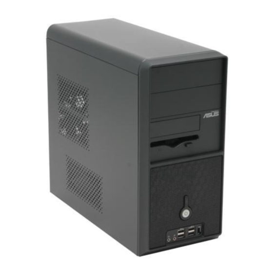
Thank you for choosing the ASUS Vintage-PH1! The ASUS Vintage-PH1 is an all-in-one barebone system with a versatile home entertainment feature. The system comes in a stylish mini-tower casing and powered by the ASUS motherboard that supports the Intel ®... -
Page 13: Turning Off The Power
1 . 1 . T w o e m p t y 5 . 2 5 - i n c h b a y s T w o e m p t y 5 . 2 5 - i n c h b a y s T w o e m p t y 5 . -
Page 14: Rear Panel
Rear panel The system rear panel includes the power connector and several I/O ports that allow convenient connection of devices. 1 . 1 . P S / 2 m o u s e p o r t P S / 2 m o u s e p o r t P S / 2 m o u s e p o r t P S / 2 m o u s e p o r t P S / 2 m o u s e p o r t. -
Page 15: Expansion Cards
1 0 . 1 0 . L i n e I n p o r t ( l i g h t b l u e ) . 1 0 . L i n e I n p o r t ( l i g h t b l u e ) . L i n e I n p o r t ( l i g h t b l u e ) . -
Page 16: Voltage Selector
Voltage selector Voltage selector Voltage selector Voltage selector Voltage selector The PSU has a 115 V/230 V voltage selector switch located beside the power connector. Use this switch to select the appropriate system input voltage according to the voltage supply in your area. If the voltage supply in your area is 100-127 V, set the switch to 115 V. -
Page 17: Internal Components
1 1 1 1 1 1 1 1 1 1 5.25-inch empty optical drive bay Floppy disk drive bay Front panel cover Hard disk drive metal tray Chassis fan ASUS motherboard DIMM sockets LGA775 socket with PnP cap PCI Express™ x16 slot for discrete graphics card 10. PCI slots 11. - Page 18 1 - 8 1 - 8 C h a p t e r 1 : S y s t e m i n t r o d u c t i o n C h a p t e r 1 : S y s t e m i n t r o d u c t i o n 1 - 8 1 - 8 1 - 8...
- Page 19 Chapter 2 This chapter provides step-by-step instructions on how to install components in the system. A S U S V i n t a g e - P H 1 A S U S V i n t a g e - P H 1 A S U S V i n t a g e - P H 1 A S U S V i n t a g e - P H 1 A S U S V i n t a g e - P H 1...
-
Page 20: Chapter 2: Basic Installation
Preparation Before you proceed, make sure that you have all the components you plan to install in the system. Basic components to install Basic components to install Basic components to install Basic components to install Basic components to install 1. Central processing unit (CPU) 2. -
Page 21: Removing The Side Plate And
Removing the side plate and front cover The system has two chassis side plates, each one secured by two screws located on the rear panel. To remove the chassis side plate: Turn each screw Screw counterclockwise to release the side cover. Set the screws aside. - Page 22 Swing the left edge of the front panel outward. Unhook the hinge-like tabs from the holes on the right side of the front panel to completely detach the front panel assembly from the chassis. H i n g e - l i k e t a b H i n g e - l i k e t a b H i n g e - l i k e t a b H i n g e - l i k e t a b...
-
Page 23: Central Processing Unit (Cpu)
• Keep the cap after installing the motherboard. ASUS will process Return Merchandise Authorization (RMA) requests only if the motherboard comes with the cap on the LGA775 socket. - Page 24 Press the load lever with your thumb (A) and move it to the left (B) until it is released from the retention tab. P n P C a p P n P C a p P n P C a p P n P C a p P n P C a p R e t e n t i o n t a b...
- Page 25 Close the load plate (A), then push the load lever (B) until it snaps into the retention tab. The CPU fits in only one correct orientation. DO NOT force the CPU into the socket to prevent bending the connectors on the socket and damaging the CPU! Notes on Intel Notes on Intel...
-
Page 26: Installling The Cpu Heatsink And Fan
2.4.2 2.4.2 2.4.2 2.4.2 2.4.2 Installling the CPU heatsink and fan Installling the CPU heatsink and fan Installling the CPU heatsink and fan Installling the CPU heatsink and fan Installling the CPU heatsink and fan The Intel ® Pentium ® 4 LGA775 processor requires a specially designed heatsink and fan assembly to ensure optimum thermal condition and performance. - Page 27 Push down two fasteners at a time in a diagonal sequence to secure the heatsink and fan assembly in place. When the fan and heatsink assembly is in place, connect the CPU fan cable to the connector on the motherboard labeled CPU_FAN1. CPU_FAN1 ®...
-
Page 28: Uninstalling The Cpu Heatsink And Fan
2.4.3 2.4.3 2.4.3 Uninstalling the CPU heatsink and fan Uninstalling the CPU heatsink and fan Uninstalling the CPU heatsink and fan 2.4.3 2.4.3 Uninstalling the CPU heatsink and fan Uninstalling the CPU heatsink and fan To uninstall the CPU heatsink and fan: Disconnect the CPU fan cable from the connector on the motherboard labeled... - Page 29 Remove the heatsink and fan assembly from the motherboard. Rotate each fastener clockwise to reset the orientation. When reset, each fastener should be oriented as shown, with the narrow groove directed outward. A S U S V i n t a g e - P H 1 A S U S V i n t a g e - P H 1 2 - 1 1 2 - 1 1...
-
Page 30: Installing A Dimm
Installing a DIMM The system motherboard comes with two Double Data Rate (DDR) Dual Inline Memory Module (DIMM) sockets. The following figure illustrates the location of the sockets: ® 184-Pin DDR DIMM Sockets 2.5.1 2.5.1 Memory configurations Memory configurations 2.5.1 2.5.1 2.5.1 Memory configurations... - Page 31 C C C C C - supports four modules inserted into the blue and black slots as two pairs of Dual-channel memory configuration. Visit the ASUS website (www.asus.com) for the latest DDR Qualified Vendors List. A S U S V i n t a g e - P H 1...
-
Page 32: Removing A Dimm
2.5.2 2.5.2 2.5.2 2.5.2 2.5.2 Installing a DIMM Installing a DIMM Installing a DIMM Installing a DIMM Installing a DIMM Make sure to unplug the power supply before adding or removing DIMMs or other system components. Failure to do so may cause severe damage to both the motherboard and the components. -
Page 33: Expansion Slots
Expansion slots In the future, you may need to install expansion cards. The following sub-sections describe the slots and the expansion cards that they support. Make sure to unplug the power cord before adding or removing expansion cards. Failure to do so may cause you physical injury and damage motherboard components. - Page 34 Standard interrupt assignments Standard interrupt assignments Standard interrupt assignments Standard interrupt assignments Standard interrupt assignments I R Q I R Q I R Q P r i o r i t y P r i o r i t y P r i o r i t y S t a n d a r d F u n c t i o n S t a n d a r d F u n c t i o n...
-
Page 35: Pci Slots
2.6.3 2.6.3 2.6.3 2.6.3 2.6.3 PCI slots PCI slots PCI slots PCI slots PCI slots The PCI slots support cards such as a LAN card, SCSI card, USB card, and other cards that comply with PCI specifications. The figure shows a LAN card installed on a PCI slot. -
Page 36: Installing An Optical Drive
Installing an optical drive Follow these steps to install a CD-ROM drive. Place the chassis upright. Insert the CD-ROM drive into the upper 5.25-inch drive bay. Carefully push the CD-ROM drive into the bay until its screw holes align with the holes on the bay as shown. - Page 37 Connect a power cable from the power supply to the power connector at the back of the CD-ROM. Use the cable with the white connector. Connect one end of the IDE ribbon cable to the IDE interface at the back of the CD-ROM, matching the red stripe on the cable with Pin 1 on the IDE interface.
-
Page 38: Installing A Hard Disk Drive
Installing a hard disk drive The chassis has one 3.5-inch hard disk drive (HDD) bay right under the 5.25-inch bay. The following figures show the internal and external views of the HDD bay location. E x t e r n a l v i e w E x t e r n a l v i e w I n t e r n a l v i e w I n t e r n a l v i e w... -
Page 39: Ide Interface
Connect a power cable from the power supply to the power connector at the back of the HDD. Use the cable with the white connector. Connect the IDE hard disk ribbon cable to the IDE interface at the back of the HDD, matching the red stripe on the cable with Pin 1 on the IDE interface. -
Page 40: Installing A Floppy Disk Drive
Installing a floppy disk drive The Vintage-PH1 system comes with one 3.25-inch drive bay for a floppy disk drive. To install a floppy disk drive: Remove the front panel cover. For instructions on how to remove the front panel cover, refer to page 2-3 of section “2.3 Removing the side plate and front cover”... -
Page 41: 2.10 Re-Connecting Cables
2.10 Re-connecting cables You may have disconnected some cables when you were installing components. You must re-connect these cables before you replace the chassis cover. LED cables LED cables LED cables LED cables LED cables R e s e t b u t t o n R e s e t b u t t o n R e s e t b u t t o n R e s e t b u t t o n... -
Page 42: Replacing The Side Plate And
2.11 Replacing the side plate and front cover After you have installed all the internal components and you have connected all the necessary cables, you are now ready to put the system back together. Hook the hinge-like tabs to the holes on the right side of the front panel to attach the front panel assembly to the chassis. - Page 43 Fit the rail tabs on the side plate into the locking tab holes in the chassis. L o c k i n g L o c k i n g L o c k i n g L o c k i n g L o c k i n g t a b h o l e t a b h o l e...
-
Page 44: 2.13 Connecting External Devices
2.13 Connecting external devices The figure below shows the specific connectors and devices that you can connect to the rear panel ports. PS/2 KB Serial PS/2 Mouse Parallel RJ-45 IEEE 1394 Center/ Subwoofer Side Speaker Rear Speaker Line In Line Out 2 - 2 6 2 - 2 6 C h a p t e r 2 : B a s i c i n s t a l l a t i o n... - Page 45 Chapter 3 This chapter helps you power up the system and install drivers and utilities from the support CD. A S U S V i n t a g e - P H 1 A S U S V i n t a g e - P H 1 A S U S V i n t a g e - P H 1 A S U S V i n t a g e - P H 1 A S U S V i n t a g e - P H 1...
-
Page 46: Chapter 3: Starting Up
• The contents of the support CD are subject to change at any time without notice. Visit the ASUS website for updates. 3 - 2 3 - 2 C h a p t e r 3 : S t a r t i n g u p... -
Page 47: Running The Support Cd
3.3.1 3.3.1 3.3.1 3.3.1 3.3.1 Running the support CD Running the support CD Running the support CD Running the support CD Running the support CD To begin using the support CD, place the CD in your optical drive. The CD automatically displays the D r i v e r s D r i v e r s D r i v e r s... -
Page 48: Utilities Menu
Utilities menu Utilities menu Utilities menu The Utilities menu shows the applications and other software that the motherboard supports. ASUS PC Probe ASUS PC Probe ASUS PC Probe ASUS PC Probe ASUS PC Probe This smart utility monitors the fan speed, CPU temperature, and system voltages, and alerts you of any detected problems. -
Page 49: Asus Contact Information
Click the C o n t a c t C o n t a c t C o n t a c t tab to display the ASUS contact information. You can also find this information on the inside front cover of this user guide. - Page 50 3 - 6 3 - 6 C h a p t e r 3 : S t a r t i n g u p C h a p t e r 3 : S t a r t i n g u p 3 - 6 3 - 6 3 - 6...
- Page 51 Chapter 4 This chapter gives information about the motherboard that comes with the system. This chapter includes the motherboard layout, jumper settings, and connector locations. A S U S V i n t a g e - P H 1 A S U S V i n t a g e - P H 1 A S U S V i n t a g e - P H 1 A S U S V i n t a g e - P H 1...
-
Page 52: Chapter 4: Motherboard Info
Introduction The Vintage-PH1 barebone system comes with an ASUS motherboard. This chapter provides technical information about the motherboard for future upgrades or system reconfiguration. Motherboard layout KBPWR1 PS/2KBMS CHA_FAN1 T: Mouse B: Keyboard CPU_FAN1 COM1 ATX12V1 FANPWR1 LGA775 VGA1 F_USB12... -
Page 53: Jumpers
Jumpers 1 . 1 . C l e a r R T C R A M ( C L R T C ) C l e a r R T C R A M ( C L R T C ) C l e a r R T C R A M ( C L R T C ) C l e a r R T C R A M ( C L R T C ) C l e a r R T C R A M ( C L R T C ) - Page 54 2 . 2 . U S B d e v i c e w a k e - u p ( 3 - p i n U S B P W 1 2 , U S B P W 3 4 , U S B d e v i c e w a k e - u p ( 3 - p i n U S B P W 1 2 , U S B P W 3 4 , U S B d e v i c e w a k e - u p ( 3 - p i n U S B P W 1 2 , U S B P W 3 4 , U S B d e v i c e w a k e - u p ( 3 - p i n U S B P W 1 2 , U S B P W 3 4 ,...
- Page 55 4 . 4 . F a n p o w e r ( 3 - p i n F A N P W R 1 ) F a n p o w e r ( 3 - p i n F A N P W R 1 ) F a n p o w e r ( 3 - p i n F A N P W R 1 ) F a n p o w e r ( 3 - p i n F A N P W R 1 ) F a n p o w e r ( 3 - p i n F A N P W R 1 )
-
Page 56: Connectors
Connectors 1 . 1 . F l o p p y d i s k d r i v e c o n n e c t o r ( 3 4 - 1 p i n F L O P P Y 1 ) F l o p p y d i s k d r i v e c o n n e c t o r ( 3 4 - 1 p i n F L O P P Y 1 ) F l o p p y d i s k d r i v e c o n n e c t o r ( 3 4 - 1 p i n F L O P P Y 1 ) F l o p p y d i s k d r i v e c o n n e c t o r ( 3 4 - 1 p i n F L O P P Y 1 ) -
Page 57: Hard Disk Drives
4 . 4 . S e r i a l A T A c o n n e c t o r s S e r i a l A T A c o n n e c t o r s S e r i a l A T A c o n n e c t o r s S e r i a l A T A c o n n e c t o r s S e r i a l A T A c o n n e c t o r s... - Page 58 5 . 5 . C P U a n d C h a s s i s F a n c o n n e c t o r s C P U a n d C h a s s i s F a n c o n n e c t o r s C P U a n d C h a s s i s F a n c o n n e c t o r s C P U a n d C h a s s i s F a n c o n n e c t o r s C P U a n d C h a s s i s F a n c o n n e c t o r s...
- Page 59 6 . 6 . U S B c o n n e c t o r s ( 1 0 - 1 p i n U S B 5 6 , U S B 7 8 ) U S B c o n n e c t o r s ( 1 0 - 1 p i n U S B 5 6 , U S B 7 8 ) U S B c o n n e c t o r s ( 1 0 - 1 p i n U S B 5 6 , U S B 7 8 ) U S B c o n n e c t o r s ( 1 0 - 1 p i n U S B 5 6 , U S B 7 8 ) U S B c o n n e c t o r s ( 1 0 - 1 p i n U S B 5 6 , U S B 7 8 )
- Page 60 7 . 7 . A T X p o w e r c o n n e c t o r s ( 2 4 - p i n E A T X P W R 1 , A T X p o w e r c o n n e c t o r s ( 2 4 - p i n E A T X P W R 1 , A T X p o w e r c o n n e c t o r s ( 2 4 - p i n E A T X P W R 1 , A T X p o w e r c o n n e c t o r s ( 2 4 - p i n E A T X P W R 1 , A T X p o w e r c o n n e c t o r s ( 2 4 - p i n E A T X P W R 1 ,...
- Page 61 8 . 8 . O p t i c a l d r i v e a u d i o c o n n e c t o r ( 4 - p i n C D 1 ) O p t i c a l d r i v e a u d i o c o n n e c t o r ( 4 - p i n C D 1 ) O p t i c a l d r i v e a u d i o c o n n e c t o r ( 4 - p i n C D 1 ) O p t i c a l d r i v e a u d i o c o n n e c t o r ( 4 - p i n C D 1 )
- Page 62 1 0 . 1 0 . 1 0 . C h a s s i s i n t r u s i o n c o n n e c t o r ( 4 - 1 p i n C H A S S I S 1 ) 1 0 .
- Page 63 1 2 . 1 2 . D i g i t a l a u d i o c o n n e c t o r ( 4 - 1 p i n S P D I F _ O U T 1 ) D i g i t a l a u d i o c o n n e c t o r ( 4 - 1 p i n S P D I F _ O U T 1 ) 1 2 .
- Page 64 1 4 . 1 4 . 1 4 . S y s t e m p a n e l c o n n e c t o r ( 1 0 - 1 p i n F _ P A N E L 1 ) S y s t e m p a n e l c o n n e c t o r ( 1 0 - 1 p i n F _ P A N E L 1 ) S y s t e m p a n e l c o n n e c t o r ( 1 0 - 1 p i n F _ P A N E L 1 ) S y s t e m p a n e l c o n n e c t o r ( 1 0 - 1 p i n F _ P A N E L 1 )
- Page 65 Chapter 5 This chapter tells how to change system settings through the BIOS Setup menus and describes the BIOS parameters. A S U S V i n t a g e - P H 1 A S U S V i n t a g e - P H 1 A S U S V i n t a g e - P H 1 A S U S V i n t a g e - P H 1 A S U S V i n t a g e - P H 1...
-
Page 66: Managing And Updating Your Bios
Refer to the corresponding sections for details on these utilities. Save a copy of the original motherboard BIOS file to a bootable floppy disk in case you need to restore the BIOS in the future. Copy the original motherboard BIOS using the ASUS Update or AFUDOS utilities. 5.1.1 5.1.1 5.1.1... -
Page 67: Asus Ez Flash Utility
ASUS EZ Flash utility ASUS EZ Flash utility The ASUS EZ Flash feature allows you to update the BIOS without having to go through the long process of booting from a floppy disk and using a DOS-based utility. The EZ Flash utility is built-in the BIOS chip so it is accessible by pressing <Alt>... -
Page 68: Afudos Utility
5.1.3 5.1.3 AFUDOS utility AFUDOS utility 5.1.3 5.1.3 5.1.3 AFUDOS utility AFUDOS utility AFUDOS utility The AFUDOS utility allows you to update the BIOS file in DOS environment using a bootable floppy disk with the updated BIOS file. This utility also allows you to copy the current BIOS file that you can use as backup when the BIOS fails or gets corrupted during the updating process. - Page 69 Updating the BIOS file To update the BIOS file using the AFUDOS utility: Visit the ASUS website (www.asus.com) and download the latest BIOS file for the motherboard. Save the BIOS file to a bootable floppy disk. Write the BIOS filename on a piece of paper. You need to type the exact BIOS filename at the DOS prompt.
-
Page 70: Asus Crashfree Bios 2 Utility
ASUS CrashFree BIOS 2 utility ASUS CrashFree BIOS 2 utility The ASUS CrashFree BIOS 2 is an auto recovery tool that allows you to restore the BIOS file when it fails or gets corrupted during the updating process. You can update a corrupted BIOS file using the motherboard support CD or the floppy disk that contains the updated BIOS file. - Page 71 The utility displays the following message and automatically checks the floppy disk for the original or updated BIOS file. Bad BIOS checksum. Starting BIOS recovery... Checking for floppy... When found, the utility reads the BIOS file and starts flashing the corrupted BIOS file.
-
Page 72: Asus Update Utility
5.1.5 5.1.5 ASUS Update utility ASUS Update utility ASUS Update utility The ASUS Update is a utility that allows you to manage, save, and update the motherboard BIOS in Windows ® environment. The ASUS Update utility allows you to: •... - Page 73 Updating the BIOS through the Internet Updating the BIOS through the Internet Updating the BIOS through the Internet To update the BIOS through the Internet: Launch the ASUS Update utility from the Windows ® desktop by clicking S t a r t...
- Page 74 A S U S U p d a t e A S U S U p d a t e. The ASUS Update main window appears. U p d a t e B I O S f r o m a...
-
Page 75: Bios Setup Program
• Visit the ASUS website (www.asus.com) to download the latest BIOS file for this motherboard. A S U S V i n t a g e - P H 1... -
Page 76: Bios Menu Screen
5.2.1 5.2.1 5.2.1 5.2.1 5.2.1 BIOS menu screen BIOS menu screen BIOS menu screen BIOS menu screen BIOS menu screen M e n u i t e m s M e n u i t e m s M e n u b a r M e n u b a r C o n f i g u r a t i o n f i e l d s C o n f i g u r a t i o n f i e l d s... -
Page 77: Menu Items
5.2.4 5.2.4 Menu items Menu items 5.2.4 5.2.4 5.2.4 Menu items Menu items Menu items The highlighted item on the menu Use [ENTER], [TAB] bar displays the specific items for System Time [11:51:19] or [SHIFT-TAB] to System Date [Thu 06/10/2004] select a field. -
Page 78: Main Menu
Main menu When you enter the BIOS Setup program, the Main menu screen appears, giving you an overview of the basic system information. Refer to section “5.2.1 BIOS menu screen” for information on the menu screen items and how to navigate through them. Use [ENTER], [TAB] or System Time [11:51:19]... -
Page 79: Primary, Third, And Fourth Ide Master/Slave
5.3.4 5.3.4 Primary, Third, and Fourth IDE Master/Slave Primary, Third, and Fourth IDE Master/Slave 5.3.4 5.3.4 5.3.4 Primary, Third, and Fourth IDE Master/Slave Primary, Third, and Fourth IDE Master/Slave Primary, Third, and Fourth IDE Master/Slave While entering Setup, the BIOS automatically detects the presence of IDE devices. -
Page 80: Ide Configuration
PIO Mode [Auto] PIO Mode [Auto] PIO Mode [Auto] PIO Mode [Auto] PIO Mode [Auto] Selects the PIO mode. Configuration options: [Auto] [0] [1] [2] [3] [4] DMA Mode [Auto] DMA Mode [Auto] DMA Mode [Auto] DMA Mode [Auto] DMA Mode [Auto] Selects the DMA mode. -
Page 81: System Information
Enhanced Mode Support On [SATA mode] The default setting SATA allows you to use native OS on Serial ATA and Parallel ATA ports. We recommend that you do not change the default setting for better OS compatibility. In this setting, you may use legacy OS on the Parallel ATA ports o n l y i f o n l y i f o n l y i f... -
Page 82: Advanced Menu
Advanced menu The Advanced menu items allow you to change the settings for the CPU and other system devices. Take caution when changing the settings of the Advanced menu items. Incorrect field values can cause the system to malfunction. Configure the USB USB Configuration support. -
Page 83: Cpu Configuration
Legacy USB Support [Auto] Legacy USB Support [Auto] Legacy USB Support [Auto] Legacy USB Support [Auto] Legacy USB Support [Auto] Allows you to enable or disable support for USB devices on legacy operating systems (OS). Setting to Auto allows the system to detect the presence of USB devices at startup. -
Page 84: Chipset
Microcode Updation [Enabled] Microcode Updation [Enabled] Microcode Updation [Enabled] Microcode Updation [Enabled] Microcode Updation [Enabled] Enables or disables microcode updation. Configuration options: [Disabled] [Enabled] Max CPUID Value Limit [Disabled] Max CPUID Value Limit [Disabled] Max CPUID Value Limit [Disabled] Max CPUID Value Limit [Disabled] Max CPUID Value Limit [Disabled] Enable this item to boot legacy operating systems that cannot support CPUs with extended CPUID functions. - Page 85 Advanced Chipset Settings Advanced Chipset Settings Advanced Chipset Settings Advanced Chipset Settings Advanced Chipset Settings Configure DRAM Timing by SPD [Enabled] When this item is enabled, the DRAM timing parameters are set according to the DRAM SPD (Serial Presence Detect). When disabled, you can manually set the DRAM timing parameters through the DRAM sub-items.
-
Page 86: Onboard Devices Configuration
5.4.4 5.4.4 Onboard Devices Configuration Onboard Devices Configuration 5.4.4 5.4.4 5.4.4 Onboard Devices Configuration Onboard Devices Configuration Onboard Devices Configuration Configure Win627EHF Super IO Chipset Enable or disable Azalia controller. Azalia Controller [Enabled] Onboard 1394 Controller [Enabled] Onboard LAN Boot ROM [Disabled] Serial Port1 Address [3F8/IRQ4]... -
Page 87: Pci Pnp
Parallel Port Mode [ECP] Parallel Port Mode [ECP] Parallel Port Mode [ECP] Parallel Port Mode [ECP] Parallel Port Mode [ECP] Allows you to select the Parallel Port mode. Configuration options: [Normal] [Bi-directional] [EPP] [ECP] ECP Mode DMA Channel [DMA3] Appears only when the Parallel Port Mode is set to [ECP]. This item allows you to set the Parallel Port ECP DMA. - Page 88 Plug and Play O/S [No] Plug and Play O/S [No] Plug and Play O/S [No] Plug and Play O/S [No] Plug and Play O/S [No] When set to [No], BIOS configures all the devices in the system. When set to [Yes] and if you install a Plug and Play operating system, the operating system configures the Plug and Play devices not required for boot.
-
Page 89: Power Menu
Power menu The Power menu items allow you to change the settings for the Advanced Power Management (APM) and Advanced Configuration and Power Interface (ACPI). Select an item then press <Enter> to display the configuration options. Select the ACPI state Suspend Mode [Auto] used for System... -
Page 90: Apm Configuration
5.5.5 5.5.5 APM Configuration APM Configuration 5.5.5 5.5.5 5.5.5 APM Configuration APM Configuration APM Configuration APM Configuration <Enter> to select whether or not to Restore on AC Power Loss [Power Off] restart the system Power On By RTC Alarm [Disabled] after AC power loss. -
Page 91: Hardware Monitor
Power On By PS/2 Keyboard [Disabled] Power On By PS/2 Keyboard [Disabled] Power On By PS/2 Keyboard [Disabled] Power On By PS/2 Keyboard [Disabled] Power On By PS/2 Keyboard [Disabled] Allows you to use specific keys on the keyboard to turn on the system. This feature requires an ATX power supply that provides at least 1A on the +5VSB lead. - Page 92 CPU Q-Fan Control [Enabled] CPU Q-Fan Control [Enabled] Allows you to enable or disable the ASUS Q-Fan feature that smartly adjusts the fan speeds for more efficient system operation. When this field C P U F a n R a t i o...
-
Page 93: Boot Menu
Boot menu The Boot menu items allow you to change the system boot options. Select an item then press <Enter> to display the sub-menu. Boot Settings Specifies the Boot Device Priority Boot Device Priority sequence Boot Settings Configuration Security 5.6.1 5.6.1 5.6.1 5.6.1... -
Page 94: Boot Settings Configuration
This allows you to enable or disable the full screen logo display feature. Configuration options: [Disabled] [Enabled] Set this item to [Enabled] to use the ASUS MyLogo™ feature. Add On ROM Display Mode [Force BIOS] Add On ROM Display Mode [Force BIOS]... -
Page 95: Security
Hit ‘DEL’ Message Display [Enabled] Hit ‘DEL’ Message Display [Enabled] Hit ‘DEL’ Message Display [Enabled] Hit ‘DEL’ Message Display [Enabled] Hit ‘DEL’ Message Display [Enabled] When set to Enabled, the system displays the message “Press DEL to run Setup” during POST. Configuration options: [Disabled] [Enabled] Interrupt 19 Capture [Disabled] Interrupt 19 Capture [Disabled] Interrupt 19 Capture [Disabled]... - Page 96 If you forget your BIOS password, you clear it by erasing the CMOS Real Time Clock (RTC) RAM. See section “4.3 Jumpers” for information on how to erase the RTC RAM. After you have set a supervisor password, the other items appear to allow you to change other security settings.
-
Page 97: Exit Menu
The message “Password Installed” appears after you set your password successfully. To change the user password, follow the same steps as in setting a user password. Clear User Password Clear User Password Clear User Password Clear User Password Clear User Password Select this item to clear the user password. - Page 98 Exit & Save Changes Exit & Save Changes Exit & Save Changes Exit & Save Changes Exit & Save Changes Once you are finished making your selections, choose this option from the Exit menu to ensure the values you selected are saved to the CMOS RAM. An onboard backup battery sustains the CMOS RAM so it stays on even when the PC is turned off.