HP b2600 Technical Reference
Hp b2600: reference guide
Hide thumbs
Also See for b2600:
- Reference manual (486 pages) ,
- Administration manual (171 pages) ,
- Supplementary manual (108 pages)

Related Manuals for HP b2600


Summary of Contents for HP b2600
-
Page 1: Technical Reference
Technical Reference HP B2600 Workstations Manufacturing Part Number: n.a. Edition E0501... - Page 2 Notice The information contained in this document is subject to change without notice. Restricted Rights Legend Use, duplication, or disclosure by government is subject to restrictions as set forth in subdivision (c) (1) (ii) of the Rights in Technical Data and Computer Software Clause at DFARS 252.227.7013.
-
Page 3: Table Of Contents
Contents 1. Product Information Hardware System Overview ........13 Operating System Overview . - Page 4 Contents Running System Verification Tests ......33 Running ODE-Based Diagnostics ......34 3.
- Page 5 Contents Converting Your System for Desktop or Rack-Mount Use ...93 Converting Your Desktop System to a Rack-Mount System ..93 Converting Your Rack-Mount System to a Desktop System ..96 4.
- Page 6 Contents Displaying System Information....... 122 Displaying PIM Information ....... . . 122 Using Remote Power-On .
- Page 7 HP B2600 Accessories ........
- Page 8 Contents F. Remove/Replace DAT Drives Removing the DAT Drive ........184 Removing the SCSI Cable.
-
Page 9: Safety And Regulatory Statements
Boot Console Handler, error messages and troubleshooting hints for your HP B2600 workstation. Safety and Regulatory Statements See Appendix A for the safety and regulatory statements that apply to the B2600 workstation. Installation Notice Products designated in the Hewlett-Packard price list as customer installable can be installed using the instructions provided with the product. -
Page 10: Revision History
If you have any problems or questions with our hardware, software, or documentation, please contact either your HP Response Center or your local HP representative. If you have access to a web browser, you can get the latest software and hardware patches at the following URL: http://www.hp.com/workstations/support/... -
Page 11: Product Information
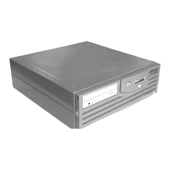
Product Information This chapter provides general product information about the HP B2600 workstation. This information is provided to help familiarize you with the main features and components of the workstation. - Page 12 Product Information Instructions in this chapter assume that you are running the Common Desktop Environment (CDE) on the HP-UX 10.20, 11.0 or 11i operating system with the latest additional core enhancements (ACE). The topics included in this chapter are: • Hardware System Overview •...
-
Page 13: Hardware System Overview
Product Information Hardware System Overview Hardware System Overview To help you gain a better understanding of the HP B Class workstation, Table 1-1. provides the workstation’s hardware system features. Table 1-1. HP B2600 Hardware System Features Workstation Feature Description Processor A PA8600 microprocessor with an operating frequency of 500MHz. -
Page 14: Operating System Overview
Managing Systems and Workgroups to configure your kernel. If you have any questions about Instant Ignition, refer to the document Using Your HP Workstation for more information. Note that both of the documents mentioned in the previous paragraphs can be found on the world-wide web at the following Uniform Resource Locator (URL): http://www.docs.hp.com/... -
Page 15: Your Workstation's Front Panel
16-character lines. The LCD displays messages about the state of the system, including chassis codes. The symbols in Figure 1-2. appear in the LCD if you have the HP-UX 10.20, 11.0 or 11i operating system booted on your system. They represent the different system activities shown: Figure 1-2. -
Page 16: Your Workstation's Rear Panel Connectors
Product Information Your Workstation’s Rear Panel Connectors Your Workstation’s Rear Panel Connectors This section describes the following connectors on the system unit’s rear panel: • Serial Ports 1 and 2 Connectors • USB Connectors • Power Cord Connector • Parallel Connector •... -
Page 17: Serial Ports 1 And 2 Connectors
USB Connectors The two Universal Serial Bus (USB) connectors support only the HP keyboard, mouse and hub (D6804A). You can connect the HP keyboard, mouse and hub in either of the USB connectors. The mouse and keyboard were shipped with your system unit, and the HP hub can be ordered separately. -
Page 18: Power Cord Connector
Audio Connectors (optional) Your workstation does not provide for audio input and output capabilities. If you require these capabilities, please contact your local HP Sales Representative. If you decide to purchase the recommended optional audio card, read the chapter “Remove/Install System Components”... -
Page 19: Monitors
Product Information Monitors Monitors The HP VISUALIZE fx5 and fxe2 graphics cards support any VESA monitors that are capable of a minimum XGA resolution of 1600 1200. Before using your monitor, you should become familiar with its controls, connectors and indicators. -
Page 20: Workstation Conversion Process
To convert your rack-mount system to a desktop system, you will need to order the desktop kit (HP Part Number: A7227A) from your local HP Sales Representative. You can find the conversion instructions in the chapter “Remove/Install System Components” in this manual. -
Page 21: Workstation Characteristics
Product Information Workstation Characteristics Workstation Characteristics Table 1-2. Workstation Characteristics Characteristic Description Weight Rack System (excl. keyboard and display) 14.1 kg (31.0 lb.) Weight Desk-side System (excl. keyboard and display) 15.9 kg (35.0 lb.) Dimensions Rack System Depth: 45.77 cm (18.02 inches) Width: 42.50 cm (16.73 inches) Height: 12.70 cm (5.00 inches) Dimensions Desk-side System... -
Page 22: Internal Components
Microprocessor The B2600 has one PA-8600 microprocessor with an operating frequency of 500 MHz. This processor has a 0.5 MB instruction cache and a 1.0 MB data cache. The microprocessor is cooled by a “turbocooler” which consists of a cylindrical heat sink and an integrated fan. - Page 23 5.8 lbs. (2.6 kg.) and the DC power supply weighs approximately 4.2 lbs. (1.9 kg.). CAUTION HP does not recommend and does not support the use of “ferro-active” or “ferro-resonant” power correction in conjunction with the B2600 workstation. This type of line conditioner represents an older technology that is not compatible with the most recent designs in active Power Factor Correction (PFC) power supplies such as those in the HP B2600 workstations.
- Page 24 Product Information Internal Components Chapter 1...
-
Page 25: Troubleshooting
Troubleshooting This chapter provides information about isolating a failing component, known as a Field Replaceable Unit (FRU), in HP B2600 workstations. -
Page 26: Chapter Overview
• Running ODE-Based Diagnostics Introduction to Troubleshooting To troubleshoot HP B2600 workstations, you must be familiar with the HP-UX operating system and be able to start and stop processes. You should also be familiar with the boot ROM diagnostics, ISL diagnostics, and the Support Tools Manager online tests, which are described in this chapter. - Page 27 Troubleshooting Flowcharts for Troubleshooting Figure 2-1. Main Flowchart for Troubleshooting Chapter 2...
- Page 28 Troubleshooting Flowcharts for Troubleshooting Figure 2-2. Console Troubleshooting Flowchart Chapter 2...
- Page 29 Troubleshooting Flowcharts for Troubleshooting Figure 2-3. Bootable Device Troubleshooting Flowchart Chapter 2...
- Page 30 Troubleshooting Flowcharts for Troubleshooting Figure 2-4. HP-UX Troubleshooting Flowchart Chapter 2...
-
Page 31: Identifying Lcd-Indicated Conditions
Chassis codes are the key to debugging selftest errors. If a failure is found during selftest, chassis codes are displayed in the system LCD. To debug a failure: 1. In Table C-1 of the “HP B2600 Chassis Codes” appendix, find the chassis code listed on the LCD. -
Page 32: Memory Failures
This feature allows the workstation to provide information to the operating system about memory failures. HP-UX uses this information to map out failing memory areas and continue normal operation. You can check the Memory Page Deallocation Table (PDT) using the pdt command in the Service menu of the Boot Console Handler (refer to Chapter 4). -
Page 33: Running System Verification Tests
Troubleshooting Running System Verification Tests Running System Verification Tests HP-UX uses an online diagnostics product called the Support Tools Manager that allows system operation verification. Three interfaces are available with the Support Tools Manager: a command line interface (accessed through the cstm command), a menu-driven interface (accessed through the mstm command), and the graphical user interface (accessed through the xstm command). -
Page 34: Running Ode-Based Diagnostics
Troubleshooting Running ODE-Based Diagnostics Running ODE-Based Diagnostics The Offline Diagnostic Environment (ODE) consists of diagnostic modules for testing and verifying system operation. ODE provides all the necessary functions for the user to load specified tests and interact with those tests. ODE is an ISL utility. -
Page 35: Remove/Replace System Components
Remove/Replace System Components This chapter discusses the removal and replacement of system components for the HP B2600 workstations. -
Page 36: Chapter Overview
To maintain FCC/EMI compliance, verify that all covers are replaced and that all screws are properly seated. Workstation Configurations Refer to the HP Workstations web site for a complete list of supported accessories, peripherals, and operating system versions for the HP B2600 workstations. The URL for the web site is: http://www.hp.com/workstations... -
Page 37: Tools Required
Remove/Replace System Components Tools Required Tools Required Use the following tools to remove or replace system upgrades (for example, hard disk drives): • Light-duty flat blade screwdriver with 6-inch (150 mm) blade • Number 2 Phillips screwdriver with 6-inch (150mm) blade •... -
Page 38: Removing/Replacing System Components
If you need to install a new system component, simply follow the procedures for replacing the particular component in this chapter. Electrostatic Discharge (ESD) Precautions To prevent damage to the HP B2600 workstation, observe all of the following ESD precautions while performing the system upgrade procedures: • Work on a static-free mat. -
Page 39: Prerequisite For Using The Procedures In This Chapter
Remove/Replace System Components Removing/Replacing System Components Prerequisite for Using the Procedures in this Chapter You must complete the following steps before performing any of the removal/replacement procedures in this chapter: 1. Power off the workstation (either by executing shutdown -h as root, or by simply pressing the power switch on the front panel of the workstation, which accomplishes the same thing), as well as the monitor and any attached peripheral devices. -
Page 40: Removing The Front Bezel And Top Cover
Removing the Front Bezel and Top Cover 1. Turn your workstation off and unplug it. 2. Lay your workstation on a soft anti-static surface with the HP logo text in the upright position. 3. Press in on both release buttons found on the ends of the bezel and pull outward from the workstation to remove it. -
Page 41: Replacing The Front Bezel And Top Cover
Removing/Replacing System Components Replacing the Front Bezel and Top Cover This section describes how to replace the HP B2600 workstation’s front bezel and top cover. After you have completed the necessary component upgrades to your workstation, you need to replace the top cover and bezel on you workstation. -
Page 42: Removing Memory Dimms
Remove/Replace System Components Removing/Replacing System Components Removing Memory DIMMs This section explains how to remove DIMM cards from your workstation. Please refer to the subsequent “Memory Configuration” section for the proper sequencing of DIMM cards in the system board’s memory slots. Here is the procedure for removing DIMM cards from your workstation: 1. - Page 43 Removing/Replacing System Components Memory Configuration The HP B2600 workstation has four memory slots, labeled SL0, SL1, SL2and SL3 (SL0 is the slot closest to the workstation’s chassis). You can mix 256MB, 512MB and 1GB memory cards in the memory slots, but you must install them using the memory sequence shown in Figure 3-5.
-
Page 44: Replacing Memory Dimms
2. Determine the appropriate memory slot(s) for your DIMM card(s). See Figure 3-6. You can mix 256MB, 512MB and 1GB memory cards in the memory slots, but you must install them using the memory sequence shown in Figure 3-6. Figure 3-6. Memory Loading Sequence in the HP B2600 Chapter 3... - Page 45 Memory tab. The next window that appears will tell you how much memory you have available. If the amount of memory you were expecting does not appear, repeat this procedure. If the correct amount of memory still does not appear, contact your local HP Support Representative.
-
Page 46: Removing The Cd Drive
Remove/Replace System Components Removing/Replacing System Components Removing the CD Drive To remove the CD drive, follow this procedure: 1. Complete the procedure in the section “Removing the Front Bezel and Top Cover” found in this chapter. 2. Disconnect the CD drive control cable by pulling up on its pull tab and disconnect the power cable by pressing in on its latch release. - Page 47 Remove/Replace System Components Removing/Replacing System Components 4. Press in on the retainer clips on both sides of the CD drive bay and pull toward you. See Figure 3-10. Figure 3-10. Removing the CD Drive Bay and CD Drive CD Drive CD Drive Retainer Clip CD Drive...
- Page 48 Remove/Replace System Components Removing/Replacing System Components 6. Disconnect the CD drive power cable, control cable, and audio cable (if an audio card is present). See Figure 3-12. Note that these cables are keyed for easy replacement. Figure 3-12. Disconnecting the CD Drive’s Cables Power Cable Control Cable Audio Cable...
- Page 49 Remove/Replace System Components Removing/Replacing System Components 8. Slide the CD drive out of the CD drive bay. See Figure 3-14. Figure 3-14. CD Drive Removed from the CD Drive Bay Mounting Screw Holes CD Drive CD Drive Mounting Screw Holes Chapter 3...
-
Page 50: Replacing The Cd Drive
Remove/Replace System Components Removing/Replacing System Components Replacing the CD Drive To replace the CD drive, follow this procedure: 1. Remove the current CD drive if you have not already done this. Otherwise, skip this step. To remove the CD drive, follow the procedure in the section “Removing the CD Drive”... - Page 51 Remove/Replace System Components Removing/Replacing System Components 4. Connect the CD drive power cable, control cable, and audio cable (if an audio card is present). See Figure 3-17. Note that these cables are keyed for easy replacement. Figure 3-17. Connecting the CD Drive’s Cables Power Cable Control Cable Audio Cable...
- Page 52 Remove/Replace System Components Removing/Replacing System Components 6. Slide the CD drive bay and CD drive back into the workstation. You will hear the retainer clips snap in place when the CD drive bay and CD drive are properly installed. See Figure 3-19. Figure 3-19.
- Page 53 Disk Devices icon. In the next window that appears, you should see your CD drive listed. If it is not listed, repeat this procedure. If your CD drive is still not listed, contact your local HP Support Representative. Chapter 3...
-
Page 54: Removing The Pci Cage, I/O Card And Pci Backplane Board
Remove/Replace System Components Removing/Replacing System Components Removing the PCI Cage, I/O Card and PCI Backplane Board To remove the PCI cage, I/O card and PCI backplane board from the system, you will need to follow the procedures discussed in the subsequent sections. PCI Cage Removal To remove the PCI cage, follow this procedure: 1. - Page 55 Remove/Replace System Components Removing/Replacing System Components I/O Card Removal This procedure assumes you have removed the PCI cage from the system. 1. Set the PCI cage on an anti-static surface and remove the PCI cage cover. See Figure 3-24. Figure 3-24. Removing the PCI Cage Cover PCI Cage Cover 2.
- Page 56 Remove/Replace System Components Removing/Replacing System Components 3. Grasp the I/O card’s bulkhead and the rear edge and lift it out of its PCI slot. As you lift up on the I/O card, you may need to slightly rock it back and forth. This will loosen the I/O card from its PCI slot.
- Page 57 Remove/Replace System Components Removing/Replacing System Components 2. Slide the PCI backplane board away from the PCI cage’s I/O card openings and remove it from the PCI cage. See Figure 3-28. Note that the PCI backplane board has two elongated slots cut in it that allow the card to slide in grooves located on the top of two PCI cage standoffs.
- Page 58 Remove/Replace System Components Removing/Replacing System Components PCI Card Guide Removal The PCI cover’s card guides are made of plastic and can be easily removed to accommodate PCI cards that have components or connectors with which the guide interferes. Therefore, you may need to remove them from the PCI cover. To do this follow the procedure in this section.
-
Page 59: Replacing The Pci Cage, I/O Card And Pci Backplane Board
Remove/Replace System Components Removing/Replacing System Components Replacing the PCI Cage, I/O Card and PCI Backplane Board To replace the PCI backplane board, I/O card and PCI cage in the system, you will need to follow the procedures discussed in the subsequent sections. PCI Backplane Board Replacement To replace the PCI backplane board, follow this procedure: 1. - Page 60 Remove/Replace System Components Removing/Replacing System Components I/O Card Replacement This procedure assumes you have replaced the PCI cage backplane board in the system. 1. Replace the PCI backplane board in the PCI cage if you have not already done this. Otherwise, skip this step.
- Page 61 Remove/Replace System Components Removing/Replacing System Components 5. Replace the PCI cage cover by inserting its two retainer tabs into the retainer slots and rotating the cover downward until the cover’s slide lock snaps into place in the PCI cage’s slide lock slot. See Figure 3-35. Figure 3-35.
- Page 62 In the next window that appears, you should see your I/O card listed. If it is not listed, repeat the previous procedures in this section including this one. If your I/O card is still not listed, contact your local HP Support Representative. PCI Card Guide Replacement This section explains how to replace a PCI card guide that has been removed from your PCI cage cover.
-
Page 63: Removing The Hard Disk Drive(S)
Remove/Replace System Components Removing/Replacing System Components Removing the Hard Disk Drive(s) To remove the hard disk drive(s), follow this procedure: 1. Complete the procedure in the section “Removing the CD Drive” (steps 1 through 3; in this chapter), “Removing the DAT Drive” (steps 1 through 5; in Appendix F), or “Removing the Flexible Disk Drive”... -
Page 64: Replacing The Hard Disk Drive(S)
Remove/Replace System Components Removing/Replacing System Components Replacing the Hard Disk Drive(s) To replace the hard disk drive(s), follow this procedure: 1. Remove the CD drive, DAT drive or flexible disk drive if you have not already done this. Otherwise, skip this step. To remove the CD drive, DAT drive or flexible disk drive, follow the procedure in the section “Removing the CD Drive”... - Page 65 Disk Devices icon. In the next window that appears, you should see your hard disk drive listed. If it is not listed, repeat this procedure. If your hard disk drive is still not listed, contact your local HP Support Representative. Chapter 3...
-
Page 66: Removing The Liquid Crystal Display (Lcd) Module
Remove/Replace System Components Removing/Replacing System Components Removing the Liquid Crystal Display (LCD) Module To remove the liquid crystal display, follow this procedure: 1. Complete the procedure in the section “Removing the Front Bezel and Top Cover” found in this chapter. 2. -
Page 67: Replacing The Liquid Crystal Display (Lcd) Module
LCD does not light up and the heart shaped activity indicator is not blinking, repeat this procedure. If your LCD continues to not light up and the heart shaped activity indicator is not blinking, contact your local HP Support Representative. Chapter 3... -
Page 68: Removing The Ac Or Dc Power Supply
Removing the AC or DC Power Supply The HP B2600 workstation can be purchased with either an AC or DC power source. This section covers how to remove the AC power supply. To learn how to remove the DC power supply, see Appendix E in this document. - Page 69 Remove/Replace System Components Removing/Replacing System Components 4. Unscrew the four power supply mounting screws located on the back of the system. See Figure 3-48. Note that there is a power supply support arm that fits into a slot on the system divider panel.
-
Page 70: Replacing The Ac Or Dc Power Supply
Removing/Replacing System Components Replacing the AC or DC Power Supply You can choose to have either an AC or DC power source when ordering a HP B2600 workstation. The AC power source is suitable for most of your computing needs. - Page 71 If your workstation’s LCD does not light up and the CDE login screen does not appear, repeat this procedure. If your workstation’s LCD still does not light up and the CDE login screen does not appear, contact your local HP Support Representative.
-
Page 72: Removing The System Board
Remove/Replace System Components Removing/Replacing System Components Removing the System Board To remove the system board, follow this procedure: 1. Complete the procedure in the section “Removing the CD Drive” (steps 1 through 3; in this chapter), “Removing the DAT Drive” (steps 1 through 5; in Appendix F), or “Removing the Flexible Disk Drive”... - Page 73 Remove/Replace System Components Removing/Replacing System Components 7. Grasp the system board by the microprocessor’s turbo-cooler heatsink and the handle located on the back edge of the system board, and slide the system board toward the front of the workstation (in the direction of the arrow). See Figure 3-55. Note that this step unlocks the system board from its standoffs.
-
Page 74: Replacing The System Board
Remove/Replace System Components Removing/Replacing System Components Replacing the System Board To replace the system board, follow this procedure: 1. Remove the system board if you have not already done this. Otherwise, skip this step. To remove the system board, follow the procedure in the section “Removing the System Board”... - Page 75 Remove/Replace System Components Removing/Replacing System Components 4. Align the system board screw hole that is located on the workstation’s chassis with the threaded screw hole on the system board’s handle and screw in the system board’s rear mounting screw. See Figure 3-59. Figure 3-59.
- Page 76 If your workstation’s LCD does not light up and the CDE login screen does not appear, repeat this procedure. If your workstation’s LCD still does not light up and the CDE login screen does not appear, contact your local HP Support Representative. Chapter 3...
-
Page 77: Removing The Fan Modules
Removing/Replacing System Components Removing the Fan Modules The HP B2600 workstation has two fan modules to keep it cool. There is a fan module located in the system area and one in the PCI area. See Figure 3-61. This section explains how to remove these fan modules. - Page 78 Remove/Replace System Components Removing/Replacing System Components System Area Fan Module Removal To remove the fan module from the system area, follow this procedure: 1. Complete the procedure in the section “Removing the Front Bezel and Top Cover” found in this chapter. 2.
- Page 79 Remove/Replace System Components Removing/Replacing System Components 5. Remove the fan-module mounting screw. See Figure 3-64. Figure 3-64. Removing the Fan-Module Mounting Screw Fan Module Mounting Screw 6. Remove the fan module from the workstation by tilting it back away from the workstation chassis and lifting it out of the three fan-module slots on the front part of the workstation’s chassis.
- Page 80 Remove/Replace System Components Removing/Replacing System Components PCI Area Fan Module Removal To remove the fan module in the PCI area, follow this procedure: 1. Complete the procedure in the section “Removing the Front Bezel and Top Cover” found in this chapter. 2.
- Page 81 Remove/Replace System Components Removing/Replacing System Components 5. Remove the fan module from the workstation by tilting it back away from the workstation chassis and lifting it out of the three fan-module slots on the front part of the workstation chassis. See Figure 3-68. Figure 3-68.
-
Page 82: Replacing The Fan Modules
Removing/Replacing System Components Replacing the Fan Modules The HP B2600 workstation has two fan modules to keep it cool. There is a fan module located in the system area and one in the PCI area. See Figure 3-69. This section explains how to replace these fan modules. - Page 83 Remove/Replace System Components Removing/Replacing System Components System Area Fan Module Replacement To replace the fan module in the system area, follow this procedure: 1. Remove the system area fan module if you have not done this. Otherwise, skip this step. To remove the system area fan module, follow the procedure in the section “System Area Fan Module Removal”...
- Page 84 9. Determine that your system area fan-module replacement was successful by checking the workstation’s LCD for fan error messages. If LCD fan error messages appear, repeat this procedure. If your LCD still displays fan error messages, contact your local HP Support Representative.
- Page 85 Remove/Replace System Components Removing/Replacing System Components PCI Area Fan Module Replacement To replace the fan module from the PCI area, follow this procedure: 1. Remove the PCI area fan module if you have not done this. Otherwise, skip this step. To remove the PCI area fan module, follow the procedure in the section “PCI Area Fan Module Removal”...
- Page 86 8. Determine that your PCI area fan-module replacement was successful by checking the workstation’s LCD for fan error messages. If LCD fan error messages appear, repeat this procedure. If your LCD still displays fan error messages, contact your local HP Support Representative.
-
Page 87: Removing The Audio Card
Remove/Replace System Components Removing/Replacing System Components Removing the Audio Card If you originally installed the audio card and need to remove it, follow the procedure in this section. NOTE The audio card was originally installed in slot one of the system. This is the recommended PCI card slot to use if you are going to replace this card with a new one. - Page 88 Remove/Replace System Components Removing/Replacing System Components 4. Remove the PCI cage cover and disconnect the audio-extender cable from the audio card if you have an audio cable. See Figure 3-78. Note that the audio-extender cable’s connector can be remove from the audio card by press in on the connector’s latch release and pulling outward on the cable.
-
Page 89: Replacing The Audio Card
Remove/Replace System Components Removing/Replacing System Components Replacing the Audio Card To replace the audio card, follow this procedure: NOTE PCI slot one is the recommended PCI card slot to use when installing the audio card. To determine the correct numbering for the PCI card slots, see the PCI card slot openings on the back of the workstation. - Page 90 Remove/Replace System Components Removing/Replacing System Components 4. Secure the audio card in slot 1 by screwing the audio-card bulkhead screw into the PCI cage. See Figure 3-83. Figure 3-83. Secure the Audio Card in Slot 1 Audio Card Bulkhead Screw PCI Card Slots 5.
- Page 91 Remove/Replace System Components Removing/Replacing System Components 6. Insert the PCI cage into the workstation. See Figure 3-85. Figure 3-85. Insert the PCI Cage into the Workstation Audio-Cable Extender PCI Cage 7. Connect the audio cable (supplied with the audio card) to the CD drive. See Figure 3-86. Figure 3-86.
- Page 92 “Replacing the Front Bezel and Top Cover” found in this chapter. 11.Determine that your audio card replacement was successful. To do this read the section “Using Your Audio Card (Optional)” in Chapter 1 of the Getting Started Guide for the HP B2600 workstation. Chapter 3...
-
Page 93: Converting Your System For Desktop Or Rack-Mount Use
Converting Your System for Desktop or Rack-Mount Use The HP B2600 workstation can be used as a desktop or a rack-mount system. This section covers how to convert your system from a desktop system to a rack-mount system and from a rack-mount system to a desktop system. - Page 94 Remove/Replace System Components Converting Your System for Desktop or Rack-Mount Use These seven cover locks hold the top and bottom covers to the system chassis. See Figure 3-91. Figure 3-91. Plastic Cover Locks and their Slots on the System Chassis Plastic Cover System...
- Page 95 Remove/Replace System Components Converting Your System for Desktop or Rack-Mount Use place. See Figure 3-93. Note that before the bezel and its end caps are placed on the system, the system must be installed in the rack as described in the rack installation instructions provided with your rack-mount kit.
-
Page 96: Converting Your Rack-Mount System To A Desktop System
Converting Your Rack-Mount System to a Desktop System To convert your rack-mount system to a desktop system, you will need to order the desktop kit (HP Part Number A7227A) from you local HP Sales Representative. Next, follow this procedure: 1. Unplug the workstation and reverse the procedure in the section “Converting Your Desktop System to a Rack-Mount System”... -
Page 97: Boot Console Handler
Boot Console Handler This chapter explains how to use the Boot Console Handler, which provides an interactive environment after the power-on sequence in HP B2600 workstations. -
Page 98: Chapter Overview
Boot Console Handler Chapter Overview Chapter Overview This chapter contains the following main sections: • Boot Console Handler Features • Accessing the Boot Console Handler • Boot Console Menus • Booting the Workstation • Searching for Bootable Media • Resetting the Workstation •... -
Page 99: Boot Console Handler Features
Boot Console Handler Features Boot Console Handler Features There are times when you want to interact directly with the B2600 workstation before it boots the operating system. These workstations provide a menu-driven Boot Console Handler that allows you to perform special tasks, display information, and set certain system parameters, even if the operating system is unavailable. -
Page 100: Accessing The Boot Console Handler
2. Press the power switch on the front panel of the workstation to power it off. NOTE There is no need to manually shut down the HP-UX operating system on the workstation before powering it off. When you press the power switch, the workstation automatically shuts down the operating system before terminating the power. -
Page 101: Boot Console Menus
Boot Console Handler Boot Console Menus Boot Console Menus The boot console menus follow, showing the various tasks you can perform and the available information. The shortened version of each command is indicated by the uppercase letters. Help is available for all the menus and commands by using either help, he, or ? and the menu or command for which you want help. - Page 102 Boot Console Handler Boot Console Menus ------ Configuration Menu ----------------------------- Command Description ------- ----------- AUto [BOot|SEArch|STart][ON|OFF]Display or set specified flag BootID [<proc> [<boot ID>]] Display or modify processor boot ID BootINfo Display boot-related information CPUconfig [<proc>[ON|OFF]] Config/deconfig processor DEfault Set the system to predefined values FanChoice [DeskSide|RackMount] Display or set the fan preference FastBoot [ON|OFF]...
- Page 103 Boot Console Handler Boot Console Menus ------ Information Menu ------------------------------- Command Description ------- ----------- Display all system information BootINfo Display boot-related information CAche Display cache information ChipRevisions Display revisions of VLSI and firmware COprocessor Display coprocessor information FwrVersion Display firmware version Display I/O interface information LanAddress Display built-in system LAN address...
- Page 104 Boot Console Handler Boot Console Menus ------ Service Menu ----------------------------------- Command Description ------- ----------- ChassisCodes [<proc>|ON|OFF] Display/enable/disable chassis codes CLEARPIM Clear (zero) the contents of PIM EepromRead [<addr> [<len>]] Read EEPROM locations MemRead <addr>[<len>] [<type>] Read memory locations PciDelay [<value>] Display or set PCI delay value PDT [CLEAR] Display or clear the Page...
-
Page 105: Booting The Workstation
Booting the Workstation Booting the Workstation You usually start a workstation by turning it on and waiting for HP-UX to boot automatically. However, you may not always want the usual boot sequence to occur. For example, you may want to start the workstation from an operating system that is stored on a device that is different from the usual boot device. - Page 106 ISL is the program that actually controls the loading of the operating system. By interacting with ISL, you can choose to load an alternate version of the HP-UX operating system. If you do not want to interact with ISL, you must enter no (N).
-
Page 107: Searching For Bootable Media
Boot Console Handler Searching for Bootable Media Searching for Bootable Media To list all devices that contain bootable media, follow the directions in the section “Accessing the Boot Console Handler” found in this chapter, and type the following at the prompt: Main Menu: Enter command >... -
Page 108: Resetting The Workstation
Boot Console Handler Resetting the Workstation Resetting the Workstation To reset the workstation to its predefined values, follow the directions in the section “Accessing the Boot Console Handler” found in this chapter, and type the following at the prompt to access the Configuration Menu: Main Menu: Enter command >... -
Page 109: Displaying And Setting Paths
Boot Console Handler Displaying and Setting Paths Displaying and Setting Paths A path is the hardware address of a device that is attached to the I/O system of a workstation. The path command sets the system paths shown in Table 4-1. The path command sets and displays the hardware address of a specified device attached to the I/O bus of the workstation. - Page 110 Boot Console Handler Displaying and Setting Paths To set a system path to a new value, follow the directions in the section “Accessing the Boot Console Handler” found in this chapter, and type the following at the prompt: Main Menu: Enter command > path path_type path [Enter] where path_type is one of the path types listed in Table 4-1.
-
Page 111: Displaying And Setting The Monitor Type
Boot Console Handler Displaying and Setting the Monitor Type Displaying and Setting the Monitor Type The workstation ships from the factory preset to use a monitor with a specific resolution and frequency. If the workstation’s monitor is replaced with a different type of monitor, you may have to reconfigure the workstation to support the new monitor. -
Page 112: Displaying The Current Monitor Configuration
Boot Console Handler Displaying and Setting the Monitor Type Displaying the Current Monitor Configuration To display the current monitor configuration for the workstation from the Configuration Menu of the Boot Console Handler, follow the directions in the section “Accessing the Boot Console Handler”... - Page 113 Boot Console Handler Displaying and Setting the Monitor Type MONITOR INFORMATION Path Slot Head Type Size Freq Class ---- ---- ---- ---- --------- ---- ----- GRAPHICS(1) 1280x1024 75Hz PCI GRAPHICS(1) 1280x1024 75Hz PCI, Double buffered GRAPHICS(1) 1280x1024 75Hz PCI, Greyscale GRAPHICS(1) 1280x1024 75Hz PCI, Double buffered, Greyscale GRAPHICS(1)
-
Page 114: Setting The Monitor Type At Power On
Boot Console Handler Displaying and Setting the Monitor Type Setting the Monitor Type at Power On If you replace a workstation’s monitor with a different monitor type, and do not set the workstation’s graphics parameters by using the monitor command before doing so, you may need to perform the following if your screen is blank. -
Page 115: Troubleshooting Monitor Problems
4. Power on the workstation. The system will now display the console to the terminal connected to Serial 1 port. Note that you can use a 9-pin to 9-pin serial cable (HP Part Number F1044-80002) to connect an HP OmniBook serial port to the workstation. -
Page 116: Displaying The Current Memory Configuration
Boot Console Handler Displaying the Current Memory Configuration Displaying the Current Memory Configuration The following sample screen output uses the memory command to show a memory configuration table with properly-installed and configured memory. To display the current memory configuration for a workstation, first follow the directions in the section “Accessing the Boot Console Handler”... -
Page 117: Displaying The Status Of The I/O Slots
Boot Console Handler Displaying the Status of the I/O Slots Displaying the Status of the I/O Slots The IO command lets you identify all built-in I/O devices and optional I/O devices installed in the option slots. It is available in the Information Menu. To use the IO command from the Information Menu of the Boot Console Handler, type the following: Information Menu: Enter command >... -
Page 118: Setting The Auto Boot And Auto Search Flags
Boot Console Handler Setting the Auto Boot and Auto Search Flags Setting the Auto Boot and Auto Search Flags The auto boot and auto search flags are variables stored in the system’s non-volatile memory. (Non-volatile memory retains its contents even after power is turned off.) If you reset these flags to new values, the change takes effect the next time you reboot the workstation. -
Page 119: Displaying And Setting The Security Mode
Boot Console Handler Displaying and Setting the Security Mode Displaying and Setting the Security Mode The secure flag is a variable stored in non-volatile memory. (Non-volatile memory retains its contents even after power is turned off.) If you reset this flag to a new value, the change takes effect the next time you reboot the workstation. -
Page 120: Displaying And Setting Fastboot Mode
Boot Console Handler Displaying and Setting Fastboot Mode Displaying and Setting Fastboot Mode When fastboot is enabled (set to on), the workstation does a quick check of the memory and skips some processor selftests during its power-on selftests. This enables the workstation to complete its boot process quicker. -
Page 121: Displaying The Lan Station Address
Boot Console Handler Displaying the LAN Station Address Displaying the LAN Station Address It is sometimes necessary to supply the LAN station address of the workstation to other users. For example, if the workstation is to become a member of a cluster, the cluster administrator needs to know the LAN station address in order to add the workstation to the cluster. -
Page 122: Displaying System Information
Boot Console Handler Displaying System Information Displaying System Information The all command allows you to display the system’s processor revision and speed, cache size, memory size, flag settings, and the boot and console paths. To display system information, from the Information Menu type the following: Information Menu: Enter command >... -
Page 123: Using Remote Power-On
Using Remote Power-On Using Remote Power-On The B2600 workstation has a remote power-on feature that allows you to power up and shut down your workstation remotely through the Serial 1 port. The RS232 receive line is monitored by the system board Remote Power Controller (RPC). This controller responds... -
Page 124: Troubleshooting Hint For An Unresponsive Rpc
Boot Console Handler Using Remote Power-On 2. Press any key. You will then see the message: Boot terminated The Main Menu of the boot console appears. 3. At the Main Menu prompt, type the following and press Enter Main Menu: Enter command > service 4. -
Page 125: Setting The Fan Speed
Setting the Fan Speed Setting the Fan Speed There are two fan speed settings available on the B2600 workstation. The RackMount fan speed is used for B2600s that are installed in a rack. The DeskSide fan speed is used for B2600s that are used as desktop systems. - Page 126 Boot Console Handler Setting the Fan Speed 3. Enter the following command at the Configuration Menu prompt: Configuration Menu: Enter command > FanChoice DeskSide 4. Return to the Main Menu and enter this command at the prompt to continue booting: Main Menu: Enter command >...
-
Page 127: Initial System Loader (Isl) Environment
ISL> ISL is the program that actually controls the loading of the operating system. By interacting with ISL, you can choose to load an alternate version of the HP-UX operating system. For example, if the usual kernel (/stand/vmunix) on the root disk has become corrupted, and you wish to boot the workstation from the backup kernel (/stand/vmunix.prev), type the following at the ISL>... -
Page 128: Isl User Commands
The entry for the keyboard and mouse devices begins at byte address 160 and ends at 191. • listautofl or lsautofl - lists the contents of the (HP-UX) autoboot file. • support - boots the Support Tape from the boot device. -
Page 129: Block Diagram
Block Diagram This chapter contains the block diagram for the B2600 workstation’s system board and PCI board. -
Page 130: System Board And Pci Board
System Board and PCI Board System Board and PCI Board The B2600 system is designed around a PA8600 processor and a Memory and I/O Controller. This system is segmented into a system board and a PCI backplane board (the area designated in the dotted lines). See Figure 5-1. -
Page 131: System Board
PCI 1x or PCI 2x bus and it can convert two data lines to a PCI 4x bus. The B2600 uses two data lines and two PCI bridges in its I/O subsystem. - Page 132 Block Diagram System Board and PCI Board System Management Component The System Management chip includes the following functions and internal hardware: Functions • Hardware semaphore support • Software reset control • Serial Presence Detect (SPD) bus • Fan control • Power switch monitoring •...
-
Page 133: Pci Back-Plane Board
1x capable slots. The other two slots are 5V, 64-bit, 33MHz, PCI 2x capable slots. The two 32-bit slots will support half-length PCI cards. The two 64-bit slots will support full-length PCI cards. The physical configuration for the add-in slots in the B2600 is shown in Figure 5-2. - Page 134 Block Diagram System Board and PCI Board Chapter 5...
-
Page 135: Regulatory Statements
Regulatory Statements This Appendix contains electromagnetic compatibility information and optical and acoustical statements. -
Page 136: Declaration Of Conformity
Regulatory Statements Declaration of Conformity according to ISO/IEC Guide 22 and EN 45014 Appendix A... -
Page 137: Electromagnetic Compatibility
Regulatory Statements Electromagnetic Compatibility Electromagnetic Compatibility Federal Communications Commission (FCC) This equipment has been tested and found to comply with the limits for a Class A digital device, pursuant to Part 15 of the FCC Rules and the Canadian Department of Communications. -
Page 138: Vcci Statement For Class A Products
Regulatory Statements Electromagnetic Compatibility VCCI Statement for Class A Products Korea RRL Statement for Class A Product Taiwan Class A Warning Appendix A... -
Page 139: Optical And Acoustical Statements
Regulatory Statements Optical and Acoustical Statements Optical and Acoustical Statements Visible LED Statement The LEDs on this product are classified as “Class 1 LED Product” in accordance with EN 60825-1. Laser Safety Statement for a Class 1 Laser Product The CD-ROM mass-storage system is certified as a Class 1 laser product under the U.S. Department of Health and Human Services (DHHS) Radiation Performance Standard according to the Radiation Control for Health and Safety Act of 1968. - Page 140 Regulatory Statements Optical and Acoustical Statements Appendix A...
-
Page 141: Specifications
Specifications This appendix lists the environmental and electrical specifications for the HP B2600 workstations. -
Page 142: Environmental Specifications
Specifications Environmental Specifications Environmental Specifications Altitude Operating: 0–10,000 ft (0–3,000 m) @ +5˚C to +35˚ C Non-operating: 15,000 ft (0–4,500 m) @ –40 to +70˚ C DC Magnetic Field Interference Operating: <1 Gauss at surface of product Non-operating: <2 milli Gauss @ 7 feet Electromagnetic Interference (EMI) Emissions: FCC Class A CISPR A... -
Page 143: Shock
Specifications Electrical Specifications Shock Operating: 20g at 3ms, 1/2 sine in normal axis with no hard errors Non-operating: 80g at 3ms, 1/2 sine, all six faces Vibration Operating random: 0.21 Grms, 5–500 Hz Swept sine survival: 0.5 g peak, 5–500 Hz Random survival: 2.09 Grms, 5–500 Hz Electrical Specifications... - Page 144 Specifications Electrical Specifications Appendix B...
-
Page 145: Hp B2600 Chassis Codes
HP B2600 Chassis Codes This appendix lists the LCD chassis codes for the HP B2600 workstation. -
Page 146: Chassis Codes
HP B2600 Chassis Codes Chassis Codes Chassis Codes Table C-1.lists all of the chassis codes for the B2600 workstations. Table C-1. Chassis Codes for B2600 Workstations Ostat Code Message Description CPU n detected an unexpected HPMC. 1n01 SYS BD HPMC occurred... - Page 147 HP B2600 Chassis Codes Chassis Codes Table C-1. Chassis Codes for B2600 Workstations Ostat Code Message Description CPU n detected an unexpected data 1n12 SYS BD data mem prot tr memory protection trap. CPU n detected an unexpected data 1n13...
- Page 148 HP B2600 Chassis Codes Chassis Codes Table C-1. Chassis Codes for B2600 Workstations Ostat Code Message Description CPU n is starting its external interrupt 1n26 SYS BD CPU n ext intrpt self-test. CPU n is starting its interval timer 1n27...
- Page 149 HP B2600 Chassis Codes Chassis Codes Table C-1. Chassis Codes for B2600 Workstations Ostat Code Message Description CPU n is starting its TLB translation 1nB2 SYS BD CPU n TLB trans self-test. The monarch CPU failed. 1nBA SYS BD monarch CPU fail The CPU identifier was out of range.
- Page 150 HP B2600 Chassis Codes Chassis Codes Table C-1. Chassis Codes for B2600 Workstations Ostat Code Message Description CPU n is starting its data cache tag 2n80 SYS BD CPU n dcache tag self-test. CPU n is starting its data cache ECC...
- Page 151 HP B2600 Chassis Codes Chassis Codes Table C-1. Chassis Codes for B2600 Workstations Ostat Code Message Description CPU n invoke LDB CPU n is starting the low-level debugger. 3n07 SYS BD CPU n detected an unsupported system 3n09 SYS BD bad sys mde byte mode.
- Page 152 HP B2600 Chassis Codes Chassis Codes Table C-1. Chassis Codes for B2600 Workstations Ostat Code Message Description CPU n is bypassing its late self-tests to 4n01 SYS BD CPU n skip lst save time. CPU n finished its late self-tests.
- Page 153 HP B2600 Chassis Codes Chassis Codes Table C-1. Chassis Codes for B2600 Workstations Ostat Code Message Description CPU n is starting its data cache miss 4n60 SYS BD CPU n dcache miss self-test. CPU n detected an unknown error on the...
- Page 154 HP B2600 Chassis Codes Chassis Codes Table C-1. Chassis Codes for B2600 Workstations Ostat Code Message Description Try to find a single memory bank to use 7020 SYS BD search for IMM for the initial memory module. DIMM s was the initial memory module...
- Page 155 HP B2600 Chassis Codes Chassis Codes Table C-1. Chassis Codes for B2600 Workstations Ostat Code Message Description The DIMM table is full--cannot add new 7207 DIMM DIMM table full type. SPD didn’t find any memory DIMMs. 7208 DIMM no DIMMs found SPD is checking memory slot s.
- Page 156 HP B2600 Chassis Codes Chassis Codes Table C-1. Chassis Codes for B2600 Workstations Ostat Code Message Description Insufficient error-free memory to 7309 DIMM insufficient mem continue. Memory interleave generation failed. 730C SYS BD mem intrlv fail Main memory configuration complete.
- Page 157 HP B2600 Chassis Codes Chassis Codes Table C-1. Chassis Codes for B2600 Workstations Ostat Code Message Description Memory ECC test failed to detect 7611 DIMM ECC single data single-bit data error. Memory ECC test failed to detect 7612 DIMM ECC single ECC single-bit ECC error.
- Page 158 HP B2600 Chassis Codes Chassis Codes Table C-1. Chassis Codes for B2600 Workstations Ostat Code Message Description Printing memory controller status word to 7845 SYS BD mem ctlr stat wd RS-232. Multiple memory errors detected. 7846 SYS BD mem err overflow Memory address outside configured...
- Page 159 HP B2600 Chassis Codes Chassis Codes Table C-1. Chassis Codes for B2600 Workstations Ostat Code Message Description Cannot load IODC entry_io for boot 80F6 EXT IO boot read error device. Error detected during boot device I/O. 80F7 EXT IO boot IO error Invalid boot device class;...
- Page 160 HP B2600 Chassis Codes Chassis Codes Table C-1. Chassis Codes for B2600 Workstations Ostat Code Message Description Cannot re-establish communications with 8A04 EXT IO No USB keyboard the USB keyboard. Running PCI Built-In Self-Test 8C06 EXT IO PCI BIST test PCI Built-In Self-Test failed.
- Page 161 HP B2600 Chassis Codes Chassis Codes Table C-1. Chassis Codes for B2600 Workstations Ostat Code Message Description Serial port 1 failed to initialize as a 9C51 SYS BD bad init SERIAL1 console device. Console display is on serial port 2.
- Page 162 HP B2600 Chassis Codes Chassis Codes Table C-1. Chassis Codes for B2600 Workstations Ostat Code Message Description The monarch CPU is starting the late C3FF SYS BD late monarch tst (post-memory) monarch-only tests. The late (post-memory) monarch-only C3FF SYS BD late monarch flt tests failed.
- Page 163 HP B2600 Chassis Codes Chassis Codes Table C-1. Chassis Codes for B2600 Workstations Ostat Code Message Description Look for built-in graphics card. C680 SYS BD builtin graphics Look for graphics card in PCI slot s. C68s SYS BD test graph in s...
- Page 164 HP B2600 Chassis Codes Chassis Codes Table C-1. Chassis Codes for B2600 Workstations Ostat Code Message Description The operating system TOC handler is CB03 SYS BD bad OS TOC code invalid. Firmware will soft boot the system. The size of the operating system TOC...
- Page 165 HP B2600 Chassis Codes Chassis Codes Table C-1. Chassis Codes for B2600 Workstations Ostat Code Message Description A Transfer of Control caused entry to CB73 SYS BD TOC occurred PDCE_CHECK (the firmware trap handler). An error was detected on rope r.
- Page 166 HP B2600 Chassis Codes Chassis Codes Table C-1. Chassis Codes for B2600 Workstations Ostat Code Message Description PCI data parity error. I/O error log word 3 CBC2 SYS BD PCI data parity contains the error address. Multiple PCI data parity errors. I/O error...
- Page 167 HP B2600 Chassis Codes Chassis Codes Table C-1. Chassis Codes for B2600 Workstations Ostat Code Message Description A PCI device asserted SERR# multiple CBE2 SYS BD PCI SERR#; OV times. Unknown PCI error detected. CBE3 SYS BD Unknown PCI err...
- Page 168 HP B2600 Chassis Codes Chassis Codes Table C-1. Chassis Codes for B2600 Workstations Ostat Code Message Description A High-Priority Machine Check occurred CBFE SYS BD HPMC during TOC during Transfer of Control processing. A High-Priority Machine Check occurred CBFF SYS BD multiple HPMCs while processing another HPMC.
-
Page 169: Accessories And Replacement Parts
Accessories and Replacement Parts This appendix contains an overview of system accessories, an exploded view of the workstation components and a components parts list. Appendix D... -
Page 170: Hp B2600 Accessories
Accessories and Replacement Parts HP B2600 Accessories HP B2600 Accessories This section provides a list of supported accessories for the B2600 workstation. B2600 Supported Accessories Processor PA8600, 500MHz A6070A Memory Upgrades 256MB SDRAM DIMM card A4997A 512MB SDRAM DIMM card... -
Page 171: Parts And Part Numbers
Accessories and Replacement Parts Parts and Part Numbers Parts and Part Numbers This section provides an exploded view of the HP B2600 parts and a list of its part numbers. Figure D-1 Exploded View of the B2600 Parts Appendix D... - Page 172 Accessories and Replacement Parts Parts and Part Numbers Table D-1 HP 2600 Parts List Item Description Replacement Part Exchange Part Number Number System Board 500MHz PA8600 CPU Assembly A6070-699001 Hard Disk Drive 9GB, 10K RPM LVD disk A1658-69027 18GB, 10K RPM LVD disk...
- Page 173 Accessories and Replacement Parts Parts and Part Numbers Table D-1 HP 2600 Parts List Item Description Replacement Part Exchange Part Number Number Fans 92mm Fan/bracket assembly A6070-62033 60mm Fans/bracket assembly A6070-62034 Liquid Crystal Display LCD cable assembly A6070-63003 LCD bracket assembly...
- Page 174 Accessories and Replacement Parts Parts and Part Numbers Appendix D...
-
Page 175: Dc Power Supply
DC Power Supply This appendix explains how to remove and replace your DC power supply. Note that the DC power supply allows you to set up your computer so that it is always on and ready for use. Please keep in mind that this appendix should only be used by service-trained personnel that are familiar with hazards associated with connecting equipment to a centralized DC power source. -
Page 176: Dc Power Supply Considerations
DC Power Supply DC Power Supply Considerations DC Power Supply Considerations There are a few things to consider when connecting your workstation(s) to a DC power source. First you need to have the proper gauge of wire available to make the connection from the DC power source to the workstation(s). -
Page 177: Removing The Dc Power Supply
DC Power Supply Removing the DC Power Supply Removing the DC Power Supply This section explains how to remove your workstation’s DC power supply. Please keep in mind that the reverse of the steps given in this section should be used to replace the DC power supply. The following procedure explains how to remove your DC power supply. - Page 178 DC Power Supply Removing the DC Power Supply 3. Disconnect the power supply cables from the system board by pressing in on the latch retainers and pull the cable connector out of the system board connector. See Figure E-4 Figure E-4 Disconnect the Power Supply Cables Power Supply Power Supply...
- Page 179 DC Power Supply Removing the DC Power Supply 5. Remove the DC power supply from the system. To do this, you will have to slide the support arm out of its slot. See Note that there is a component heat sink located on the system Figure E-6 board near the back of the power supply that can be damaged if you are not careful when removing the power supply.
-
Page 180: Replacing The Dc Power Supply
DC Power Supply Replacing the DC Power Supply Replacing the DC Power Supply This section explains how to replace your workstation’s DC power supply. To replace your DC power supply, follow this procedure: 1. Remove the DC power supply if you have not already done this. Otherwise, skip this step. To remove the DC Power supply, follow the procedure in the section “Removing the DC Power Supply”... - Page 181 DC Power Supply Replacing the DC Power Supply 4. Insert the two connectors for the power supply cables into their keyed connectors on the system board. See Figure E-9. Figure E-9 Connect the Power Supply Cables Power Supply Power Supply Cables System Board Component Heat Sink...
- Page 182 LCD does not light up and the CDE login screen does not appear, repeat this procedure. If your workstation’s LCD still does not light up and the CDE login screen does not appear, contact your local HP Support Representative. Appendix E...
-
Page 183: Remove/Replace Dat Drives
Remove/Replace DAT Drives The HP B2600 workstation supports a DAT drive. You will have to check with your local HP Sales Representative if you plan to purchase one. This chapter explains how to remove and replace this DAT drive. Appendix F... -
Page 184: Removing The Dat Drive
Remove/Replace DAT Drives Removing the DAT Drive Removing the DAT Drive To remove the DAT drive, follow the procedure in this section. Note that this procedure assumes you already have a SCSI card and cable installed in your system. Complete the procedure in the section “Removing the Front Bezel and Top Cover” found in Chapter 3. - Page 185 Remove/Replace DAT Drives Removing the DAT Drive 4. Unscrew the four mounting screws that hold the DAT drive in the DAT drive bay. See Figure F-3 Figure F-3 Removing the DAT Drive Bay and DAT Drive SCSI Cable Mounting Screws DAT Drive Bay DAT Drive Mounting...
- Page 186 Remove/Replace DAT Drives Removing the DAT Drive 6. Slide the DAT drive out of the DAT drive bay and disconnect the DAT drive power and SCSI cables. See . Note that these cables are keyed for easy replacement. Figure F-5 Figure F-5 Disconnecting the DAT Drive’s Cables DAT Drive Bay...
-
Page 187: Removing The Scsi Cable
Remove/Replace DAT Drives Removing the DAT Drive Removing the SCSI Cable Because there are special considerations you should know regarding the removal of the SCSI cable, this section explains some of those considerations. This section also explains how to remove the SCSI cable from your workstation’s PCI cage. - Page 188 Remove/Replace DAT Drives Removing the DAT Drive 3. Rotate the PCI cage over so you can see the card(s) inside the PCI cage and observe the SCSI cable and how it is folded. See . Next, disconnect the SCSI cables connector from the Figure F-8 SCSI card and note the connection used on the component side of the SCSI card.
-
Page 189: Replacing The Dat Drive
Remove/Replace DAT Drives Replacing the DAT Drive Replacing the DAT Drive To replace the DAT drive, follow the procedure in this section. Note that this procedure assumes you already have a SCSI card and cable installed in your system. Remove the current DAT drive if you have not already done this. Otherwise, skip this step. To remove the DAT drive, follow the procedure in the section “Removing the DAT Drive”... - Page 190 Remove/Replace DAT Drives Replacing the DAT Drive 4. Replace the DAT drive bay’s back cover. Note that this back cover snaps onto the DAT drive bay. . Also, note that the audio, power and control cables must be neatly fed through Figure F-11 the raised opening in the DAT drive bay’s back cover to avoid pinching them.
- Page 191 File System icon and in the window that appears double click the Disk Devices icon. In the next window that appears, you should see your DAT drive listed. If it is not listed, repeat this procedure. If your DAT drive is still not listed, contact your local HP Support Representative. Appendix F...
-
Page 192: Replacing The Scsi Cable
Remove/Replace DAT Drives Replacing the DAT Drive Replacing the SCSI Cable Because there are special considerations you should know regarding the installation of the SCSI cable, this section explains some of those considerations. This section also explains how to replace the SCSI cable in your workstation’s PCI cage. - Page 193 Remove/Replace DAT Drives Replacing the DAT Drive 3. Route the SCSI cable over the exposed edges of the I/O cards as shown in . Grasp hold Figure F-16 of the PCI cage handle and install the PCI cage in the workstation. Routing the SCSI Cable and Installing the PCI Cage Figure F-16 PCI Cage...
- Page 194 Remove/Replace DAT Drives Replacing the DAT Drive Appendix F...
-
Page 195: Remove/Replace Flexible Disk Drives
Remove/Replace Flexible Disk Drives The HP B2600 workstation supports a flexible disk drive. You will have to check with your local HP Sales Representative if you plan to purchase one. This chapter explains how to remove and replace this flexible disk drive. -
Page 196: Removing The Flexible Disk Drive
Remove/Replace Flexible Disk Drives Removing the Flexible Disk Drive Removing the Flexible Disk Drive To remove the flexible disk drive, follow the procedure in this section. Note that this procedure assumes you already have a SCSI card and cable installed in your system. Complete the procedure in the section “Removing the Front Bezel and Top Cover”... - Page 197 Remove/Replace Flexible Disk Drives Removing the Flexible Disk Drive 4. Unscrew the four mounting screws that hold the flexible disk drive in the flexible disk drive bay. Figure G-3. Figure G-3 Removing the Flexible Disk Drive Bay’s Mounting Screws SCSI Cable Mounting Screws Flexible Disk Drive...
- Page 198 Remove/Replace Flexible Disk Drives Removing the Flexible Disk Drive 6. Slide the flexible disk drive out of the flexible disk drive bay and disconnect the flexible disk drive power and SCSI cables. See . Note that these cables are not keyed, so when you Figure G-5 replace the SCSI cable, you will need to line up the red line on the SCSI cable with the right side of the flexible disk drive’s SCSI connector, as viewed in...
-
Page 199: Removing The Scsi Cable
Remove/Replace Flexible Disk Drives Removing the Flexible Disk Drive 8. Unscrew the four bracket mounting screws from the flexible disk drive and remove the flexible disk drive from its bracket. See Figure G-7. Figure G-7 Unscrew the Four Flexible Disk Drive Mounting Screws Bracket Mounting Screws Flexible Disk Drive Flexible Disk Drive... - Page 200 Remove/Replace Flexible Disk Drives Removing the Flexible Disk Drive Lift up on the PCI cage handle and remove the PCI cage from the workstation, but first make sure the flexible disk drive has been removed. Notice how the SCSI cable has been routed over the exposed edge of the I/O cards.
-
Page 201: Replacing The Flexible Disk Drive
Remove/Replace Flexible Disk Drives Replacing the Flexible Disk Drive Replacing the Flexible Disk Drive To replace the flexible disk drive, follow the procedure in this section. Note that this procedure assumes you already have a SCSI card and cable installed in your system. Remove the current flexible disk drive if you have not already done this. - Page 202 Remove/Replace Flexible Disk Drives Replacing the Flexible Disk Drive 4. Run the power and SCSI cables through the back of the flexible disk drive bay to the front. See Figure G-12 Figure G-12 Running the SCSI and Power Cables through the Disk Drive’s Bay Flexible Disk Drive’s Bay SCSI Cable...
- Page 203 Remove/Replace Flexible Disk Drives Replacing the Flexible Disk Drive 6. Slide the flexible disk drive into the disk drive’s bay and align the four mounting screw holes in the flexible disk drive bay with the two threaded holes on both sides of the flexible disk drive. Next, screw the four mounting screws into the threaded holes.
- Page 204 File System icon and in the window that appears double click the Disk Devices icon. In the next window that appears, you should see your flexible disk drive listed. If it is not listed, repeat this procedure. If your flexible disk drive is still not listed, contact your local HP Support Representative.
-
Page 205: Replacing The Scsi Cable
Remove/Replace Flexible Disk Drives Replacing the Flexible Disk Drive Replacing the SCSI Cable Because there are special considerations you should know regarding the installation of the SCSI cable, this section explains some of those considerations. This section also explains how to replace the SCSI cable in your workstation’s PCI cage. - Page 206 Remove/Replace Flexible Disk Drives Replacing the Flexible Disk Drive 3. Route the SCSI cable over the exposed edges of the I/O cards as shown in . Grasp hold Figure G-19 of the PCI cage handle and install the PCI cage in the workstation. Routing the SCSI Cable and Installing the PCI Cage Figure G-19 PCI Cage...