Table of Contents
Advertisement
Quick Links
Advertisement
Table of Contents

Related Manuals for Fujitsu 90 Series


Summary of Contents for Fujitsu 90 Series
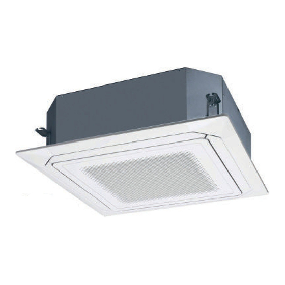
- Page 1 Installatiehandleiding CASETTE UNITS 90/90 KRL serie Binnenunit AUXG 36 KRLB AUXG 1 8 KRLB AUXG 45 KRLB AUXG 22 KRLB AUXG 54 KRLB AUXG 24 KRLB AUXG 30 KRLB Voor gebruik door de professional. Te bewaren door de gebruiker voor toekomstig gebruik.
-
Page 2: Table Of Contents
AIR CONDITIONER INSTALLATION MANUAL Cassette type PART No. 9381798070 [Original instructions] For authorized service personnel only. WARNING • The appliance shall be installed, operated and stored in a room with a fl oor area larger than X m². Amount of refrigerant charge Minimum room area M (kg) X (m... - Page 3 Precautions for using R32 refrigerant CAUTION 2-4 Presence of fi re extinguisher The basic installation work procedures are the same as conventional refrigerant (R410A, • If any hot work is to be conducted on the refrigeration equipment or any associated R22) models.
- Page 4 CAUTION CAUTION 4-Repair to intrinsically safe components 10-Decommissioning • Do not apply any permanent inductive or capacitance loads to the circuit without • Before carrying out this procedure, it is essential that the technician is completely ensuring that this will not exceed the permissible voltage and current permitted for familiar with the equipment and all its details.
-
Page 5: Product Specification
Explanation of symbols displayed on the indoor unit or outdoor unit. Name and Shape Q’ty Description This symbol shows that this appliance uses a fl ammable Installation manual (This book) refrigerant. WARNING If the refrigerant is leaked and exposed to an external igni- tion source, there is a risk of fi... -
Page 6: Electrical Requirement
2. 4. Electrical requirement 3. INSTALLATION WORK The indoor unit is powered from the outdoor unit. Do not power indoor unit from separate WARNING power source. • Do not turn on the power until all installation work is complete. WARNING •... -
Page 7: Installation Dimension
• Refrigerant piping and drain piping positions. Unit: mm 3. 2. Installation dimension • The ceiling rear height as shown in the fi gure. Unit: m Strong and durable ceiling Liquid pipe Gas pipe Drain pipe (Connect the 1.5 or 3 or more attached drain more... -
Page 8: Drain Installation
■ When lifting up drain: Hanging bolt (locally purchased) • Height of inclined pipe should be less than 850 mm from the ceiling. A rise dimension over Nut A (locally purchased) this range will cause leakage. • Lift up the pipe vertically at the position of 300 mm or less from the unit. Washer (Accessories) Downward gradient 300 mm or less... -
Page 9: Pipe Installation
■ Bending pipes 3. 5. Pipe installation • If pipes are shaped by hand, be careful not to collapse them. • Do not bend the pipes at an angle more than 90°. WARNING • When pipes are repeatedly bend or stretched, the material will harden, making it diffi cult to bend or stretch them any more. -
Page 10: Electrical Wiring
3.6.1. Wiring system diagram 3. 6. Electrical wiring Connection cable to outdoor unit WARNING Earth (ground) line • Electrical work must be performed in accordance with this Manual by a person certi- fi ed under the national or regional regulations. Be sure to use a dedicated circuit for Power line the unit. - Page 11 3.6.4. Wiring procedure (1) Remove the control box cover and wiring cover by loosening the screws. ■ Connection cable Wiring connecting port Control line Power line Wiring cover Connection cable Control box cover Earth (ground) Outdoor unit ■ Remote controller cable DIP switch Control box Print circuit board...
-
Page 12: Remote Controller Installation
● Dry contact terminal Cure the wiring connecting port and remote controller connecting port with paste or heat When a power supply is unnecessary at the input device you want to connect, use the Dry insulation so that insects or dust will not enter the unit contact terminal. -
Page 13: Remote Control Installation
5.2.3. Connection methods 6. 1. Group control Wire modifi cation • Remove insulation from wire attached to wire kit connector. CAUTION • Remove insulation from locally purchased cable. Use crimp type insulated butt Group control is only possible between units with remote controllers of the same type. connector to join fi... -
Page 14: Multiple Remote Control
(a) 2-wire type 7. FUNCTION SETTING DIP switch (RC AD SW)...Factory setting “00” Since the remote controller address settings are automatically confi gured, you do not Refer to the installation manual of remote controller for setting method. need to confi gure them. If confi... - Page 15 ■ Room temperature control for indoor unit sensor ■ Room temperature sensor switching Depending on the installed environment, correction of the room temperature sensor may (Only for wireless remote controller) When using the Wired remote controller temperature sensor, change the setting to "Both" be required.
-
Page 16: Check List
■ Setting record 10. FINISHING Record any changes to the settings in the following table. Function Setting Setting value CAUTION number Filter sign • After checking for gas leaks (refer to the Installation Manual of the outdoor unit), perform this section. Ceiling height •... - Page 17 Error display Error display Wired Wired remote remote TIMER ECONOMY TIMER ECONOMY Description Description OPERATION OPERATION controller controller lamp lamp lamp lamp lamp (green) lamp (green) Error code Error code (orange) (green) (orange) (green) Primary unit, secondary unit setup • Sub-cool Heat Ex. gas inlet ...