HP 8200 zl Installation And Getting Started Manual
Hide thumbs
Also See for 8200 zl:
- Reference manual (765 pages) ,
- Management and configuration manual (690 pages) ,
- Configuration manual (195 pages)
Table of Contents
Advertisement
Quick Links
Advertisement
Table of Contents

Related Manuals for HP 8200 zl


Summary of Contents for HP 8200 zl
- Page 1 HP 8200 zl Switches Installation and Getting Started Guide Power over Ethernet...
- Page 3 HP 8200 zl Switches Installation and Getting Started Guide...
- Page 4 J9534A Publication Number HP 20-port Gig-T PoE+ / 4-port SFP v2 zl Module J9535A 5998-2999 HP 20-port Gig-T PoE+ / 2-port 10-GbE SFP+ v2 zl Module J9536A June 2013 HP 24-port SFP v2 zl Module J9537A Applicable Products HP 8-port 10-GbE SFP+ v2 zl Module...
- Page 5 Regulatory Statements” in Appendix C.
-
Page 6: Table Of Contents
Overview of the 8200 zl Switches ........ - Page 7 1. Prepare the Installation Site ....... . 2-7 Cabling Infrastructure ........2-7 Installation Location .
- Page 8 3 Getting Started With Switch Configuration Recommended Minimal Configuration ......3-1 Using the Switch Setup Screen ....... . 3-2 Where to Go From Here .
- Page 9 Downloading New Code ........5-14 HP Customer Support Services ........5-14 Before Calling Support .
- Page 10 Crossover Twisted-Pair Cable for 10 Mbps or 100 Mbps Network Connection ....B-10 Cable Diagram ........B-10 Pin Assignments .
-
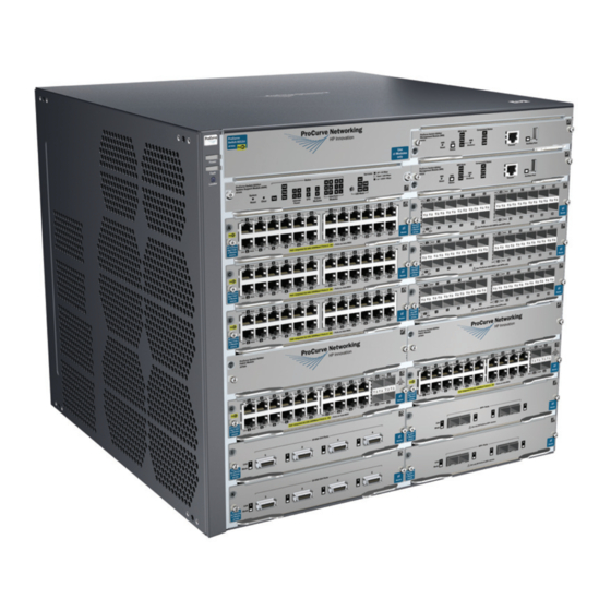
Page 12: Introducing The Hp 8200 Zl Switches
Introducing the HP 8200 zl Switches The HP 8200 zl switches are high-performance, high availability switch plat- forms that enable unified core-to-edge adaptive network solutions and deliver to market the industry’s first core switch with a lifetime warranty. They have platform and software high-availability features to ensure system continuity and enhanced network productivity. -
Page 13: Overview Of The 8200 Zl Switches
• One 1500W PoE+ zl Power Supply (J9306A) • With premium software activated The HP 8206 v2 zl Switch with Premium Software (J9640A) ships with the 8206 zl, 6-slot chassis (J9475A) and the following: • With premium software activated •... -
Page 14: 8212 Zl Switch
• One 1500W PoE+ zl Power Supply (J9306A) • With premium software activated The HP 8212 v2 zl Switch with Premium Software (J9641A) ships with the 8212 zl, 12-slot chassis (J8715A/B) and the following: • With premium software activated •... -
Page 15: Network Connectivity, Speeds And Technologies
Introducing the HP 8200 zl Switches Network Connectivity, Speeds and Technologies Network Connectivity, Speeds and Technologies These products support optional network connectivity as follows: Table 1-1. Optional Network Connectivity, Speeds and Technologies Transceiver Form-Factor and Connector Speed Technology Cabling SFP ("mini-GBIC") -
Page 16: Front Of The 8200 Zl Switches
Introducing the HP 8200 zl Switches Front of the 8200 zl Switches Front of the 8200 zl Switches Front of 8212 zl Switch, Base System Component Status LEDs Management Auxiliary Port Power Module Reset and Fault button, and Reset and Clear... -
Page 17: Front Of 8206 Zl Switch, Base System
Introducing the HP 8200 zl Switches Front of the 8200 zl Switches Front of 8206 zl Switch, Base System Component Status LEDs Management Auxiliary Port Power Module Reset and Fault button, and Status Reset and Clear LEDs Console Locator LED... -
Page 18: Switch And Module Leds
Introducing the HP 8200 zl Switches Front of the 8200 zl Switches Switch and Module LEDs As described in the following tables, there are LEDs on the switch chassis and on the switch modules that keep you informed of the status of the switch and the network connections. - Page 19 Introducing the HP 8200 zl Switches Front of the 8200 zl Switches Figure 1-6. Management Module LEDs Table 1-3. Management Module LEDs. State Meaning Auxiliary (green/ Blinking Indicates the switch is processing a USB command file. orange) For more green...
- Page 20 Introducing the HP 8200 zl Switches Front of the 8200 zl Switches Blinking The communication link with the SSM is bad or the SSM itself has failed. orange Module Status LED On green The Management Module is active and has passed all self-tests.
- Page 21 Introducing the HP 8200 zl Switches Front of the 8200 zl Switches Blinking Internal PoE fault. orange External load fault or denied PoE power. Blinking orange Switch temperature is normal. (green/orange) Blinking An over temperature condition has been detected. On green The cooling fans are operating normally.
- Page 22 Introducing the HP 8200 zl Switches Front of the 8200 zl Switches Modules A-L (green A module is installed in the switch module slot corresponding to the letter and - letters the module is undergoing or has passed self test. This also occurs when you corresponding to install a module when the switch is already powered on (“hot swap”).
-
Page 23: Led Mode Select Button And Indicator Leds
To optimize the amount of information that can be displayed for each of the switch ports, the 8200 zl switches use a Mode LED for each port. The operation of this LED is controlled by the LED Mode Select button on the switch chassis, and the current selection is indicated by the mode indicator LEDs near the button. -
Page 24: Console Port
This port is used to connect a console to the switch by using the serial cable supplied with the switch. This connection is described under “Connecting a Console to the Switch” in chapter 2, “Installing the the 8200 zl Switch”. The console is a full-featured interface that can be used to configure, monitor, and troubleshoot the switch. -
Page 25: Clear Button
Introducing the HP 8200 zl Switches Front of the 8200 zl Switches Press the Reset button also after changing the module type that is installed in any of the switch module slots while the switch is powered on. In this case, the switch must be reset to initialize the new module type. -
Page 26: Back Of The 8200 Zl Switches
Introducing the HP 8200 zl Switches Back of the 8200 zl Switches Back of the 8200 zl Switches Back of the 8212 zl Switch Grounding lug mounting holes Fan Power, Fault and Locator LEDs Slots for installing power supplies External PoE power connectors Figure 1-10. -
Page 27: Back Of The 8206 Zl Switch
Figure 1-11. Back of an 8206 zl Switch (shown with two zl Power Supplies) Power Supply The 8200 zl switches do not have a power switch. The switches are powered on when the power supply is connected to an active AC power source. The... -
Page 28: Switch Accessories
HP Power over Ethernet (PoE/PoE+) Planning and Implementation Guide. Switch Accessories Accessories of the 8200 zl switches include either a 6 or 12-slot chassis for installing any of the available zl Modules. The supported zl modules include: ■ 24-Port 10/100/1000 PoE+ zl Module (J9307A) -- which can provide Power over Ethernet (PoE+) power to 802.3at compliant (and some pre-stan-... - Page 29 12-port Gig-T / 12-port SFP v2 zl Module (J9637A) N o t e For detailed information about the zl modules, refer to the HP Switch zl Modules Installation Guide. For detailed information about PoE and PoE+ devices, refer to the HP Power over Ethernet (PoE/PoE+) Planning and Implementation Guide.
-
Page 30: Switch Features
Introducing the HP 8200 zl Switches Switch Features Switch Features The features of the 8200 zl switches include: modules can be installed in any order and in any combination and can be ■ “hot swapped” ■ supported transceivers can be hot swapped into the mini-GBIC zl Module high performance—With standard zl modules, the 8206 zl Switch has a... - Page 31 Management and Configuration Guide which is on the HP networking Web site. support for IEEE 802.3af standard, IEEE 802.3at standard, and pre-stan- ■...
-
Page 32: Installing The Hp 8200 Zl Switches
Installing the HP 8200 zl Switches The 8200 zl switches are easy to install. Each comes with an accessory kit that includes the brackets for mounting the switch in a standard 19-inch telco rack, or in an equipment cabinet. The switch has rubber feet already attached so they can be securely located on a horizontal surface. -
Page 33: Power Cords
Installing the HP 8200 zl Switches Power Cords Power Cords N o t e Power supplies for 8200 zl Switches must be ordered separately. The following power cords are provided with those power supplies. Power cord, one of the following: J8712A Power... -
Page 34: Installation Procedures
HP zl Modules. Depending on where you will install your 8200 zl switch, it may be easier to install the modules first. The modules are “hot swappable” though, so they may also be installed and removed after the switch is powered on. - Page 35 Installing the HP 8200 zl Switches Installation Procedures 6. Install the Grounding Wire (page 2-20). If a grounding wire is to be attached to the switch chassis, the grounding lug must be removed and a wire crimped to it and the grounding lug must be reinstalled.
-
Page 36: Installation Precautions
Installing the HP 8200 zl Switches Installation Procedures Installation Precautions To prevent personal injury, follow these precautions when installing the 8212 zl switch: ■ Due to product weight, two or more persons are required to handle W A R N I N G s and mount the 8212 zl switch. - Page 37 C a u t i o n s ■ If the switch is to be shipped in a rack, use only an HP 10000 series rack and a rail mounting kit (5070-0145) for each switch and ensure the power supplies have been removed before shipping.
-
Page 38: Prepare The Installation Site
On the sides of the switch, leave at least 7.6 cm (3 inches) for cooling. 2. Mount the Switch Chassis The HP 8200 zl switches have large, heavy chassis; therefore, HP networking recommends mounting the switch before populating it with modules or power supplies. - Page 39 Use a #1 Phillips (cross-head) screwdriver and attach the mounting brackets to the switch with the included 8-mm M4 screws. For the 8200 zl switches, each bracket is attached with four screws as shown in the following illustrated example. 8 mm M4 screws Figure 2-1.
- Page 40 Installing the HP 8200 zl Switches Installation Procedures Partially install a screw into the top hole of a pair of holes that are 0.5 inches apart in each rack/cabinet upright as shown in the illustration below. Ensure that the screws are at the same level in each upright.
-
Page 41: Horizontal Surface Mounting
Installing the HP 8200 zl Switches Installation Procedures Install the other screw into the upper hole in each bracket. Tighten these screws. install and tighten the other 12-24 screws Figure 2-4. Screws in Bracket Being Installed Horizontal Surface Mounting Place the switch on a table or other horizontal surface. Use a sturdy surface in an uncluttered area. -
Page 42: Install The Switch Modules
C a u t i o n Make sure you install only HP Switch zl Modules. Avoid any electrostatic discharge problems by handling the modules only by their bulkheads. - Page 43 Installing the HP 8200 zl Switches Installation Procedures Insert module into the guides and slide it in until it is fully inserted. Open extractor handles Figure 2-1. Module Being Installed in a Chassis Use the extractor handles to seat the module completely.
-
Page 44: Installing A Management Module Battery
Installing the HP 8200 zl Switches Installation Procedures Installing a Management Module Battery The battery on the management module is used to keep time for the internal switch clock. There is no indicator LED for when the battery dies. The only indication will be the internal clock will not keep the correct time. -
Page 45: Install The Power Supplies
Web site for more information. 4. Install the Power Supplies Both the 8212 zl switch and the 8206 zl switch can use any of these HP switch zl power supplies: ■ The J9306A, 1500W PoE+ zl Power Supply, which delivers the following PoE+: •... - Page 46 (that is: the sum total of all PoE or PoE+ supply capacity minus the largest supply, see chapter 2 and 4 of the HP Power over Ethernet (PoE/PoE+) Planning and Implementation Guide) loss of all PoE or PoE+ power may result.
- Page 47 Installing the HP 8200 zl Switches Installation Procedures C a u t i o n The switch power supplies are hot swappable; they can be installed while the switch is receiving power from the supply in the other slot. But, as indicated by the caution statement on the power supply, the supply must not be connected to AC power before being installed or removed.
-
Page 48: Verify The Switch Passes Self Test
Installing the HP 8200 zl Switches Installation Procedures Once the power supply is installed, tighten the four retaining screws that hold it in place. The screws can be tightened with either a flat-bladed or Torx T-10 screwdriver. Be careful not to overtighten the screws. - Page 49 Figure 2-9. Power Connector on Back of Switch N o t e The 8200 zl switches do not have a power on-off switch. It is powered on when the power cord is connected to the switch and to a power source.
-
Page 50: Led Behavior
Installing the HP 8200 zl Switches Installation Procedures Switch Chassis LEDs Switch Fault LED Switch Module LEDs: Link and Mode LEDs for each port Figure 2-10. Switch Fault, Module, and Chassis LEDs When the switch is powered on, it performs its diagnostic self test. The entire... -
Page 51: Install The Grounding Wire
Crimp the grounding lug to a properly grounded grounding wire. Re-attach the grounding lug to the switch with the two screws. Grounding lug screws Grounding lug Figure 2-11. Attaching Grounding Lug to the 8200 zl Switch 2-20... -
Page 52: Connect The Switch To A Power Source
AC power source. The HP ProCurve Switch zl Power Supply Shelf (EPS) (J8714A) is an accessory product for the 8200 zl switches. The EPS provides External Power- over-Ethernet (PoE) power for up to two 8200 zl switch products. -
Page 53: Eps Operation
900 watts of PoE power to each of the two EPS ports depending on which power supply is used. It is important to understand the PoE power requirements of the 8200 zl switches because if the PoE power is not planned and implemented correctly the end devices connected to the switch ports may not receive power if an internal switch PoE power supply should fail. - Page 54 Installing the HP 8200 zl Switches Installation Procedures ProCurve Switch zl Power Supply Shelf J8714A Power Power Fault Fault Power Supply EPS Port Status Status – Device Connected – Power Status Power Status LEDs Device Connected LEDs 2-23...
-
Page 55: Connecting The Power Supply Shelf
Installing the HP 8200 zl Switches Installation Procedures Connecting the Power Supply Shelf To Power Source 8200 zl To Power To Power Source Source EPS Cables Figure 2-12. Connecting the EPS to one 8200 zl switch 2-24... -
Page 56: Connect The Network Devices
9. Connect the Network Devices The type of network connections you will need to use depends on the types of switch modules you have installed in your 8200 zl switch. See the documen- tation accompanying the modules for cabling configurations and procedures for those modules. - Page 57 • Verify you have used the correct cable type for the connection: – for all twisted-pair connections, the RJ-45 connectors on the 8200 zl switch allow you to use either straight-through cable or crossover cable when the port is in the “Auto” configuration.
-
Page 58: 10. (Optional) Connect A Console To The Switch
Out-of-band: Connect a PC or VT-100 terminal, to be used as a console, directly to the switch using the serial cable that comes with the 8200 zl switch. If the PC or terminal has a 25-pin serial connector, you can use a readily available 9-pin to 25-pin serial cable, or attach a 9-to-25 pin straight- through adapter to the PC end of the cable. -
Page 59: Direct Console Access
Installing the HP 8200 zl Switches Installation Procedures If you want to operate the console using a different configuration, ensure you change the settings on both the terminal and on the switch. Change the switch settings first, then change the terminal settings, and reestablish the console session. -
Page 60: Console Cable Pinouts
Installing the HP 8200 zl Switches Installation Procedures Console Cable Pinouts The console cable has an RJ-45 male connector on one end and a DB-9 female connector on the other end. Table 2-2 describes the mapping of the RJ-45 to DB-9 pins. -
Page 61: Telnet Console Access
“Getting Started With Switch Configuration” for some basic configuration steps. For more detailed information, refer to the Management and Config- uration Guide which is on the HP networking Web site. Hot Swapping Switch Modules The switch modules can be “hot swapped” (except for the System Support... -
Page 62: Changing The Module Type
Installing the HP 8200 zl Switches Hot Swapping Switch Modules Changing the Module Type If you exchange a module with a different type of module though, for example a 10/100/1000-T zl Module is installed in place of a 4 port 10G X2 Module that... -
Page 63: Example Network Topologies
Installing the HP 8200 zl Switches Example Network Topologies Example Network Topologies This section shows a few example network topologies in which the 8200 zl switch can be implemented. Basic Connectivity 8212 zl Switch Phones, APs and other peripherals Figure 2-16. Basic Switch Connectivity The 8200 zl switch can provide basic network connectivity to a high number of PoE and PoE+ devices. -
Page 64: Use As An Edge Switch
In the above illustration, one 8200 zl switch, which can serve as a campus backbone or core switch, is connected to one 5400 zl switch and one 8200 zl switch at the edge. -
Page 65: Optimizing The 10-Gbe Port Configuration
Optimizing the 10-GbE Port Configuration with standard zl modules The 10-GbE ports on the HP 8200 zl switches are designed to deliver full 10 Gbps wire-speed to each port, where either one or two ports are in a linked state with another device. When three or four 10-GbE ports are in a linked state, when using an X2 (J8708A), CX4 (J8707A), or SFP+ (J9308A) module, the 10-GbE ports support an aggregate bandwidth of 28.8 Gbps across the... -
Page 66: Optimizing The 10-Gbe Port Configuration
The 10-GbE module (J9538A) delivers additional performance for zl switches. There is an increase in channel throughput and port density compared to the HP 4-Port 10-GbE CX4 zl Module (J8708A) and HP 4-Port 10-GbE X2 zl Module (J8707A). The 8200 zl has a fabric design that allows for optimal performance with 10-GbE v2 zl modules. - Page 67 If ports 1, 4, 6, and 8 are connected, the ports will share 23.4 Gbps of bandwidth between the four ports. The HP 8200 zl can support up to 4 wire rate interfaces on an 8 port 10-GbE module (J9538A).
-
Page 68: Getting Started With Switch Configuration
ProCurve Manager. For a listing of switch features available with and without an IP address, refer to “How IP Addressing Affects Switch Operation” in the Management and Configuration Guide which is on the HP networking Web site. -
Page 69: Using The Switch Setup Screen
DHCP or Bootp server. To use DHCP/Bootp instead of the manual method described in this chapter, see “DHCP/Bootp Operation” in the Management and Configuration Guide which is on the HP networking Web site. Using the Switch Setup Screen... - Page 70 Note: The IP address and subnet mask assigned for the switch must be compatible with the IP addressing used in your network. For more information on IP addressing, see the Management and Configuration Guide which is on the HP Web site.
-
Page 71: Where To Go From Here
For more information on the console, web browser, and SNMP management interfaces and all the features that can be configured on the 8200zl switches, see the HP Management and Configuration Guide at www.hp.com/networking/support. To Recover from a Lost Manager Password:... -
Page 72: Using The Ip Address For Remote Switch Management
Using the IP Address for Remote Switch Management With your 8200 zl switch, you can use the switch’s IP address to manage the switch from any PC that is on the same subnet as the switch. You can use either a TELNET session or a standard web browser to manage the switch. - Page 73 Figure 3-2. Example Switch Web Browser Interface - Status Overview For more information on using the web browser interface, please see the Management and Configuration Guide which is on the HP Web site. An extensive help system is also available for the web browser interface. To...
-
Page 74: Configuring The Procurve Wireless Edge Services Zl Module (J9051A)
Note ‘HP’ is used here as a generic prompt for all zl switches. To identify the slot in the zl switch where the module is installed, enter ■... - Page 75 Configuring the ProCurve Wireless Edge Services zl Module (J9051A) ■ To display the module’s IP address, enter: HP (wireless-services-id)# show ip interfaces The following example enters the wireless-services context of a module installed in Slot B of a zl switch and then displays the IP address assigned by...
-
Page 76: Configuring Vlans On The Zl Switch
See the Wireless Edge Services zl Module Supplement to the ProCurve zl Switch Management and Configuration Guide for detailed information to set up and configure VLANs on the zl switch for module communications. This www.hp.com/networking/support. manual is available at Determining a Module Configuration Backup Process The module’s configuration files are stored on the module, not on the zl switch,... -
Page 77: Configuring Wireless Lan Services
Getting Started With Switch Configuration Configuring the ProCurve Wireless Edge Services zl Module (J9051A) Configuring Wireless LAN Services To configure wireless LAN services on a wireless services-enabled zl switch, use one of the following management interfaces for the module: ■ Web browser interface —... -
Page 78: Replacing Components
For a complete list of parts and part numbers, see page 2-1. H o t S w a p p i n g The HP 8200 zl switches support “hot swapping.” Hot swapping is the ability to replace certain hardware components while the switch is operating, including a fan tray, power supply (if a second power supply is installed), and certain modules. -
Page 79: Replacing Power Supplies
Replacing Power Supplies Replacing Power Supplies If your HP E8200 zl switch is configured with redundant power supplies, you will not suffer any loss of traffic or performance if a power supply fails. Replace the failed component as soon as possible. One of the Internal Power LEDs on the management module will blink simultaneously with the switch Fault LED indicating which power supply failed. - Page 80 Replacing Components Replacing Power Supplies Using either a flat-bladed or Torx T-10 screwdriver loosen the retaining screws and remove the failed power supply. Figure 4-1. Power Supply Removal...
- Page 81 Replacing Components Replacing Power Supplies Insert the power supply into the opening. Slide it all the way in until it connects to the switch. The power supply face plate will be flush with the back face of the switch. tighten the four screws Figure 4-2.
-
Page 82: Replacing Fan Trays
Replacing Components Replacing Fan Trays Replacing Fan Trays When a fan fails the Fan Status LED on the switch chassis will blink simultaneously with the switch Fault LED. In this case, the entire fan tray needs to be replaced. You cannot replace individual fans. The fan tray is hot swappable. -
Page 83: Replacing The Management Module
If both Management Modules are removed from the switch at the same time, the switch will shutdown. If there is only one Management Module in the switch, HP networking recom- mends replacing the Management module, flash disk and battery (on the Management module) during scheduled down time. - Page 84 Replacing Components Replacing the Management Module 8. Tighten the retaining screws. Retaining Screws Extractor Handles Figure 4-4. Management Module Removal and Installation...
-
Page 85: Replacing The Management Module Compact Flash Card
Replacing Components Replacing the Management Module Compact Flash Card Replacing the Management Module Compact Flash Card The Compact Flash card is the primary non-volatile storage medium located on the management module that contains both the boot software and configuration files. When a Flash card fails the Flash status LED on the management module will blink simultaneously with the switch Fault LED. -
Page 86: Replacing The Services Module Compact Flash Card
Replacing Components Replacing the Services Module Compact Flash Card Replacing the Services Module Compact Flash Card The Compact Flash card is the primary non-volatile storage medium located on the Services Module that contains both the boot software and configuration files. When a Flash card fails the “CF Status” LED on the Services Module will blink simultaneously with the switch Fault LED. -
Page 87: Replacing The Services Module Disk Drive
Replacing Components Replacing the Services Module Disk Drive Replacing the Services Module Disk Drive The hard disk drive (HDD) is the primary storage medium located on the Services Module. When a disk drive fails the “HDD status” LED on the Services Module will blink simultaneously with the switch Fault LED. - Page 88 Replacing Components Replacing the Services Module Disk Drive 6. Using either side of the disk drive bracket, lift the disk drive out. Disconnected Disk drive Lift out retaining screws Figure 4-7. Services zl Module Disk Drive Removal Install the new disk drive and slide it forward to engage the connector. Re-install the 4 retaining screws.
- Page 89 Replacing Components Replacing the Services Module Disk Drive 4-12...
-
Page 90: Troubleshooting
Troubleshooting This chapter describes how to troubleshoot your 8200 zl switch. Note that this document describes troubleshooting mostly from a hardware perspective. You can perform more in-depth troubleshooting using the software tools available with the switch, including the full-featured console interface, the built-in web browser interface, and ProCurve Manager, the SNMP-based network management tool. - Page 91 Connecting to devices that have a fixed full-duplex configuration. ■ The RJ-45 ports on the 8200 zl switch are configured as “Auto.” That is, when connecting to attached devices, the switch will operate in one of two ways to determine the link speed and the communication mode (half duplex or full duplex): •...
- Page 92 ■ Check the port configuration. A port on your 8200 zl switch may not be operating as you expect because it has been put into a “blocking” state by Spanning Tree, GVRP (automatic VLANs), or LACP (automatic trunking).
-
Page 93: Diagnosing With The Leds
Troubleshooting Diagnosing with the LEDs Diagnosing with the LEDs Table 5-1 shows LED patterns on the switch and the switch modules that indicate problem conditions. Check in the table for the LED pattern you see on your switch Refer to the corresponding diagnostic tip on the next few pages. Table 5-1. - Page 94 You can remove and replace the module without having to power down the switch. Call your HP authorized dealer, or use the electronic support services from HP to get information on supported Switch zl modules.
- Page 95 As HP networking introduces new modunes for your HP Switch zl, you may have to update the switch with new operating code that supports the new module. The documentation that came with the module will indicate which version of the operating code is needed to support the module.
- Page 96 Reconnect the power supply to the AC power source. If the error indication reoccurs the slot after the supply is reinstalled, the power supply may be faulty. Call your HP corresponding to authorized dealer, or use the electronic support services from HP networking to get the blinking assistance.
- Page 97 • Verify you have used the correct cable type for the connection. – for any of the twisted-pair connections, in the default configuration (Auto), either a straight-through or a crossover cable can be used and the switch will automatically adjust its operation. See the “HP Auto-MDIX Feature” description on page B-7 for more information.
-
Page 98: Proactive Networking
Troubleshooting Proactive networking Proactive networking The 8200 zl switch has built-in management capabilities that proactively help you manage your network including: finding and helping you fix the most common network error conditions ■ (for example, faulty network cabling, and non-standard network topologies) ■... -
Page 99: Hardware Diagnostic Tests
Troubleshooting Hardware Diagnostic Tests Hardware Diagnostic Tests Reasons for Resetting the Switch Generally, you only need to reset the switch when it needs to recognize a change in its hardware or software (console) configuration. Some circumstances in which you will need to reset the switch are: ■... -
Page 100: Testing The Switch By Resetting It
Troubleshooting Hardware Diagnostic Tests Testing the Switch by Resetting It If you believe the switch is not operating correctly, you can reset the switch to test its circuitry and operating code. To reset a switch, either: ■ Unplug and plug in the power cord (power cycling) ■... -
Page 101: Testing Twisted-Pair Cabling
IEEE 802.3 Type 10Base-T, 100Base-TX, or 1000Base-T standards, as appropriate for the switch port type that the cable is connected to. The twisted-pair cables attached to the 8200 zl switch must be compatible with these standards.To verify your cable is compatible with these standards, use a qualified cable test device. -
Page 102: Restoring The Factory Default Configuration
For both the save and restore processes, you can use the console copy command. See the switch Management and Configura- tion Guide which is on the HP networking Web site. You can restore the factory default configuration either on the switch itself or through the switch console. -
Page 103: Downloading New Code
Troubleshooting Downloading New Code Downloading New Code When product enhancements occur for the 8200 zl switch, new code can be downloaded to the switch through several methods, for product enhance- ments and new features. Please see the Management and Configuration Guide which is on the HP networking Web site. -
Page 104: Physical
26.29 cm (10.35 in) Weight: • Switch 8206 zl (J9475A) 17.36 kg (38.28 lbs) Base System Electrical The HP Switch zl Internal Power Supplies automatically adjust to any voltage between 100-127 and 200-240 volts. J8712A J8713A AC voltage: 100-127 volts 200-240 volts... -
Page 105: Environmental
Specifications J9306A AC voltage: 110-127 volts 200-240 volts Maximum current: 13 A max 10 A max Frequency range: 50/60 Hz 50/60 Hz PoE/PoE+ output 300 W 900 W wattage: Environmental 8212 zl Switch Operating Non-Operating Temperature: 0C to 45C (32F to 113F) -40C to 70C (-40F to 158F) Relative humidity: 15% to 95% at 55C (131F) -
Page 106: Safety
Specifications Safety ■ EN60950 CSA 22.2 No. 60950 ■ ■ UL 60950 IEC 60950 ■ EMC compliance (Class A) Complies with: ■ VCCI EN55022/CISPR-22 ■ Technology Standards and Safety Compliance Table A-1. Technology Standards and Safety Compliance Laser safety information Technology Compatible EN/IEC... - Page 107 Specifications Table A-1. Technology Standards and Safety Compliance (Continued) Laser safety information Technology Compatible EN/IEC SFP+ Media with these IEEE standard ("mini-GBIC") Lasers Lasers Converter standards compliance Lasers Lasers 1000-LX IEEE 802.3z EN/IEC 60825 Class 1 Laser 1000BASE-LX Product Laser Klasse 1 1000-LH (not an IEEE EN/IEC 60825...
-
Page 108: B Switch Ports And Network Cables
Switch Ports and Network Cables Cabling and Technology Information Specifications Table B-1. Cabling Specifications 10 Mbps Operation Category 3, 4 or 5, 100-ohm unshielded twisted-pair (UTP) or shielded twisted-pair (STP) cable, complying with IEEE 802.3 10BASE-T specifications. 100 Mbps Operation Category 5, 100-ohm UTP or STP cable, complying with IEEE 802.3u 100BASE-TX specifications. - Page 109 Switch Ports and Network Cables Cabling and Technology Information Specifications Note on 1000BASE-T Cable Requirements. The Category 5 networking cables that work for 100BASE-TX connections should also work for 1000BASE-T, as long as all four-pairs are connected. But, for the most robust connections, you should use cabling that complies with the Category 5e specifications, as described in Addendum 5 to the TIA-568-A standard (ANSI/ TIA/EIA-568-A-5).
-
Page 110: Technology Distance Specifications
Switch Ports and Network Cables Cabling and Technology Information Specifications Technology Distance Specifications Table B-2. Technology Distance Specifications Technology Supported cable type Multimode fiber Supported distances modal bandwidth 100-FX multimode fiber up to 2,000 meters 100-BX single mode fiber 0.5 - 10,000 meters 1000-T twisted-pair copper up to 100 meters... - Page 111 Switch Ports and Network Cables Cabling and Technology Information Specifications Table B-2. Technology Distance Specifications(Continued) Technology Supported cable type Multimode fiber Supported distances modal bandwidth CX4 Media Converter 12-strand female-female multi- 150 MHz*km 1 - 50 meters mode fiber MPO ribbon cable 500 MHz*km 1 - 100 meters with MTP connectors, in a...
-
Page 112: Mode Conditioning Patch Cord
Switch Ports and Network Cables Mode Conditioning Patch Cord Mode Conditioning Patch Cord The following information applies to installations in which multimode fiber- optic cables are connected to a Gigabit-LX port or a 10-Gigabit LRM port. Multimode cable has a design characteristic called “Differential Mode Delay”, which requires the transmission signals be “conditioned”... -
Page 113: Installing The Patch Cord
Switch Ports and Network Cables Mode Conditioning Patch Cord Installing the Patch Cord As shown in the illustration below, connect the patch cord to the transceiver with the section of single mode fiber plugged in to the Tx (transmit) port. Then, connect the other end of the patch cord to your network cabling patch panel, or directly to the network multimode fiber. -
Page 114: Twisted-Pair Cable/Connector Pin-Outs
Twisted-Pair Cable/Connector Pin-Outs The HP Auto-MDIX Feature In the default configuration, “Auto”, the 10/100Base-TX ports on the 10/100-TX and PoE zl Modules used in the 8200 zl switches all automatically detect the type of port on the connected device and operate as either an MDI or MDI-X port, whichever is appropriate. -
Page 115: Straight-Through Twisted-Pair Cable For 10 Mbps Or 100 Mbps Network Connections
Straight-Through Twisted-Pair Cable for 10 Mbps or 100 Mbps Network Connections Because of the HP Auto-MDIX operation of the 10/100 ports on the switches, for all network connections, to PCs, servers or other end nodes, or to hubs or other switches, you can use straight-through cables. - Page 116 Switch Ports and Network Cables Twisted-Pair Cable/Connector Pin-Outs Cable Diagram Figure B-2. Straight-through Cable Diagram for 10/100 Mbps Network Connection N o t e Pins 1 and 2 on connector “A” must be wired as a twisted pair to pins 1 and 2 on connector “B”.
-
Page 117: Cable Diagram
Crossover Twisted-Pair Cable for 10 Mbps or 100 Mbps Network Connection The HP Auto-MDIX operation of the 10/100 ports on the switches also allows you to use crossover cables for all network connections, to PCs, servers or other end nodes, or to hubs or other switches. -
Page 118: Cable Diagram
Switch Ports and Network Cables Twisted-Pair Cable/Connector Pin-Outs Straight-Through Twisted-Pair Cable for 1000 Mbps Network Connections 1000Base-T connections require that all four pairs or wires be connected. Cable Diagram Figure B-4. Straight-through Cable Diagram for 1000 Mbps Network Connection N o t e Pins 1 and 2 on connector “A”... - Page 120 Switch Ports and Network Cables Twisted-Pair Cable/Connector Pin-Outs B-13...
-
Page 121: C Safety And Regulatory Statements
Safety and Regulatory Statements Safety Information Documentation reference symbol. If the product is marked with this symbol, refer to the product documentation to get more information about the product. WARNING A WARNING in the manual denotes a hazard that can cause injury or death. -
Page 122: Informations Concernant La Sécurité
Safety and Regulatory Statements Informations concernant la sécurité Informations concernant la sécurité Symbole de référence à la documentation. Si le produit est marqué de ce symbole, reportez-vous à la documentation du produit afin d'obtenir des informations plus détaillées. WARNING Dans la documentation, un WARNING indique un danger susceptible d'entraîner des dommages corporels ou la mort. -
Page 123: Hinweise Zur Sicherheit
Safety and Regulatory Statements Hinweise zur Sicherheit Hinweise zur Sicherheit Symbol für Dokumentationsverweis. Wenn das Produkt mit diesem Symbol markiert ist, schlagen Sie bitte in der Produktdokumentation nach, um mehr Informationen über das Produkt zu erhalten. WARNING Symbol für Dokumentationsverweis. Wenn das Produkt mit diesem Symbol markiert ist, schlagen Sie bitte in der Produktdokumentation nach, um mehr Informationen über das Produkt zu erhalten. -
Page 124: Considerazioni Sulla Sicurezza
Safety and Regulatory Statements Considerazioni sulla sicurezza Considerazioni sulla sicurezza Simbolo di riferimento alla documentazione. Se il prodotto è contrassegnato da questo simbolo, fare riferimento alla documen- tazione sul prodotto per ulteriori informazioni su di esso. WARNING La dicitura WARNING denota un pericolo che può causare lesioni o morte. -
Page 125: Consideraciones Sobre Seguridad
Safety and Regulatory Statements Consideraciones sobre seguridad Consideraciones sobre seguridad Símbolo de referencia a la documentación. Si el producto va marcado con este símbolo, consultar la documentación del producto a fin de obtener mayor información sobre el producto. WARNING Una WARNING en la documentación señala un riesgo que podría resultar en lesiones o la muerte. -
Page 126: Informações De Segurança
Safety and Regulatory Statements Informações de Segurança Informações de Segurança Símbolo de referência à documentação. Se o produto estiver marcado com este símbolo, consulte a documentação do produto para obter mais informações sobre ele. AVISO Um AVISO no manual indica um perigo que possa causar ferimentos ou morte. -
Page 127: Safety Information (Japan
Safety and Regulatory Statements Safety Information (Japan) Safety Information (Japan) -
Page 128: Safety Information (China
Safety and Regulatory Statements Safety Information (China) Safety Information (China) -
Page 129: Emc Regulatory Statements
Safety and Regulatory Statements EMC Regulatory Statements EMC Regulatory Statements U.S.A. FCC Class A This equipment has been tested and found to comply with the limits for a Class A digital device, pursuant to Part 15 of the FCC Rules. These limits are designed to provide reasonable protection against interference when the equipment is operated in a commercial environment. -
Page 130: Japan
VCCI Class A Korea Taiwan Regulatory Model Identification Number For regulatory identification purposes, the HP 8200 zl switches are assigned a Regulatory Model Number. The Regulatory Model Number for these switches is RSVLC- 0503. This regulatory number should not be confused with the marketing name (HP 8212 zl Switch), or product numbers (J9091A/B, J8715A/B, J9475A). -
Page 131: European Community
Hewlett-Packard Company 8000 Foothills Blvd., Roseville, CA 95747 U.S.A. Supplier's Address: declares, that the product Product Name and Model: HP E5406zl Switch, HP E5412zl Switch HP E8206zl Switch, HP E8212zl Switch J8697A, J8699A, J9447A, J8698A, J8700A, J9448A J9475A, J9477A, Product Number(s):... - Page 132 Safety and Regulatory Statements EMC Regulatory Statements C-12...
-
Page 133: D Recycle Statements
Recycle Statements Waste Electrical and Electronic Equipment (WEEE) Statements Disposal of Waste Equipment by Users in Private Household in the European Union This symbol on the product or on its packaging indicates that this product must not be disposed of with your other household waste. - Page 134 Recycle Statements Waste Electrical and Electronic Equipment (WEEE) Statements Laitteiden hävittäminen kotitalouksissa Euroopan unionin alueella Jos tuotteessa tai sen pakkauksessa on tämä merkki, tuotetta ei saa hävittää kotitalousjätteiden mukana. Tällöin hävitettävä laite on toimitettava sähkölaitteiden ja elektronisten laitteiden kierrätyspisteeseen. Hävitettävien laitteiden erillinen käsittely ja kierrätys auttavat säästämään luonnonvaroja ja varmista- maan, että...
- Page 135 Recycle Statements Waste Electrical and Electronic Equipment (WEEE) Statements Smaltimento delle apparecchiature da parte di privati nel territorio dell'Unione Europea Questo simbolo presente sul prodotto o sulla sua confezione indica che il prodotto non può essere smaltito insieme ai rifiuti domestici. È responsabilità dell'utente smaltire le apparecchiature consegnan- dole presso un punto di raccolta designato al riciclo e allo smaltimento di apparecchiature elettriche ed elettroniche.
- Page 136 Para obter mais informações sobre locais que reciclam esse tipo de material, entre em contato com o escritório da HP em sua cidade, com o serviço de coleta de lixo ou com a loja em que o produto foi adquirido.
- Page 137 10-GbE port configuration, optimizing … 2-34, 2-35 category 3, 4, 5 … B-7 connector pin-outs … B-7 crossover cable pin-out … B-10 HP Auto-MDIX feature … B-7 Act LED … 1-10 MDI-X to MDI connections … B-8, B-11 Actv LED … 1-9 MDI-X to MDI-X connections …...
- Page 138 … 2-22 resetting the switch for new module type … 2-31 operation … 2-22 switch modules … 2-30 EPS (PoE) power … 2-21 HP Auto-MDIX equipment cabinet feature description … B-7 mounting the switch in … 2-7 2 – Index...
- Page 139 Max … 1-10 MM status … 1-9 Mode network cables description … 1-12 HP Auto-MDIX feature … B-7 selecting the display … 1-12 twisted-pair connector pin-outs … B-7 mode select indicators … 1-10 twisted-pair, wiring rules … B-7 Module Status … 1-11 network devices showing error conditions …...
- Page 140 Reset button ports description … 1-13 console … 2-27 location on switch … 1-5, 1-6, 1-13 HP Auto-MDIX feature … B-7 restoring factory default configuration … 5-13 network connections … 2-25 resetting the switch Power LED factory default reset … 5-13 behavior during error conditions …...
- Page 141 IP address … 3-3 switch-to-switch or hub connection … B-10 field descriptions … 3-3 testing … 5-12 twisted-pair ports HP Auto-MDIX feature … B-7 telnet access to the console … 2-30, 3-5 terminal configuration … 2-27 Index – 5...
- Page 142 VT-100 terminal serial cable connection for … 2-28 wiring rules for twisted-pair cables … B-7 6 – Index...
- Page 144 To learn more, visit www.hp.com/networking/support © Copyright 201 1, 2013 Hewlett-Packard Development Company, L.P. The information contained herein is subject to change without notice. The only warranties for HP products and services are set forth in the express warranty statements accompanying such products and services.