Table of Contents
Advertisement
Quick Links
Advertisement
Table of Contents
Troubleshooting

Related Manuals for Sharp XR-J325XA


Summary of Contents for Sharp XR-J325XA
- Page 1 XR-J325XA XG-J326XA...
- Page 2 • •...
- Page 3 ®...
- Page 4 ■ • 64 65...
- Page 8 ® • ™ ® ® • • ® ® • ® • • •...
- Page 9 ■ ■ ■ ■ ■ ■ ■ ■ ■ ■ ■ ■ 50 51 ■ ■...
- Page 10 ■ ■ ■ ■ ■ ■ ■ ■ ■ •...
- Page 11 • ■ ■ ■ ■ ■ •...
- Page 12 25, 50 25, 50 lO Qk 38, 48 P R O Q...
- Page 13 •...
- Page 14 • P R O Q • • • • •...
- Page 15 • • • • • • • • •...
- Page 16 • • •...
- Page 17 P R O Q P R O Q 22 23...
- Page 18 ENTER INPUT COMPUTER COMPUTER INPUT • ' " STANDBY/ON STANDBY...
- Page 19 ■ • ■...
- Page 20 ■ ■ ➞ ➞ ■ ■ ➞ ➞...
- Page 21 χ χ χ χ χ χ χ χ χ 250 (635 cm) 553 cm (218 ) 311 cm (123 ) 10.2 m (33 6 ) 11.8 m (38 8 ) 69 cm 52 cm ( 20 200 (508 cm) 443 cm (174 ) 249 cm (98 ) 8.2 m (26 9 ) 9.4 m (30 11 )
- Page 22 • • • • •...
- Page 23 • • • • •...
- Page 24 • ø ø • •...
- Page 25 • • • •...
- Page 26 • • 21 24 STANDBY/ON • • • • • • STANDBY/ON STANDBY • •...
- Page 27 ENTER • •...
- Page 28 • • • 28 43 • • • •...
- Page 29 P R O Q • K E Y S T O N E • KEYSTONE • • KEYSTONE • KEYSTONE • •...
- Page 30 C O M P U T E R DVI S-VIDEO VIDEO / – INPUT • INPUT ' " INPUT V O L k k k k k / l l l l l l l l l l O/Qk k k k k VOLl l l l l l l l l l O •...
- Page 31 RESIZE • SVGA (800 × 600) 800 × 600 XGA (1024 × 768) — — 1024 × 768 SXGA (1152 × 864) 1152 × 864 768 × 576 1024 × 576 UXGA (1600 × 1200) 1600 × 1200 SXGA (1280 × 1024) 968 ×...
- Page 32 • •...
- Page 33 POINTER P R O Q EFFECT • Star Finger1 Finger2 Heart Underline P R O Q POINTER • SPOT E F F E C T • BREAK TIMER • 1/25 1/25 SPOT P R O Q • • • • ECO+QUIET •...
- Page 34 AUTO SYNC MAGNIFY • • MAGNIFY • FREEZE • ' " \ • F R E E Z E RETURN • × • • × PICTURE MODE PICTURE MODE • RETURN •...
- Page 35 PAGE UP/PAGE DOWN (上翻頁 / 下翻頁)按鈕 MOUSE(鼠標)/ ■ ' " \ | 調節按鈕 ( / / / ) ' " \ | ■ L-CLICK ■ R-CLICK R-CLICK(鼠標右鍵)按鈕 ■ L-CLICK R-CLICK L-CLICK(鼠標左鍵)按鈕 L-CLICK R-CLICK ■ PAGE UP PAGE DOWN ® ® ®...
- Page 36 数码抑噪 关 1级 2级...
- Page 38 • • •...
- Page 39 P R O Q P R O Q • • COMPUTER MENU/HELP •...
- Page 40 • ENTER ENTER • • ENTER • • MENU/HELP • •...
- Page 41 — — • • PICTURE MODE • • •...
- Page 42 ENTER ENTER ENTER • • ENTER • • • E N T E R •...
- Page 43 • • • • • • • •...
- Page 44 30 31 • R E S I Z E • • KEYSTONE • •...
- Page 45 —...
- Page 46 AUTO • SYNC • • •...
- Page 47 調節投影機功能(“投影調節”選擇表)(續) 選擇表操作n第38頁 a 設置或更改鍵代碼 7 音頻輸入 6 Monitor Output 選擇“系統鎖”,然後按ENTER(確 本功能用於為每個輸入模式選擇合適的音頻輸入 定)或Q。 端子組合。 選擇“下一步”,然後按ENTER(確 說明 可選的項目 定)。 A u d i o 1 A U D I O (音頻)1 輸入端子用作音頻輸 • 顯示出要求輸入鍵代碼的畫面。 入端子。 A U D I O (音頻)2 輸入端子用作音頻輸 A u d i o 2 按遙控器或投影機上的4 個按鈕,在...
- Page 48 鍵鎖功能 在“確認”處輸入同樣的鍵代碼。 鎖定投影機上的操控按鈕 使用本功能來鎖定投影機上的操控按鈕。 取消已經設置的鍵代碼 a 鎖定操控按鈕 • 在 上 述 步 驟 4 和 步 驟5 中 , 按 4 次 投 影 機 上 當正在打開投影機的電源時,按住投影機上的 的R。 ENTER(確定)按鈕約5秒鐘。 當設置了“系統鎖”時 • 當設置了“系統鎖”時,在打開電源時就會顯 屏幕顯示 示出鍵代碼輸入畫面。當出現該畫面時,請 輸入正確的鍵代碼來啟動投影機。 輸入鍵代碼的畫面 • 鍵鎖功能不影響用遙控器上的按鈕進行操控。 • 當投影機正在預熱時,不能使用鍵鎖功能。 a 取消鍵鎖...
- Page 49 用“幫助”選擇表排除故障 使用本功能可幫助排除在使用中出現的問題。 使用“幫助”選擇表功能 E N T E R (確定)按鈕 調節按鈕 (P/R/O/Q) 舉例︰當出現圖像閃爍時 M E N U / H E L P 在投射出電腦 RGB信號時,操作解決圖像閃爍。 (選擇表/幫助)按鈕 按MENU/HELP(選擇表/幫助)。 選 擇 ‘ 初 始 化 “ 自 動 同 步 ” 調 按O 或Q 來選擇“幫助”,然後按 節’,然後按ENTER(確定)。...
- Page 50 ■ ■ ■ ■ ■ ■ ■ ■ • STANDBY ON STANDBY...
- Page 51 ■ ■ ■ ■...
- Page 52 • • • • • • • • • • • • • • • • • • • •...
- Page 53 ■ ■ ■ ■ ■ ■ • • ■...
- Page 54 • • • • STANDBY/ON S TA N D B Y • • • •...
- Page 55 • • • • • • MENU HELP • ENTER STANDBY ON •...
- Page 56 • • • • • •...
- Page 57 • • •...
- Page 58 •...
- Page 59 C1 C2 C3 C4 P1 P2 P3 P4 • • • • – – • •...
- Page 60 → ←...
- Page 64 • • ✔ ✔ ✔ ✔ ✔ ✔ ✔ ✔ ✔ ✔ ✔ ✔ ✔ ✔ ✔ ✔ ✔ ✔ ✔ ✔ ✔ ✔ ✔ ✔ ✔ ✔ ✔ • • •...
- Page 65 • • – • • – • • • • • – • • – • • • • • • – • • – • – • • • • • • –...
- Page 66 – • • • • • • • • – • • • • • • • •...
- Page 68 XG-J326XA XR-J325XA 0.55’’ DLP XGA(1024 768) F2.5 - 2.6 1.15(f=20.4 - 23.5mm) DVI-I HDCP RGB/ D-sub ø 1(L/R) RGB/ D-sub ø USB B RS-232C 9 2500 2600 2200:1 200W 230W 100-240V 50/60Hz 2.9A 3.2A 267W(2.9W) 100V 303W(2.9W) 100V 259W(3.4W) 240V 293W(3.4W)
- Page 69 : mm...
- Page 71 Before using the projector, please read this operation manual carefully. Introduction ENGLISH ENGLISH IMPORTANT • For your assistance in reporting the loss Model No.: or theft of your Projector, please record the Model and Serial Number located on the bottom of the projector and retain this Serial No.: information.
- Page 72 Caution Concerning Lamp Replacement See “Replacing the Lamp” on page 52. ® This SHARP projector uses a DLP chip. This very sophisticated panel contains 786,432pixels (micromirrors). As with any high technology electronic equipment such as large screen TVs, video systems and video cameras, there are certain acceptable tolerances that the equipment must conform to.
-
Page 73: How To Read This Operation Manual
How to Read this Operation Manual ■ The specifications are slightly different, depending on the model. However, you can connect and operate all models in the same manner. • In this operation manual, the illustration and the screen display are simplified for explanation, and may differ slightly from the actual display. -
Page 74: Table Of Contents
Contents Preparing Introduction Operating with the Remote Control ..32 Displaying and Setting the How to Read this Operation Manual ..3 Break Timer ........32 Displaying the Pointer ......32 Contents ..........4 Using the Spot Function ...... 32 IMPORTANT SAFEGUARDS .... - Page 75 How to Use the Storage Case ..... 55 Connecting Pin Assignments ..... 56 RS-232C Specifications and Commands ........58 Computer Compatibility Chart .... 63 Troubleshooting ........64 For SHARP Assistance ...... 66 Specifications ........67 Dimensions ......... 68 Index ........... 69...
-
Page 76: Important Safeguards
IMPORTANT SAFEGUARDS CAUTION: Please read all of these instructions before you operate this product and save these instructions for later use. Electrical energy can perform many useful functions. This product has been engineered and manufactured to assure your personal safety. BUT IMPROPER USE CAN RESULT IN POTENTIAL ELECTRICAL SHOCK OR FIRE HAZARDS. - Page 77 15. Overloading 19. Replacement Parts Do not overload wall outlets, extension cords, or When replacement parts are required, be sure integral convenience receptacles as this can the service technician has used replacement result in a risk of fire or electric shock. parts specified by the manufacturer or have the same characteristics as the original part.
- Page 78 ■ Continuously watching the screen for long Internal cleaning should only be performed hours will cause eye strain. Take regular by a Sharp Authorized Projector Dealer or breaks to rest your eyes. Service Center. Avoid locations with extremes of Do not set up the projector in places temperature.
- Page 79 ■ If you are not to use the projector for a long ■ The power supply voltage and the shape of time or before moving the projector, make the plug may vary depending on the region certain you unplug the power cord from the or country you are using the projector in.
-
Page 80: Accessories
■ Remote receiver AN-MR2 ■ 3 RCA to mini D-sub 15 pin cable (3.0 m) AN-C3CP2 • Some of the optional accessories may not be available depending on the region. Please check with your nearest Sharp Authorized Projector Dealer or Service Center. -
Page 81: Part Names And Functions
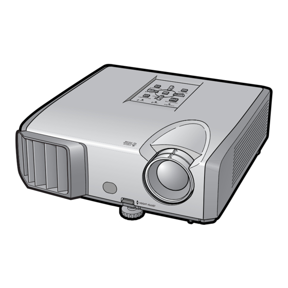
Part Names and Functions Numbers in refer to the main pages in this operation manual where the topic is explained. Projector Top View Power Lamp indicator 25, 50 25, 50 indicator Temperature warning indicator STANDBY/ON ECO+QUIET button button For lowering the noise For turning the of the cooling fan and power on and... -
Page 82: Rear View
Part Names and Functions (Continued) Numbers in refer to the main pages in this operation manual where the topic is explained. Rear View Terminals AUDIO 1 input terminal S-VIDEO input terminal Terminal for connecting video equipment with an COMPUTER/ S-video terminal. COMPONENT input terminal RS-232C terminal... - Page 83 STANDBY button ON button For turning the power For putting the projector into the standby mode. FREEZE button COMPUTER, DVI, For freezing images. S-VIDEO, VIDEO buttons AV MUTE button For switching to the For temporarily respective input modes. displaying a black BREAK TIMER button screen and turning For displaying the...
-
Page 84: Inserting The Batteries
Part Names and Functions (Continued) Inserting the Batteries Pull down the tab on the cover and remove the cover towards the direction of the arrow. Insert the batteries. • Insert the batteries making sure the polarities correctly match the m and n marks inside the battery compartment. Insert the lower tab of the cover into the opening, and lower the cover until it clicks in place. -
Page 85: Usable Range
Remote control sensor Usable Range The remote control can be used to control the projector within the ranges shown in the illustration. • The signal from the remote control can be re- 30° flected off a screen for easy operation. However, the effective distance of the signal may differ depending on the screen material. -
Page 86: Quick Start
Quick Start This section shows the basic operation (projector connecting with the computer). For details, see the page described below for each step. Setup and Projection In this section, connection of the projector and the computer is explained using one example. STANDBY/ON STANDBY button button... - Page 87 4. Adjust the projected image with the Setup Guide After the projector turns on, the Setup Guide appears. (When “Setup Guide” is set to “On”. See page 44.) Follow the steps in the Setup Guide and adjust the focus, height (angle) and picture size. After adjusting the focus, height (angle) and picture size, press ENTER to finish the Setup Guide.
-
Page 88: Setting Up The Projector
“Screen Size and Projection Distance”. Ceiling-mount Setup ■ It is recommended that you use the optional Sharp ceiling-mount adaptor and unit for this installation. Before mounting the projector, contact your nearest Sharp Authorized Pro- jector Dealer or Service Center to obtain the recommended ceiling-mount adaptor and unit (sold separately). -
Page 89: Projection (Prj) Mode
Projection (PRJ) Mode The projector can use any of the 4 projection modes shown in the diagram below. Select the mode most appropriate for the projection setting in use. (You can set the PRJ mode in “SCR-ADJ” menu. See page 44.) ■... -
Page 90: Screen Size And Projection Distance
Setting up the Projector (Continued) Screen Size and Projection Distance NORMAL Mode (4:3) Picture (Screen) size Projection distance [L] Distance from the lens center to the bottom of the image [H] Diag. [ χ ] Width Height Minimum [L1] Maximum [L2] 300 (762 cm) 610 cm (240 ) 457 cm (180 ) -
Page 91: Connecting The Projector To Other Equipment
• Depending on the computer you are using, an image may not be projected unless the computer’s external output port is switched on (e.g. Press “Fn” and “F5” keys simultaneously when using a SHARP notebook computer). Refer to the specific instructions in your computer's operation manual to enable your computer’s external output port. - Page 92 Connecting the Projector to Other Equipment (Continued) Terminal on the Terminal on Equipment Cable connected equipment projector Video equipment HDMI HDMI to DVI cable (commercially available) output terminal DVI-I DVI digital DVI Digital cable (commercially available) output terminal Component 3 RCA to mini D-sub 15 pin cable COMPUTER/ video (optional, AN-C3CP2)
- Page 93 ø3.5 mm stereo or mono audio cable AUDIO 1 ø3.5 mm audio output (commercially available or available terminal as Sharp service part QCNWGA038WJPZ) RCA audio cable (commercially available) RCA audio output terminal AUDIO 2 Cables for a camera or a video game...
-
Page 94: Controlling The Projector By A Computer
Controlling the Projector by a Computer When the RS-232C terminal on the projector is connected to a computer with a DIN-D-sub RS- 232C adaptor and an RS-232C serial control cable (cross type, commercially available), the com- puter can be used to control the projector and check the status of the projector. See page details. -
Page 95: Turning The Projector On/Off
Turning the Projector On/Off • When “Auto Restart” is set to “On”: Turning the Projector on If the power cord is unplugged from the outlet or the breaker switch is turned off when the projector is on, then the projector automati- Note that the connections to external equip- cally turns on when the power cord is plugged ment and power outlet should be done be-... -
Page 96: Image Projection
Image Projection Setup Guide screen About the Setup Guide After turning on the projector, the Setup Guide screen appears to assist you with projector setup. Guidance items 1 FOCUS 2 HEIGHT ADJUST 3 ZOOM Press ENTER to exit the Setup Guide screen. - Page 97 3 Adjusting the Height The height of the projector can be ad- justed using the adjustment feet at the front and rear of the projector. When the screen is above the projector, the projection image can be made higher by adjusting the projector. Lift the projector to adjust its height while lifting the HEIGHT HEIGHT...
-
Page 98: Correcting Trapezoidal Distortion
Image Projection (Continued) Correcting Trapezoidal Distortion Adjustment buttons (P/R/O/Q) When the image is projected either from the top or from the bottom towards the screen at an angle, the image becomes distorted trapezoidally. The function for correcting trapezoidal distortion is called Keystone Correction. -
Page 99: Switching The Input Mode
COMPUTER, DVI, Switching the Input Mode S-VIDEO, VIDEO buttons Select the appropriate input mode for the connected equipment. AV MUTE button Press COMPUTER, DVI, S-VIDEO or VIDEO on the remote control to select VOL +/– (Volume) the input mode. buttons •... -
Page 100: Resize Mode
Image Projection (Continued) Resize Mode This function allows you to modify or customize the resize mode to enhance the input image. De- pending on the input signal, you can choose a desired image. Press RESIZE. RESIZE • See page for setting on menu screen. button COMPUTER Main resolution... - Page 101 VIDEO/DTV VIDEO Input signal For 4:3 screen For 16:9 screen Video/DTV Image type NORMAL AREA ZOOM V-STRETCH BORDER STRETCH 4:3 aspect ratio 480I, 480P, 576I, 576P, NTSC, PAL, SECAM Squeeze Letter box 720P, 1035I, 1080I, 1080P 16:9 aspect ratio 16:9 aspect ratio 540P (4:3 aspect ratio in 16:9) : Cutout area on which images cannot be projected...
-
Page 102: Operating With The Remote Control
Operating with the Remote Control BREAK TIMER button Displaying the Pointer FREEZE button MAGNIFY buttons Press POINTER and press P/R/ O/Q on the remote control to move POINTER button the pointer. • Press EFFECT to change the pointer icon SPOT button (5 types). -
Page 103: Auto Sync (Auto Sync Adjustment)
Auto Sync Displaying an Enlar ged (Auto Sync Adjustment) Portion of an Image Graphs, tables and other portions of Auto Sync function works when detect- projected images can be enlarged. This ing input signal after the projector turns is helpful when providing more detailed explanations. -
Page 104: Using The Remote Control As The Wireless Computer Mouse
Remote receiver To USB terminal (optional, AN-MR2) To USB terminal USB cable (commercially available or available as Sharp service part QCNWGA014WJPZ) PAGE UP/ The mouse pointer can be oper- PAGE DOWN buttons ated in the following way after it MOUSE/Adjustment is connected. -
Page 105: Menu Items
Picture SCR - ADJ PRJ - ADJ Help Picture Mode Standard Contrast Contrast Bright Bright Color Color Tint Sharp Tint Sharp Blue Blue Page SEL./ADJ. ENTER PAGE 2 CLR Temp Picture SCR - ADJ PRJ - ADJ Help Page... - Page 106 Menu Items (Continued) “Screen adjustment (SCR-ADJ)” menu Main menu Sub menu Picture SCR - ADJ PRJ - ADJ Help Resize Normal SCR - ADJ Normal Resize Border Area Zoom Full Page Page Image Shift V-Stretch Dot By Dot Border Keystone Image Shift Area Zoom Stretch...
- Page 107 The items you can set with the “Help” “Help” menu menu Picture SCR - ADJ PRJ - ADJ Help “Help” menu n Page • Vertical stripes or flickering image appear There is no picture or audio Vertical stripes or flickering image appear Auto Sync Data image is not centered Clock...
-
Page 108: Using The Menu Screen
Using the Menu Screen ENTER button Adjustment buttons (P/R/O/Q) MENU/HELP button ENTER button Adjustment buttons (P/R/O/Q) RETURN button • Press RETURN to return to the previous screen when the menu is displayed. MENU/HELP button Menu Selections (Adjustments) Example: Adjusting “Bright”. •... - Page 109 Press P or R and select “Bright” Picture SCR - ADJ PRJ - ADJ Help to adjust. Picture Mode Picture Mode Standard Standard • The selected item is highlighted. Contrast Bright Blue CLR Temp BrilliantColor C.M.S. Setting C.M.S. Lamp Setting Bright Reset SEL./ADJ.
-
Page 110: Picture Adjustment ("Picture" Menu)
PRJ - ADJ Help Picture Mode Standard Picture Mode Standard Contrast Bright CLR Temp Color BrilliantColor Tint C.M.S. Setting Sharp C.M.S. Progressive 3D Progressive Blue Lamp Setting Bright Reset SEL./ADJ. ENTER SEL./ADJ. ENTER 1 Selecting the Picture Mode The default settings of each item when selecting Picture Mode... -
Page 111: Adjusting The Image
Tint* For making skin For making skin C.M.S.-Value Sets the brightness of the main tones purplish. tones greenish. colors. Sharp* For less For more Reset The adjustments of “Hue”, sharpness. sharpness. “Saturation” and “Value” of all Red* For weaker red. -
Page 112: Progressive
Selectable Brightness and Power consumption down enhancement will be enabled automati- items cally when the film source has been entered. XR-J325XA Approx. 70% Eco + Quiet • When the image is blurred or noisy, switch to the optimal mode. XG-J326XA Approx. -
Page 113: Adjusting The Projected Image ("Scr - Adj" Menu)
Adjusting the Projected Image (“SCR - ADJ” Menu) Menu operation n Page Picture SCR - ADJ PRJ - ADJ Help Resize Border Image Shift Keystone OSD Display Background Logo Setup Guide PRJ Mode Front Language English SEL./ADJ. ENTER 3 Keystone Correction 1 Setting the Resize Mode When the image is projected either from the top or from the bottom towards the screen at an angle,... -
Page 114: Selecting The Background Image
5 Selecting the Background 8 Selecting the On-screen Image Display Language Selectable items Description The projector can switch the on-screen display Logo Sharp logo screen language among 17 languages. Blue Blue screen None — 6 Selecting the Setup Guide Selectable items... -
Page 115: Adjusting The Projector Function ("Prj - Adj" Menu)
Adjusting the Projector Function (“PRJ - ADJ” Menu) Menu operation n Page Picture SCR - ADJ PRJ - ADJ Help 3 Auto Restart Function Auto Sync Auto Power Off Selectable Auto Restart Description items STANDBY Mode Standard System Sound If the power cord is unplugged from the Speaker outlet or the breaker switch is turned off Audio Input... -
Page 116: Audio Input
• If you lose or forget your keycode, contact your nearest Sharp Authorized Projector Dealer or Service Center (see page 66). Even if the product warranty is valid, the keycode reset will incur a charge. -
Page 117: Checking The Lamp Life Status
Keylock Function Enter the same keycode in “Re- confirm”. Locking the Operation Buttons on the Projector Use this function to lock the operation buttons To cancel the keycode that you have already on the projector. • Press R on the projector for four times in steps a Locking the Operation Buttons 4 and 5 above. -
Page 118: Troubleshooting With The "Help" Menu
Troubleshooting with the “Help” Menu This function advises you to solve the problems during usage. Utilizing the “Help” Menu Functions ENTER button Adjustment buttons Example: When image flickering appears (P/R/O/Q) Operation to solve image flickering when pro- jecting the computer RGB signal. MENU/HELP button Press MENU/HELP. -
Page 119: Maintenance
Maintenance Cleaning the projector Cleaning the lens ■ Ensure that you have unplugged the power ■ Use a commercially available blower or lens cord before cleaning the projector. cleaning paper (for glasses and camera lenses) ■ The cabinet as well as the operation panel is for cleaning the lens. -
Page 120: Maintenance Indicators
Maintenance Indicators ■ The warning lights (power indicator, lamp indicator and temperature warning indicator) on the projector indicate problems inside the projector. ■ If a problem occurs, either the temperature warning indicator or the lamp indicator will illuminate red, and the projector will enter standby mode. After the projector has entered standby mode, follow the procedures given below. - Page 121 (See page 8.) warning abnormally indicator high. • Cooling fan • Take the projector to your breakdown nearest Sharp Authorized • Internal circuit Projector Dealer or Service Center (see page 66) for failure • Clogged air intake repair. Lamp The lamp does •...
-
Page 122: Regarding The Lamp
Sharp Authorized Projector Dealer or Service Center. * If the new lamp does not light after replacement, take your projector to the nearest Sharp Authorized Projector Dealer or Service Center for repair. -
Page 123: Removing And Installing The Lamp Unit
Removing and Installing the Lamp Unit Warning! Lamp unit Optional • Do not remove the lamp unit from the projec- accessory AN-F212LP tor right after use. The lamp and parts around the lamp will be very hot and may cause burns or injury. -
Page 124: Resetting The Lamp Timer
Regarding the Lamp (Continued) Remove the lamp unit. • Loosen the securing screws from the lamp unit. Hold the lamp unit and pull it in the direction of the arrow. At this time, keep the lamp unit horizontal and do not tilt it. -
Page 125: Storing The Projector
Storing the Projector How to Use the Storage Case (XR-J325XA only) When storing the projector, attach the lens cap to the lens, and place it in the supplied storage case. Open the cover of the storage case. Info Lens cap Place the projector into the stor- age case. -
Page 126: Connecting Pin Assignments
Connecting Pin Assignments COMPUTER/COMPONENT input and COMPUTER/COMPONENT output Terminals : mini D- sub 15 pin female connector COMPUTER Input/Output COMPONENT Input/Output Pin No. Signal Pin No. Signal Video input (red) PR (CR) Video input (green/sync on green) Video input (blue) PB (CB) Not connected Not connected... - Page 127 RS-232C Terminal : mini DIN 9 pin female connector Pin No. Signal Name Reference Not connected Receive Data Input Connected to internal circuit Send Data Output Connected to internal circuit Not connected Signal Ground Connected to internal circuit Not connected Request to Send Connected to CS in internal circuit Clear to Send...
-
Page 128: Rs-232C Specifications And Commands
RS-232C Specifications and Commands Computer control A computer can be used to control the projector by connecting an RS-232C serial control cable (cross type, commercially available) to the projector. (See page for connection.) Communication conditions Set the serial port settings of the computer to match that of the table. Signal format: Conforms to RS-232C standard. - Page 129 0, 15, 30, 45 Life(Percentage) 0% – 100%(Integer) Name Model Name Check XRJ325XA/XGJ326XA Model Name Check XR-J325XA/XG-J326XA Projector Name Setting 1 OK or ERR (First 4 characters) *1 Projector Name Setting 2 OK or ERR (Middle 4 characters) *1 Projector Name Setting 3...
- Page 130 -30 – +30 OK or ERR Color -30 – +30 OK or ERR Tint -30 – +30 OK or ERR Sharp -30 – +30 OK or ERR CLR Temp -1 – +1 OK or ERR BrilliantColor 0 – +2 OK or ERR...
- Page 131 -30 – +30 OK or ERR Color -30 – +30 OK or ERR Tint -30 – +30 OK or ERR Sharp -30 – +30 OK or ERR CLR Temp -1 – +1 OK or ERR BrilliantColor 0 – +2 OK or ERR...
- Page 132 RS-232C Specifications and Commands (Continued) RETURN CONTROL CONTENTS COMMAND PARAMETER Standby mode Power ON (or 30-second startup time) OK or ERR Image Shift -96 – +96 OSD Display OK or ERR OK or ERR Video System Auto OK or ERR OK or ERR SECAM OK or ERR...
-
Page 133: Computer Compatibility Chart
Computer Compatibility Chart Computer • Multiple signal support Pixel Clock: 12-170 MHz Horizontal Frequency: 15-110 kHz, Sync signal: Compatible with TTL level Vertical Frequency: 45-85 Hz, • Compatible with sync on green signal The following is a list of modes that conform to VESA. However, this projector supports other signals that are not VESA standards. -
Page 134: Troubleshooting
Troubleshooting Problem Check Page • Projector power cord is not plugged into the wall outlet. – • Power to the external connected devices is off. • The selected input mode is wrong. 21–24 • Cables are incorrectly connected to the projector. •... - Page 135 Problem Check Page An unusual sound is • If the picture is normal, the sound is due to cabinet shrinkage caused – occasionally heard from by room temperature changes. This will not affect operation or the cabinet. performance. Maintenance indicator on •...
-
Page 136: For Sharp Assistance
For SHARP Assistance If you encounter any problems during setup or operation of this projector, first refer to the “Troubleshooting” section on pages and 65. If this operation manual does not answer your question, please contact the SHARP Service departments listed below. -
Page 137: Specifications
80% of the above values. Brightness is 2000Lm(XR-J325XA); 2080Lm(XG-J326XA);. As a part of policy of continuous improvement, SHARP reserves the right to make design and specification changes for product improvement without prior notice. The performance specifica- tion figures indicated are nominal values of production units. -
Page 138: Dimensions
Dimensions Units: mm... -
Page 139: Index
SCR - ADJ ............... 43 ENTER button ............38 Screen Size and Projection Distance ..... 20 Exhaust vent ............11, 49 Setup Guide ............26, 44 Sharp ............... 41 Fan Mode ..............46 Speaker ..............45 Fine Sync ..............48 SPOT button ............32 Focus ring .............. - Page 140 TINS-D617WJZZ...