
Related Manuals for Toro Workman 08303


Summary of Contents for Toro Workman 08303
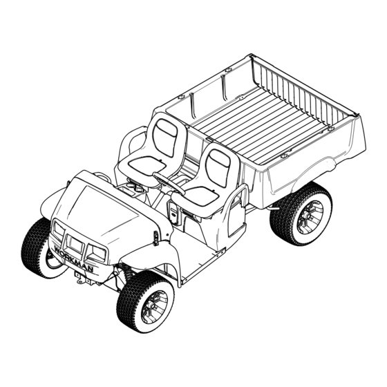
- Page 1 Form No. 3454-168 Rev A Workman ® MDX Lithium Utility Vehicle Model No. 08303—Serial No. 400000000 and Up Model No. 08303TC—Serial No. 400000000 and Up *3454-168* Register at www.Toro.com. Original Instructions (EN)
- Page 2 Visit www.Toro.com for product safety and operation training materials, accessory information, help finding a dealer, or to register your product. Whenever you need service, genuine Toro parts, or additional information, contact an Authorized Service Distributor or Toro Customer Service and have the model and serial numbers of your product ready.
-
Page 3: Table Of Contents
Contents Inspecting the Steering and Suspension Components ..........37 Adjusting the Front Wheel Alignment ....37 Safety ............... 4 Checking the Transaxle-Fluid Level ....38 Safety-Alert Symbol..........4 Changing the Transaxle Fluid ......39 General Safety ........... 4 Brake Maintenance ..........40 Safety and Instructional Decals ...... -
Page 4: Safety
Safety • Do not operate the machine without all guards and other safety protective devices in place and in good working order. Safety-Alert Symbol • Keep bystanders and children out of the operating area. Never allow children to operate the machine. The safety-alert symbol (Figure 2) shown in this... -
Page 5: Safety And Instructional Decals
Safety and Instructional Decals Safety decals and instructions are easily visible to the operator and are located near any area of potential danger. Replace any decal that is damaged or missing. decal140-4590 140-4590 1. Read the Operator’s Manual for battery information. decal115-2412 115-2412 1. - Page 6 decal147-4085 147-4085 1. Read the Operator’s 6. Alarm Manual for fuse information. decal147-4081 2. Horn 7. Headlights 147-4081 3. Display power 8. USB 1. Warning—read the 3. Crushing hazard, cargo 4. Main system B+ 9. Electrical shock hazard Operator's Manual. box—use the prop rod to support the cargo bed.
- Page 7 decal147-3846 147-3846 1. Turning on—1) Sit in the operator’s seat; 2) Turn the key 4. On switch to the O position; 3) Select a direction on the direction-selector switch; 4) Push down on the pedal. 2. Turning off—1) Release the pedal; 2) Engage the parking 5.
-
Page 8: Setup
Setup Loose Parts Use the chart below to verify that all parts have been shipped. Procedure Description Qty. Steering wheel Screw Install the steering wheel (Model Spring 08303TC only). Wheel cover Wheel clip – No parts required Charge the machine. –... -
Page 9: Charging The Machine
Checking the Fluid Levels and Tire Pressure No Parts Required Procedure Check the brake-fluid level before you first start the machine; refer to Checking the Brake-Fluid Level (page 40). Check the transaxle-fluid level before you first start the machine; refer to Checking the Transaxle-Fluid Level (page 38). -
Page 10: Product Overview
Product Overview Controls Control Panel Note: The steering wheel is removed from Figure for clarity. g421022 Figure 4 1. Steering wheel 5. Operator’s seat 2. Cargo bed 6. Charging port 3. Hood latch 7. Towing tongue g421043 Figure 5 4. Cargo-bed lever 1. - Page 11 Accelerator Pedal Horn Switch Use the accelerator pedal to vary ground speed Press the horn switch (Figure 5) to sound the horn. of the machine. Pressing down the accelerator pedal starts the machine. Pressing the pedal farther Light Switch increases ground speed. Releasing the pedal slows the machine, and the machine shuts off.
-
Page 12: Display
Display The display shows information about your machine, such as the operating status, various diagnostics, and other information about the machine (Figure g439782 Figure 7 Startup screen 1. Software revision 2. Number of equipped batteries on the machine g320256 Figure 6 1. - Page 13 The run screen with the current machine speed (Figure 11) appears when you are driving the machine. g413589 Figure 9 Charging screen g415320 Figure 11 1. Battery life 3. Estimated time to fully charge the machine 1. Current machine speed 2.
- Page 14 When the cold battery indicator (Figure 13) flashes Icon Descriptions on the run screen during operation, the machine performance changes until the battery temperature Direction—F position ORWARD is above 0°C (32°F). Transport—N position EUTRAL Direction—R position EVERSE Parking brake is engaged. Hour meter Battery voltage Battery charge level...
- Page 15 Supervisor Speed-Limit Switch The supervisor speed-limit switch (Figure 15), located under the hood, has 2 positions: P ERFORMANCE and E . Rotate the switch clockwise to the CONOMY position to limit the maximum machine CONOMY speed to 18 km/h (11 mph). Rotate the switch counterclockwise to the P position to ERFORMANCE...
-
Page 16: Specifications
25 cm (10 inches) inside Attachments/Accessories A selection of Toro approved attachments and accessories is available for use with the machine to enhance and expand its capabilities. Contact your Authorized Service Dealer or authorized Toro distributor or go to www.Toro.com for a list of all approved attachments and accessories. -
Page 17: Before Operation
Operation smoother ride, and to minimize tire marks on the ground. • Use higher air pressure in the tires for Before Operation carrying heavier payloads at higher speeds. If necessary, adjust the air pressure in the tires by adding or removing air in the tires. Before Operation Safety General Safety •... - Page 18 Before you start the machine, ensure that the • Use accessories and attachments approved by parking brake is engaged and you are in the The Toro Company only. operating position. • You and your passengers should remain seated Slope Safety whenever the machine is moving.
-
Page 19: Operating The Cargo Bed
Operating the Cargo Bed • If you begin to lose momentum while climbing a slope, gradually engage the brakes and slowly reverse the machine straight down the slope. Raising the Cargo Bed • Turning while going up or down a slope can be dangerous. - Page 20 Opening the Tailgate Ensure that the cargo bed is down and latched. Lift up the finger pulls at the back panel of the tailgate (Figure 20). g014860 Figure 18 1. Lever 3. Detent slot 2. Prop rod Pull the prop rod into the detent slot to secure the bed (Figure 19).
-
Page 21: Monitoring The Battery-System Charge Level
Monitoring the Battery-System Charge Level Refer to the display to determine the battery-system charge level; refer to Display (page 12). Understanding the Low g024491 Battery-Level Advisories Figure 21 1. Rotate the tailgate to 3. Hinge area If the battery level becomes too low (i.e., below 10%), approximately the 45°... -
Page 22: Loading The Cargo Bed
Loading the Cargo Bed Material Density Maximum Cargo Box Capacity (on level ground) Use the following guidelines when loading the cargo bed and operating the machine: Full Gravel, dry 1522 kg/m lb/ft • Observe the weight capacity of the machine and Gravel, wet 1922 kg/m (120... -
Page 23: After Operation
• Refer to an authorized Toro distributor to service Maintenance and Storage or replace a battery. • Do not disassemble the charger. -
Page 24: Hauling The Machine
Towing the Machine • Do not operate the charger with a damaged cord or plug. Contact an authorized Toro distributor to obtain a replacement cord. In case of an emergency, you can tow the machine for a short distance; however, this should not be a •... -
Page 25: Transporting The Lithium-Ion Batteries
3-prong grounded plug (type B). If the plug does not fit into the wall receptacle, other grounded plug types are available; contact an authorized Toro distributor. Insert the wall plug end of the power-supply cord into a grounded electrical outlet. - Page 26 Charging the Lithium-Ion Batteries CAUTION Attempting to charge the batteries with a charger not provided by Toro can result in excessive heat and other related product malfunctions, which can lead to property damage and/or injury. Use the Toro-provided chargers to charge the batteries.
-
Page 27: Maintenance
Such use • To ensure that the entire machine is in good could void the product warranty of The Toro® condition, keep all hardware properly tightened. Company. Recommended Maintenance Schedule(s) - Page 28 Note: Download a free copy of the electrical schematic by visiting www.Toro.com and searching for your machine from the Manuals link on the home page. WARNING Failing to properly maintain the machine could result in premature failure of machine systems, causing possible harm to you or bystanders.
-
Page 29: Daily Maintenance Checklist
Daily Maintenance Checklist Duplicate this page for routine use. Maintenance Check Item For the week of: Monday Tuesday Wednesday Thursday Friday Saturday Sunday Check the brake and parking brake operation. Check the direction-selector operation. Check the brake-fluid level. Check for unusual operating noises. -
Page 30: Pre-Maintenance Procedures
Pre-Maintenance Procedures Preparing the Machine for Maintenance Park the machine on a level surface. Ensure that the parking brake is engaged. Shut off the machine and remove the key. g312722 Lifting the Machine Figure 27 1. Rear lifting points DANGER The machine may be unstable when using a jack. -
Page 31: Lubrication
Lubrication Greasing the Front Wheel Bearings Service Interval: Every 300 hours Grease specification: Mobilgrease XHP™-222 Removing the Hub and Rotor Lift the front of the machine and support it with jack stands. g033047 Figure 30 Remove the 4 lug nuts that secure the wheel to the hub (Figure 29). - Page 32 Greasing the Wheel Bearings Remove the outboard bearing and bearing race from the hub (Figure 33). g033049 Figure 32 1. Spindle 2. Hub and rotor assembly g033050 Wipe clean the spindle with a rag. Figure 33 Repeat steps through to the hub and rotor at 1.
- Page 33 Installing the Hub and Rotor Apply a light coat of the specified grease to the spindle (Figure 34). g033054 Figure 35 1. Cotter pin 3. Dust cap 2. Nut retainer g033051 Figure 34 Install the cotter pin and bend each legs around 1.
-
Page 34: Electrical System Maintenance
Periodically examine the cords for damage, and replace them when necessary with Toro-approved Do not open the battery. If you are having problems parts. with a battery, contact your authorized Toro distributor for assistance. Locating the Fuses The 12 V and 60 V fuses... -
Page 35: Maintaining The Headlights
g428649 Figure 37 1. Horn (20 A) 5. USB (5 A) 2. Display power (10 A) 6. Headlights (7.5 A) 3. Main system B+ (10 A) 7. Alarm (5 A) 4. DC to DC (20 A) 8. Telematics (5 A) The battery charger (30 A) and machine power (200 A) fuses (Figure... - Page 36 Adjusting the Headlights Use the following procedure to adjust the headlight beam position whenever a headlight assembly is replaced or removed. Park the machine on a level surface with the headlights approximately 7.6 m (25 ft) from a wall (Figure 40).
-
Page 37: Drive System Maintenance
Drive System Maintenance Maintaining the Tires Service Interval: Every 100 hours—Check the condition of the tires and rims. Every 100 hours—Torque the wheel-lug nuts. Inspect the tires and rims for signs of wear and damage. Note: Operating accidents, such as hitting curbs, can damage a tire or rim and also disrupt wheel alignment, so inspect tire condition after g415333... -
Page 38: Checking The Transaxle-Fluid Level
2 to 3 m (6 to 10 ft) and then straight forward to the original starting position. This allows the suspension to settle into the operating position. Adjusting the Camber Owner provided tools: spanner wrench, Toro Part g009235 132-5069; refer to your authorized Toro distributor. Figure 44... -
Page 39: Changing The Transaxle Fluid
Remove the fill plug (Figure 47). Remove the drain plug and allow the fluid to drain completely. Install the drain plug and torque it to 12 to 19 N∙m (9 to 14 ft-lb). Fill the transaxle with the specified fluid through the fill-plug hole until it runs out of the fill hole. -
Page 40: Brake Maintenance
Brake-fluid type: DOT 3 Service Interval: Every 1,000 hours Raise the hood to access to the master brake cylinder and reservoir (Figure 48). Contact your authorized Toro distributor. g033037 Figure 48 1. Filler neck (reservoir) 3. DOT 3 brake fluid 2. Reservoir cap... -
Page 41: Chassis Maintenance
Chassis Maintenance Cleaning Adjusting the Cargo-Bed Washing the Machine Latches Service Interval: Before each use or daily—Wash the machine. If the cargo-bed latch is out of adjustment, the cargo Wash the machine as needed using water alone bed vibrates up and down as you drive the machine. or with a mild detergent. -
Page 42: Storage
Note: Paint is available from your authorized does not turn back on unless the charger is Toro distributor. disconnected and reconnected. Cover the machine to protect it and keep it clean. - Page 43 Notes:...
- Page 44 Notes:...
- Page 45 While the exposure from Toro products may be negligible or well within the “no significant risk” range, out of an abundance of caution, Toro has elected to provide the Prop 65 warnings. Moreover, if Toro does not provide these warnings, it could be sued by the State of California or by private parties seeking to enforce Prop 65 and subject to substantial penalties.
- Page 46 The Toro Company (“Toro”) respects your privacy. When you purchase our products, we may collect certain personal information about you, either directly from you or through your local Toro company or dealer. Toro uses this information to fulfil contractual obligations - such as to register your warranty, process your warranty claim or to contact you in the event of a product recall - and for legitimate business purposes - such as to gauge customer satisfaction, improve our products or provide you with product information which may be of interest.
- Page 47 Battery Limited Warranty Battery The rechargeable lithium-ion battery is warranted to be free from defects in materials and workmanship for a period of years as listed in the table below. Over time, battery consumption reduces the amount of energy capacity (MWh) available per full charge. Energy consumption varies due to operating characteristics, accessories, turf, terrain, adjustments, and temperature.
- Page 48 Countries Other than the United States or Canada Customers who have purchased Toro products exported from the United States or Canada should contact their Toro Distributor (Dealer) to obtain guarantee policies for your country, province, or state. If for any reason you are dissatisfied with your Distributor's service or have difficulty obtaining guarantee information, contact your Authorized Toro Service Center.