Table of Contents
Advertisement
TECHNICAL & SERVICE MANUAL
Indoor unit
[Model Name]
TPLFYP005FM140A
TPLFYP008FM140A
TPLFYP012FM140A
TPLFYP015FM140A
TPLFYP018FM140A
Model name
indication
INDOOR UNIT
R410A
No. TCHT003
CONTENTS
1. SAFETY PRECAUTION .......................... 2
2. PARTS NAMES AND FUNCTIONS ........ 4
3. SPECIFICATIONS ................................. 13
4. 4-WAY AIR FLOW SYSTEM ................. 15
5. OUTLINES AND DIMENSIONS ............ 17
6. WIRING DIAGRAM ............................... 18
7. REFRIGERANT SYSTEM DIAGRAM ...... 19
8. MICROPROCESSOR CONTROL .......... 20
9. TROUBLESHOOTING .......................... 27
10. DISASSEMBLY PROCEDURE ........... 35
PARTS CATALOG (TCBT003)
April 2019
Advertisement
Table of Contents

Related Manuals for Mitsubishi Electric TRANE TPLFYP005FM140A


Summary of Contents for Mitsubishi Electric TRANE TPLFYP005FM140A
-
Page 1: Table Of Contents
April 2019 No. TCHT003 TECHNICAL & SERVICE MANUAL R410A Indoor unit [Model Name] TPLFYP005FM140A TPLFYP008FM140A TPLFYP012FM140A TPLFYP015FM140A TPLFYP018FM140A CONTENTS 1. SAFETY PRECAUTION ......2 2. PARTS NAMES AND FUNCTIONS ..4 3. SPECIFICATIONS ......... 13 4. 4-WAY AIR FLOW SYSTEM ....15 5. -
Page 2: Safety Precaution
SAFETY PRECAUTION CAUTIONS RELATED TO NEW REFRIGERANT Cautions for units utilizing refrigerant R410A Use the following tools specifically designed for Do not use the existing refrigerant piping. use with R410A refrigerant. The old refrigerant and lubricant in the existing piping The following tools are necessary to use R410A refrigerant. - Page 3 [1] Cautions for service (1) Perform service after recovering the refrigerant left in unit completely. (2) Do not release refrigerant in the air. (3) After completing service, charge the cycle with specified amount of refrigerant. (4) When performing service, install a filter drier simultaneously. Be sure to use a filter drier for new refrigerant.
-
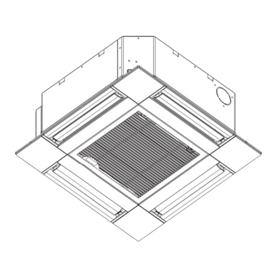
Page 4: Parts Names And Functions
PARTS NAMES AND FUNCTIONS 2-1. Indoor Unit Filter Removes dust and pollutants Horizontal Air Outlet from drawn in air. Sets horizontal airflow automatically during cooling or dehumidifying. Grille Auto Air Swing Vane Disperses airflow up and down and adjusts the angle of airflow direction. - Page 5 2-2-1. Wired Remote Controller <TAR-40MAA> Controller interface The functions of the function buttons change depending on the screen. Refer to the button function guide that appears at the bottom of the LCD for the functions they serve on a given screen. When the system is centrally controlled, the button function guide that corresponds to the locked button will not appear.
- Page 6 Display The main display can be displayed in two different modes: “Full” and “Basic”. The factory setting is “Full”. To switch to the “Basic” mode, change the setting on the Main display setting. (Refer to operation manual included with remote controller.) <Full mode>...
- Page 7 Main menu Press the button. MENU Move the cursor to the desired item with the buttons, and press the button. SELECT Operation Vane · Louver · Vent. (Lossnay) High power Comfort Manual vane angle 3D i-see Sensor Timer menu Timer ON/OFF timer Auto-OFF timer Weekly timer...
- Page 8 Continue from the previous page. Maintenance menu Error information Filter information Cleaning Auto descending panel Descending operation Descending adjustment Service menu Test run menu Test run Drain pump test run Maintenance information Model name input Serial No. input Dealer information input Initialize maintenance info.
- Page 9 Main menu list Main Setting and display items Setting details menu Operation Vane · Louver · Vent. Use to set the vane angle. (Lossnay) • Select a desired vane setting from 5 different settings. Use to turn ON/OFF the louver. •...
- Page 10 Main Setting and display items Setting details menu Initial Basic Main/Sub When connecting 2 remote controllers, one of them needs to be designated as setting setting a sub controller. Clock Use to set the current time. Daylight Set the daylight saving time. saving time Administrator The administrator password is required to make the settings for the following...
- Page 11 2-2-2. Wired Remote Controller <TAC-YT53CRAU> Note: The phrase "Wired remote controller" in this manual refers only to the TAC-YT53CRAU. If you need any information for the other remote controller, please refer to either the installation manual or initial setting manual which are included in remote controller's box.
- Page 12 2-3. Wireless remote controller Transmission area Not available Remote controller display Battery replacement indicator Set Temperature buttons OFF/ON button Mode button (Changes operation mode) Fan Speed button (Changes fan speed) ���� button (Changes up/down ���� direction) i-see button Timer ON button Menu button Timer OFF button SET/SEND button...
-
Page 13: Specifications
SPECIFICATIONS 3-1. SPECIFICATIONS Service Ref. TPLFYP005FM140A TPLFYP008FM140A TPLFYP012FM140A TPLFYP015FM140A TPLFYP018FM140A power source single phase, 208/230V, 60 Hz cooling capacity *1 BTU/h 5,000 8,000 12,000 15,000 18,000 Power input kW 0.02 0.02 0.02 0.03 0.04 Current input A 0.19 0.22 0.23 0.28 0.40 Heating capacity... - Page 14 3-2. ELECTRICAL PARTS SPECIFICATIONS Service ref. TPLFYP005FM140A TPLFYP008FM140A TPLFYP012FM140A TPLFYP015FM140A TPLFYP018FM140A Symbol Parts name Thermistor (Room temperature TH21 Resistance 30°F/15.8", 50°F/9.6", 70°F/6.0", 80°/4.8", 90°F/3.9", 100°F/3.2" detection) Thermistor (Pipe temperature TH22 Resistance 30°F/15.8", 50°F/9.6", 70°F/6.0", 80°/4.8", 90°F/3.9", 100°F/3.2" detection/Liquid) Thermistor (Pipe temperature TH23 Resistance 30°F/15.8", 50°F/9.6", 70°F/6.0", 80°/4.8", 90°F/3.9", 100°F/3.2"...
-
Page 15: Way Air Flow System
4-WAY AIR FLOW SYSTEM 4-1. FRESH AIR INTAKE (Location for installation) At the time of installation, use the duct holes (cut out) located at the positions shown in following diagram, as and when required. Fresh air intake Detail drawing of fresh air intake 5-1/2 Burring hole Cut out hole... - Page 16 4-4. FIXING HORIZONTAL VANE Horizontal vane of each air outlet can be fixed according to the environment where it is installed. Setting procedures 1) Turn off a main power supply (Turn off a breaker). 2) Disconnect the vane motor connector of the direction of the arrow with pressing the unlocking button as shown in figure below.
-
Page 17: Outlines And Dimensions
OUTLINES AND DIMENSIONS TPLFYP005FM140A TPLFYP008FM140A TPLFYP012FM140A TPLFYP015FM140A TPLFYP018FM140A Unit: inch(mm) TCHT003... -
Page 18: Wiring Diagram
WIRING DIAGRAM TPLFYP005FM140A TPLFYP008FM140A TPLFYP012FM140A TPLFYP015FM140A TPLFYP018FM140A TCHT003... -
Page 19: Refrigerant System Diagram
REFRIGERANT SYSTEM DIAGRAM TPLFYP005FM140A TPLFYP008FM140A TPLFYP012FM140A TPLFYP015FM140A TPLFYP018FM140A Strainer (#50mesh) Thermistor (Pipe temperature detection/Gas) TH23 Gas pipe Thermistor (Pipe temperature detection/Liquid) TH22 Flare connection Liquid pipe Heat exchanger Linear expansion valve Strainer1 (#50mesh) Strainer2 (#100mesh) Strainer (#100mesh) Thermistor (Room temperature detection) TH21 Unit: inch (mm) Gas pipe [1/2(12.7) -
Page 20: Microprocessor Control
MICROPROCESSOR CONTROL INDOOR UNIT CONTROL 8-1. COOL OPERATION <How to operate> 1 Press ON/OFF button. 2 Press [F1] button to display COOL. 3 Press [F2] [F3] button to set the set temperature. NOTE: The settable temperature range varies with the model of outdoor units and remote controller. - Page 21 Control Mode Control Details Remarks 3. Drain pump 3-1. Drain pump control • The drain pump will always run when the unit is in COOL or DRY mode. (Regardless of the thermo ON/OFF) • Whenever the operation is changed over to the other modes (including Stop), the drain pump will stop pumping after approximately 3 minutes.
- Page 22 8-2. DRY OPERATION <How to operate> 1 Press ON/OFF button. 2 Press [F1] button to display DRY. 3 Press [F2] [F3] button to set the set temperature. RETURN SELECT MENU HOLD <How to operate> 1 Press POWER ON/OFF button. 2 Press the operation MODE button to display DRY. 3 Press the TEMP.
- Page 23 8-3. FAN OPERATION <How to operate> 1 Press ON/OFF button. 2 Press [F1] button to display FAN. RETURN SELECT MENU HOLD <How to operate> 1 Press POWER ON/OFF button. 2 Press the operation MODE button to display FAN. Control Mode Control Details Remarks 1.
- Page 24 8-4. HEAT OPERATION <How to operate> 1 Press ON/OFF button. 2 Press [F1] button to display HEAT. 3 Press [F2] [F3] button to set the set temperature. NOTE: The settable temperature range varies with the model of outdoor units and remote controller. RETURN SELECT MENU HOLD...
- Page 25 Control Mode Control Details Remarks 2-1. Hot adjust mode "STAND BY" will be displayed during the The fan controller becomes the hot adjuster mode for the following conditions. hot adjust mode. 1 When starting the HEAT operation 2 When the temperature adjustment function changes from OFF to ON. The step change 3 When release the HEAT defrosting operation of A to B will not be...
- Page 26 8-5. AUTO OPERATION [AUTOMATIC COOL/HEAT CHANGE OVER OPERATION] <How to operate> 1 Press ON/OFF button. 2 Press [F1] button to display AUTO. 3 Press [F2] [F3] button to set the set temperature. NOTE: The settable temperature range varies with the model of outdoor units and remote controller.
-
Page 27: Troubleshooting
TROUBLESHOOTING 9-1. COUNTERMEASURES FOR ERROR DURING TEST RUN If a problem occurs during test run, a code number will appear on the remote controller (or LED on the outdoor unit), and the air conditioning system will automatically cease operating. Refer to the connected outdoor unit service manual in order to determine the nature of the abnormality and apply corrective measure. - Page 28 9-2. HOW TO CHECK THE PARTS TPLFYP005FM140A TPLFYP008FM140A TPLFYP012FM140A TPLFYP015FM140A TPLFYP018FM140A Parts name Check points Thermistor (TH21) Disconnect the connector then measure the resistance with a tester. (Room temperature detection) (At the ambient temperature 10 to 30:) Thermistor (TH22) (Pipe temperature detection/Liquid) Normal Abnormal Thermistor (TH23)
- Page 29 9-2-1. Thermistor Characteristic Graph <Thermistor characteristic graph> < Thermistor for lower temperature > Room temperature detection thermistor (TH21) Thermistor for Pipe temperature detection thermistor/liquid (TH22) lower temperature Pipe temperature detection thermistor/gas (TH23) Thermistor R =15 k" ± 3% Fixed number of B=3480 ± 2% Rt=15exp { 3480( 273+(t-32)/1.8 30°F...
- Page 30 <Output pulse signal and the valve operation> Output Output (Phase) Closing a valve : 1 → 2 → 3 → 4 → 1 Opening a valve : 4 → 3 → 2 → 1 → 4 The output pulse shifts in above order. •...
- Page 31 9-2-3. DC Fan Motor (Fan Motor/Indoor Controller Board) Check method of indoor fan motor (fan motor/indoor controller board) Notes · High voltage is applied to the connecter (CNMF) for the fan motor. Pay attention to the service. · Do not pull out the connector (CNMF) for the motor with the power supply on. (It will damage the indoor controller board and fan motor) Self check Conditions : The indoor fan cannot turn around.
- Page 32 9-3. FUNCTION OF DIP SWITCH Operation by switch Effective Switch Pole Function Remarks timing Thermistor Built-in remote <Room temperature Indoor unit controller detection> position Filter clogging Provided Not provided detection Filter cleaning 2,500h 100h Indoor controller board Fresh air intake Effective Not effective Under...
- Page 33 Operation by switch Effective Switch Pole Function Remarks timing Setting ceiling height Depends on SW21-1, SW21-2 <Initial setting> Under — — operation — — 1 2 3 4 5 6 suspension — — SW21 — — Function selection SW21-1 SW21-2 Height Silent ─...
- Page 34 9-4. TEST POINT DIAGRAM Indoor controller board TPLFYP005FM140A TPLFYP008FM140A TPLFYP012FM140A TPLFYP015FM140A TPLFYP018FM140A Vane motor (MV) 12 V pulse output LED2 Power supply (Wired remote controller) CN51 CN32 Centrally control Remote switch – : Control signal 12 V DC pulse input ( : +) –...
-
Page 35: Disassembly Procedure
DISASSEMBLY PROCEDURE TPLFYP005FM140A TPLFYP008FM140A TPLFYP012FM140A TPLFYP015FM140A TPLFYP018FM140A Be careful when removing heavy parts. OPERATING PROCEDURE PHOTOS/FIGURES Figure 1 1. Removing the air intake grille and air filter (1) Slide the knob of air intake grille to the direction of the arrow Grille hook Air intake grille 1 to open the air intake grille. - Page 36 OPERATING PROCEDURE PHOTOS/FIGURES Control box cover Photo 4 3. Removing the electrical parts (1) Loosen the 2 screws on the control box cover. (2) Slide the control box cover as indicated by the arrow to remove. <Electrical parts in the control box> •...
- Page 37 OPERATING PROCEDURE PHOTOS/FIGURES 6. Removing the pipe temperature thermistor/liquid (TH22) Photo 8 Pipe temperature Fan motor and pipe temperature thermistor/gas (TH23) thermistor/Gas (TH23) Band cable (1) Remove the panel. (Refer to procedure 2) (2) Remove the room temperature thermistor (TH21). (Refer to procedure 4) (3) Remove the drain pan.
- Page 38 OPERATING PROCEDURE PHOTOS/FIGURES Photo 11 8. Removing the drain pump (DP) and float switch (FS) Clamp (1) Remove the panel. (Refer to procedure 2) Screw Inner cover (2) Remove the room temperature thermistor (TH21). (Refer to procedure 4) (3) Remove the control box cover. (Refer to procedure 3) (4) Remove the drain pan.
- Page 40 MITSUBISHI ELECTRIC TRANE HVAC US LLC HEAD OFFICE: 1340 SATELLITE BOULEVARD, SUWANEE, GA 30024 USA MITSUBISHI ELECTRIC CONSUMER PRODUCTS (THAILAND) CO., LTD. 700/406 MOO 7, TAMBON DON HUA ROH, AMPHUR MUANG, CHONBURI 20000 THAILAND New publication, effective Apr. 2019 Made in Thailand Specifications are subject to change without notice.