Table of Contents
Advertisement
Owner's Manual
254 mm (10 in.) Stationary
RADIAL ARM SAW
Stock No.
927373
Model No.
315.273731
Save this manual for
future reference.
,A CAUTION:
Read and follow all
Safety
Rules and Operating
Instructions
before first use of this
product.
Customer
Help Line: 1-877-369-8665
Sold
by: Sears
Canada
Inc.,
Toronto
M5B
2B8
Visit the Craftsman
web page: www.sears.com/craftsman
972000-706
4-00
• Safety
• Features
• Assem bly
• Operation
• Maintenance
• Parts List
Advertisement
Table of Contents

Related Manuals for Craftsman PROFESSIONAL 315.273731


Summary of Contents for Craftsman PROFESSIONAL 315.273731
- Page 1 Rules and Operating Instructions before first use of this product. Customer Help Line: 1-877-369-8665 Sold by: Sears Canada Inc., Visit the Craftsman web page: www.sears.com/craftsman 972000-706 4-00 Toronto • Safety • Features • Assem bly • Operation • Maintenance • Parts List...
-
Page 2: Table Of Contents
Carefully read through this entire owner's manual before using your new saw. Pay close attention to the Rules For Safe Operation, and all Safety Alert Symbols, including Danger, Warning and Caution. If you use your saw properly and only for what it is intended, you will enjoy years of safe, reliable service. -
Page 3: Table Of Contents
Paralleling Blade to Table ... Aligning the Rip Scale Indicators ... Installing Control Cut Device ... • Operation ... Basic Operation of the Radial Arm Saw ... Types of Cuts ... Switch and Switch Key ... Causes of Kickback ... Avoiding Kickback ... - Page 4 • KEEP WORK AREA CLEAN. Cluttered work areas and work benches invite accidents. DO NOT leave tools or pieces of wood on the saw while it is in operation. Keep floors clean and free of saw- dust. •...
-
Page 5: Electrical
BEFORE MOUNTING, REMOUNTING remove the switch key. Be sure switch WARNING: KEYS. Craftsman replacement parts. Use of any other parts may create a hazard or damage product. • NEVER USE THIS TOOL IN AN EXPLOSIVE ATMOSPHERE. could ignite fumes. •... - Page 6 • USE A SUPPORT FOR THE SIDES AND BACK OF THE SAW TABLE when sawing wide or long workpieces to minimize the risk of blade pinching and kickback. Use a sturdy "outrigger" support to prevent tipping if a table extension more than 24 inches long is attached to the saw.
- Page 7 • SECURE THE SAW. Firmly bolt the saw to the leg stand to keep the saw from tipping, walking, or sliding. • DO NOT SET UP WORK WITH THE BLADE SPINNING. Keep the saw power off until you are ready to use it.
- Page 8 ELECTRICAL CONNECTION Your Sears Craftsman Radial Arm Saw is powered by a precision built electric motor. It should be connected to a power supply that is 120 volts, 60 Hz, AC only (normal household current).
- Page 9 CHANGING VOLTAGE See Figures 2-4. Your radial saw has been set up at the factory to operate efficiently on a 120V AC single voltage circuit. However, if heavy duty operation is required, the circuits are overloaded, or the circuit is low voltage, have a qualified electrician change the voltage on the main power system to a 240V AC voltage circuit.
- Page 10 (The blade is "outside" the to the carriage arm. motor). Pushstick A device used to feed the workpiece through the saw blade during cutting operations. It helps keep the operator's hands well away from the blade. Rabbet A type of cut that gives a notch in the edge of a workpiece.
- Page 11 Resin A sticky, sap-based substance. Rip Cut In a radial saw, a cut made with the blade parallel to the fence and perpendicular to the arm. Can be across or with the grain. The teeth point up at the point of contact with the wood.
- Page 12 Check all loose partsfromthe boxwiththelist below. U setheinstructions o nthefollowing pages to assemble. Allfasteners areshown actual s ize. 1. SawAssembly ..Elevating Handwheel A. Handwheel ... B. Screw (10-24 x 5/8 in. Soc. Hd.) ... 1 C. Star Washer ... CRR_T=_MRN _RADIALSAW315.273731 ASSEMBLY SHOWNAS PACKED...
- Page 13 Check all loose parts from the box with the list below. Use the instructions on the following pages to assemble. All fasteners are shown actual size. Saw Base To Leg Stand Assembly A. Saw Assembly (not shown) ... B. Leg Stand Assembly (not shown) ... 1 C.
- Page 14 Check allloosepartsfromthe boxwiththelist below. U setheinstructions o nthefollowing pages to assemble. Allfasteners areshown actual s ize. 12.TableSupport A.TableSupport R ails... B.Square headbolt(5/16-18 x 3/4in.)... 4 C. Flatwasher (5/16in.)... D.Lockwasher (5/16in.) ... E.Hexnut(5/16-18) ... @ ©© 13. Table Clamp ... A. Thumb screw (2) ... B.
- Page 15 The following tools are needed for assembly and alignment. They are not included with this saw. LEVEL HEX KEYS: MEDIUMFLAT BLADE SCREWDRIVER 5/32in. AND1/8in. #2 PHILLIPSSCREWDRIVER PENCIL SMALL HAMMER PLIERS CHANNELLOCKPLIERS WRENCHES: 7 /16 in., 1/2in., 9/16 in., 15/16in. FRAMINGSQUARE Fig.
-
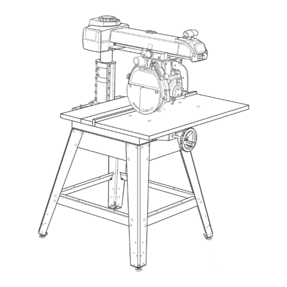
Page 16: Features
METHOD OF OPERATION: The column at the back of the saw supports the radial arm. The arm can be raised or lowered to change the blade height or swiveled left and right for a miter cut. A yoke fits into... - Page 17 See Figure 8B. BLADE - For maximum performance, man 40-tooth, 10 in. carbide-tipped with your saw. It is a high-quality combination suitable for ripping and crosscut operations. recommended Accessory section of this manual. The blade is powered by the main motor and turned off by the switch.
- Page 18 Located on the left side of the arm on the carriage cover. See Figure 8C. COLUMN - Upright housing at the back of the saw, consisting of a column support and a column tube.
- Page 19 MOTOR (13/6.5 AMP) - Powers the blade and is controlled by the switch and key at the front of the arm. The powerful induction motor has a capacitor start. It is mounted in the yoke and rotated with the bevel index knob and bevel lock lever. See Figure 8B. RIP SCALES - Show the distance from the fence to the blade.
- Page 20 CAUTION: Perform all the procedures in both the Assembly and Adjustments sections before using the saw. Run a check on your saw frequently, referring to the Adjustments section. Failure to perform the adjustments in the initial set up or on a frequent basis can result in poor performance or machine damage.
-
Page 21: Mounting Saw To Leg Stand
4 hex nuts (5/16-18) • Place the saw on top of the leg stand so the holes in the saw base line up with the holes on top of the leg stand braces. • Put a washer on a screw, and put the screw and washer into the hole in the saw base. - Page 22 Iockwasher. Do not risk serious injury or damage to the saw by failing to replace these parts. • Tighten the carriage lock knob, on the carriage cover on the left of the arm, to lock the yoke assembly in place.
-
Page 23: Removing The Blade
4 hex nuts (5/16-18) 4 flat washers (5/16 in.) • Attach the supports to the side of the saw base. There are holes in both sides of each support. The long side of each support (with the slotted holes) fits against the saw base. -
Page 24: Setting The Arm Lock Knob
YOKE CLAMP See Figures 16A and 16B. The yoke clamp keeps the yoke from rotating on the carriage when you want the saw blade to be station- ary. Use this procedure to check and set the yoke clamp. • Release the yoke lock handle (below the arm on the right side) so the motor can be rotated. - Page 25 SETTING BEVEL LOCK See Figures 17A -17C. The bevel lock lever locks the blade at desired angles other than the preset positive stop angles. The bevel lock lever is preset at the factory but may need readjustment after shipping or extended use. Check for overtightness or looseness and make any neces- sary adjustments as follows:...
- Page 26 Replace the rear cover and rear cover screws. • Tighten screws securely. HEXBOLT(2) HEXNUT(2) CR_FT_MRN °RADIAL SAW 315.273731 COLUMN ADJUSTING See Figures 19A - 19D. The purpose of this procedure is to check whether the inner column tube is snug in the housing and to remove any looseness.
- Page 27 • Rotation check: To check the rotation, hold the front of the arm with one hand and grasp the top of the column support with the other. Press the arm to the side. If there is play between the column support and the column tube, it needs to be adjusted.
- Page 28 Loose carriage bearings permit the blade to wander slightly while cutting, which will result in a poor cut and more wear and tear on the saw. Use the following steps to check for tightness and to then adjust the bearings if needed.
- Page 29 Move the arm to the opposite side and repeat the above procedure. When the opposite side is level, recheck the first side to make sure that it is still accurate and even. • Return the saw and motor to normal height and position. rRRFTSMRN ° RADIAL SAW315.273731 RIGHTSIDE TABLESUPPORT...
- Page 30 • Snap the U-clip onto the front edge of the saw base. Line up the hole in the U-clip with the saw base hole just to the left of the center notch in saw base. See Figure 22B. • Place the table, top up, on the table supports so the center counterbored hole lines up over the hole in the U-clip.
- Page 31 LEVELING FRONT TABLE See Figure 23. If there are any high or low areas on the front table, they should be removed by adjusting the leveling screws in the center holes on the front table. • Place the rear table on its edge across the front table to check for gaps.
- Page 32 See Figures 25A and 25B. • Collect the blade and hardware that were removed earlier. Place the inner blade washer, saw blade, outer blade washer, and blade nut on the blade arbor. See Figure 25A. Note: The flat concave side of blade washers go against the blade.
- Page 33 ALIGN RIVING KNIFE TO BLADE See Figures 26A - 26C. When ripping the riving knife must be centered with the blade to ride in the middle of the kerf and keep it from binding. Binding pinches the blade. Blade pinching can cause kickback. There are two pairs of anti-kickback ,_!1 WARNING: Failure to use the riving knife, hold...
- Page 34 The control cut device offers many benefits. As it increases operator control, it eliminates the risk in a cross cut of the saw "climbing" out and over the workpiece at the operator. Feed control of the blade as it cuts through the workpiece increases, as does the accuracy of the cut.
- Page 35 (0 °) and leave it unlocked. • Lower the arm with the elevating handwheel until the saw blade just clears the front table. Lock the yoke lock handle (right side of saw, below yoke) and the bevel lock lever.
- Page 36 Place the square flat against the blade between two teeth. • If both the top and bottom of the saw blade are flat against the square, no adjustment is needed. • If the saw blade gaps at the top or bottom, remove the bevel index cap by removing the two phillips head screws (below the handle).
- Page 37 The blade must be angled at 90 ° to the fence when the handle is at the front of the saw. If not, kickback could result during a cross cut. Kickback can cause serious injury by throw- ing the workpiece toward the operator, tn addi-...
- Page 38 PARALLELING BLADE TO TABLE See Figures 31A-31C. This procedure squares the blade to the table at 90 ° bevel so horizontal cuts will be accurate. This also reduces kickback, as well as splintering and burning of the cut edges of the workpiece. If the blade is not at 90 °...
- Page 39 ALIGNING RIP SCALE See Figures 32A - 32B. The rip scale indicators on the arm show the distance between the blade and the rip fence. The upper scale is used when the fence is positioned directly behind the front table. The lower scale is used when the fence is at the extreme rear, directly in front of the column.
- Page 40 The control cut device offers many benefits. As it increases operator control, it eliminates the risk in a cross cut of the saw "climbing" out and over the workpiece at the operator. Feed control of the blade as it cuts through the workpiece increases, as does the accuracy of the cut.
- Page 41 It can make dado or molding cuts with special attachments. This saw is designed to cut wood and wood composi- tion products only. The three-prong plug must be plugged into a match- ing outlet that is properly installed and grounded according to all local codes and ordinances.
- Page 42 The yellow switch key prevents accidental starting of the main power switch when saw is not being used. To activate the switch, insert the switch key and lift switch to ON position. To lock the switch once it has been pressed to OFF, remove the yellow key.
- Page 43 Use a pushblock when the blade is between 1/2 in. and 2 in. from the fence. (If the cut is narrower than 1/2 in., use a different saw.) Refer to the drawings and instructions provided so you can make safer and more precise cuts.
- Page 44 • Release the switch trigger and let the carriage return to the back. Turn the saw off with the switch on the arm but hold the handle until the blade stops rotating. Adjust the height with the elevating handwheel so the blade will rotate freely in the kerf.
- Page 45 • Release the switch trigger and let the carriage return to the back. Turn the saw off with the switch on the arm but hold the handle until the blade stops rotating. Adjust the height with the elevating handwheel so the blade will rotate freely in the kerf.
- Page 46 CRAFfSMRN _RADIALSAW 315.273731 • Release the switch trigger and let the carriage return to the back. Turn the saw off with the switch on the arm but hold the handle until the blade stops rotating. Adjust the height with the elevating handwheel so the blade will rotate freely in the kerf.
- Page 47 • Release the switch trigger and let the carriage return to the back. Turn the saw off with the switch on the arm but hold the handle until the blade stops rotating. Adjust the height with the elevating handwheel so the blade will rotate freely in the kerf.
- Page 48 Push the workpiece past the pawls with push- blocks and pushsticks to finish the cut. • If the blade jams, turn the saw off with the switch on the arm, remove the yellow key, and wait for the blade to fully stop before freeing it.
- Page 49 • Cut a kerf. Turn the saw on with the switch on the arm. Lower the blade about 1/16 in. into the table to cut a shallow groove. Turn the saw off and remove the yellow key.
- Page 50 • Make sure the wood does not touch the blade before you turn on the saw with the switch on the arm. Let the blade build up to full speed before it contacts the wood.
- Page 51 Lower the blade with the elevating handwheel. • Make sure the wood is not touching the blade. Insert the key and turn on the saw. Let the blade build up to full speed before contacting the work- piece. WARNING:...
- Page 52 GENERAL MAINTENANCE WARNING: When servicing, use only identical Craftsman replacement parts. Use of any other part may create a hazard or cause product damage. WARNING: To prevent accidental starting that could cause possible serious personal injury, turn off the saw with the switch on the arm, remove the switch key, and unplug the saw before working on the radial saw.
- Page 53 PROBLEM Saw does not start. Motor does not reach full speed or power. Motor stalls, blows fuses, or trips circuit breakers. Motor overheats. CAUSE 1. Motor cord or control-cut cord is not plugged in. 2. Cord or switch is damaged.
-
Page 54: Setting The Yoke Clamp
Saw stalls when ripping. rRRFT,_MRN ° RADIALSAW 315.273731 CAUSE 1. Blade is warped. 2. Saw is not mounted securely. 3. Work surface is uneven. 1. Motor needs attention. 1. Track is dirty or sticky. 2. Carriage bearings are bad. -
Page 55: Setting The Bevel Lock Lever
PROBLEM Handwheel is hard to turn or column binds, Saw burns or scores edges of wood in cut. Bevel cuts are not true. CAUSE 1. Sawdust has collected on the elevating shaft. 2. Column is out of alignment. 1. Column tube is too loose in the column support. -
Page 56: Adjustments
PROBLEM Miter or cross cuts are not true. Wood edges away from fence when ripping. Depth of cut varies from one end of wood to the other. Riving knife strikes wood during a cut. rRRFT,_MRN ° RADIALSAW 315.273731 CAUSE 1. Scale pointer is not correct. 2. - Page 57 PROBLEM Saw blade tends to push wood to one side when cross cutting. CAUSE 1. Blade is heeling. 2. Column tube is loose in column support. 3. Arm is loose or misaligned. 4. Fence/tables are not straight. 5. Blade or teeth are bent or dull.
- Page 58 RADIAL ARM SAW- MODEL NO. 315.273731 ARM SAW or when ordering repair parts. I The model number will be found on a plate attached to the base. Always mention the model number in all correspondence regarding your RADIAL SEE FIGURE I...
- Page 59 • CRAFTSMAN ARM SAW or when ordering repair parts. I The model number will be found on a plate attached to the base. Always mention the model number in all correspondence PART NUMBER DESCRIPTION 976830-001 Lower Arm Cover ... ** STD611006 * Screw (10-16 x 5/8 in.
- Page 60 CRAFTSMAN RADIAL ARM SAW- ber in all correspondence regarding your RADIAL ARM SAW or when ordering repair parts. The model number will be found on a plate attached to the base. Always mention the model num- 13... SEE FIGURE D...
- Page 61 RADIAL ARM SAW- ber in all correspondence regarding your RADIAL ARM SAW or when ordering repair parts. The model number will be found on a plate attached to the base. Always mention the model num- PARTS LIST FOR FIGURE B...
- Page 62 RADIAL ARM SAW- MODEL NO. 315.273731 ARM SAW or when ordering repair parts. I The model number will be found on a plate attached to the base. Always mention the model number in all correspondence regarding your RADIAL FIGURE C...
- Page 63 • CRAFTSMAN ARM SAW or when ordering repair parts. I The model number will be found on a plate attached to the base. Always mention the model number in all correspondence PART NUMBER DESCRIPTION 977242-001 Lower Front/Rear Brace ... 976303-001 Leg ...
- Page 64 CRAFTSMAN RADIAL ARM SAW- ber in all correspondence regarding your RADIAL ARM SAW or when ordering repair parts. The model number will be found on a plate attached to the base. Always mention the model num- FIGURE D MODEL NO. 315.273731...
- Page 65 RADIAL ARM SAW- ber in all correspondence regarding your RADIAL ARM SAW or when ordering repair parts. The model number will be found on a plate attached to the base. Always mention the model num- PARTS LIST FOR FIGURE D...
- Page 66 CRAFTSMAN RADIAL ARM SAW- ber in all correspondence regarding your RADIAL ARM SAW or when ordering repair parts. The model number will be found on a plate attached to the base. Always mention the model num- FIGURE E MODEL NO. 315.273731 I:RRFTSMRN •...
- Page 67 RADIAL ARM SAW- ber in all correspondence regarding your RADIAL ARM SAW or when ordering repair parts. The model number will be found on a plate attached to the base. Always mention the model num- PARTS LIST FOR FIGURE E...
- Page 68 CRAFTSMAN RADIAL ARM SAW- ber in all correspondence regarding your RADIAL ARM SAW or when ordering repair parts. The model number will be found on a plate attached to the base. Always mention the model num- FIGURE F MODEL NO. 315.273731 SEE FIGURE G •...
- Page 69 RADIAL ARM SAW- ber in all correspondence regarding your RADIAL ARM SAW or when ordering repair parts. The model number will be found on a plate attached to the base. Always mention the model num- PARTS LIST FOR FIGURE F...
- Page 70 CRAFTSMAN RADIAL ARM SAW- ber in all correspondence regarding your RADIAL ARM SAW or when ordering repair parts. The model number will be found on a plate attached to the base. Always mention the model num- SEE FIGURE F FIGURE G MODEL NO.
- Page 71 RADIAL ARM SAW- ber in all correspondence regarding your RADIAL ARM SAW or when ordering repair parts. The model number will be found on a plate attached to the base. Always mention the model num- PARTS LIST FOR FIGURE G...
- Page 72 CRAFTSMAN RADIAL ARM SAW- MODEL NO. 315.273731 ARM SAW or when ordering repair parts. I The model number will be found on a plate attached to the base. Always mention the model number in all correspondence regarding your RADIAL j"...
- Page 73 • CRAFTSMAN ARM SAW or when ordering repair parts. I The model number will be found on a plate attached to the base. Always mention the model number in all correspondence PART NUMBER DESCRIPTION 610122-006 * Screw (8-32 x 5/8 in. Pan Hd.) ...
- Page 74 RADIAL ARM SAW- MODEL NO. 315.273731 ARM SAW or when ordering repair parts. I The model number will be found on a plate attached to the base. Always mention the model number in all correspondence regarding your RADIAL FIGURE I...
- Page 75 • CRAFTSMAN ARM SAW or when ordering repair parts. I The model number will be found on a plate attached to the base. Always mention the model number in all correspondence PART NUMBER DESCRIPTION 976366-001 Guard Screw (10-24 Slotted) ... 1 977237-001 Inner Lower Guard ...
- Page 76 RADIAL ARM SAW- MODEL NO. 315.273731 ARM SAW or when ordering repair parts. I The model number will be found on a plate attached to the base. Always mention the model number in all correspondence regarding your RADIAL SEE FIGURE K j"...
- Page 77 • CRAFTSMAN ARM SAW or when ordering repair parts. I The model number will be found on a plate attached to the base. Always mention the model number in all correspondence PART NUMBER DESCRIPTION 607818-002 Sleeve Bearing ... 990908-009 Screw (6-19 x 5/8 in. Pan Hd.) ...
- Page 78 RADIAL ARM SAW- MODEL NO. 315.273731 ARM SAW or when ordering repair parts. I The model number will be found on a plate attached to the base. Always mention the model number in all correspondence regarding your RADIAL FIGURE K...
- Page 79 • CRAFTSMAN ARM SAW or when ordering repair parts. I The model number will be found on a plate attached to the base. Always mention the model number in all correspondence PART NUMBER DESCRIPTION ** STD510803 * Screw (8-32 x 3/8 in. Pan Hd.) ...
- Page 80 1. The Part Number 2. The Part Description 3. The Model Number: 315.273731 4. The name of the item: 254 mm (10 in.) Professional Radial Arm Saw DOES NOT END A TOP-NOTCH SERVICE THEIR KNOWLEDGE OF OUR NEW...