Table of Contents
Advertisement
Available languages
Available languages
Quick Links
Air Conditioning Control System
MA Remote Controller
TAR-40MAAU
Installation Manual
This installation manual describes how to install the MA Remote Controller for use with Air Conditioning
System, direct expansion type CITY MULTI air conditioner indoor units ("-A" type and later), and NV-
series and P-series air conditioners.
Be sure to read the Simple Manual, Installation Manual, and the Instruction Book before proceeding
with the installation. Failure to follow the instructions may result in equipment damage.
For information on how to wire and install the air conditioning units, refer to the installation manual.
1
Safety Precautions
• Thoroughly read the following safety precautions prior to installation.
• Observe these precautions carefully to ensure safety.
WARNING
Indicates a risk of death or serious injury.
CAUTION
Indicates a risk of serious injury or structural damage.
• After reading this manual, pass it on to the end user to retain for future reference.
• Keep this manual for future reference and refer to it as necessary. This manual should be made
available to those who repair or relocate the controller. Make sure that the manual is forwarded to
future end users.
All electric work must be performed by qualified personnel.
For distribution to dealers and contractors
– 1 –
<ORIGINAL>
WT09197X01
Advertisement
Table of Contents

Related Manuals for Mitsubishi Electric Trane TAR-40MAAU


Summary of Contents for Mitsubishi Electric Trane TAR-40MAAU
- Page 1 <ORIGINAL> Air Conditioning Control System WT09197X01 MA Remote Controller TAR-40MAAU Installation Manual For distribution to dealers and contractors This installation manual describes how to install the MA Remote Controller for use with Air Conditioning System, direct expansion type CITY MULTI air conditioner indoor units (“-A” type and later), and NV- series and P-series air conditioners.
-
Page 2: General Precautions
General precautions WARNING Do not install the unit in a place where large amounts of To reduce the risk of injury or electric shock, stop the oil, steam, organic solvents, or corrosive gases, such operation and switch off the power supply before as sulfuric gas, are present or where acidic/alkaline cleaning, maintaining, or inspecting the controller. - Page 3 Precautions during wiring WARNING To reduce the risk of damage to the controller, Use properly rated breakers and fuses (breaker, local malfunctions, smoke, or fire, do not connect the power switch <switch + fuse>, no-fuse breaker). cable to the signal terminal block. Breaker with a breaking capacity greater than the specified capacity may cause electric shock, Properly secure the cables in place and provide...
-
Page 4: Additional Precautions
Vibrations or shocks to the controller may damage the controller or cause the controller to fall. This controller is designed for exclusive use with the Building Management System by Mitsubishi Electric. Secure the cable with a clamp. The use of this controller for with other systems or for Do not use solderless terminals to connect cables to other purposes may cause malfunctions. - Page 5 Component names and supplied parts The following parts are included in the box. Top case *1 Bottom case *2 Parts name Qty. Appearance Remote controller (top case) Right figure *1 Remote controller (bottom case) Right figure *2 Roundhead cross slot screws M4×30 Wood screw 4.1×16 (for direct wall installation) Simple Manual...
- Page 6 How To Wire Transmission Line The wiring is different when the remote controller is connected to a CITY MULTI control system (“-A” type and later) and when it is connected to NV-series and P-series air conditioners (A control type). The wiring also differs with the system configuration. Check the system used. 1.
- Page 7 2. Connecting to NV-series and P-series air conditioners The remote controller wiring depends on the system configuration. Check the system configuration. Wire the remote controller as shown in the example below. The numbers (1) to (3) in the figure correspond to items (1) to (3) in the following description. [1] Connecting the remote controller for each refrigerant system (Standard 1:1, simultaneous twin, simultaneous triple, simultaneous four) Connect to TB5...
-
Page 8: How To Install
(4) Total length of remote controller wiring • The MA Remote Controller can be wired up to 450 m (1476 ft). CAUTION - The wiring cannot be connected to TB5 of the indoor unit of the same refrigerant system. If so connected, the system will not operate normally. - Remote controllers cannot be wired together. -
Page 9: Installation Space
Do not install the controller in a place where To avoid deformation and malfunction, do the difference between the remote controller not install the remote controller in direct surface temperature and the actual room sunlight or where the ambient temperature temperature will be great. - Page 10 3 Prepare the bottom case of the remote controller. Top case Bottom case 4 Connect the remote controller cable to the terminal block on the bottom case. Peel off the remote controller cable sheath as shown below to connect to the terminal block properly. Secure the remote controller cable so that the peeled part of the cable will fit into the case.
- Page 11 5 Install the bottom case. ■ Installation using a switch box • Secure at least two corners of the switch box with screws. ■ Direct wall installation • Thread the cable through the groove. • Secure at least two corners of the remote controller with screws. •...
- Page 12 8 Insert the wires into the clamp. Clamp Important Hold the wires in place with the clamp to prevent undue force from being applied to the terminal block and causing cable breakage. Insert the wires. 9 Install the top case on the bottom case. Two mounting tabs are at the top of the top case.
- Page 13 • Uninstalling the top case 1 Uninstalling the top case Insert a flat-tip screwdriver with a blade width of 3-5 mm (1/8-13/64 inch) into the latches at the bottom of the remote controller and lift the latches. Then, pull up the top case. ■...
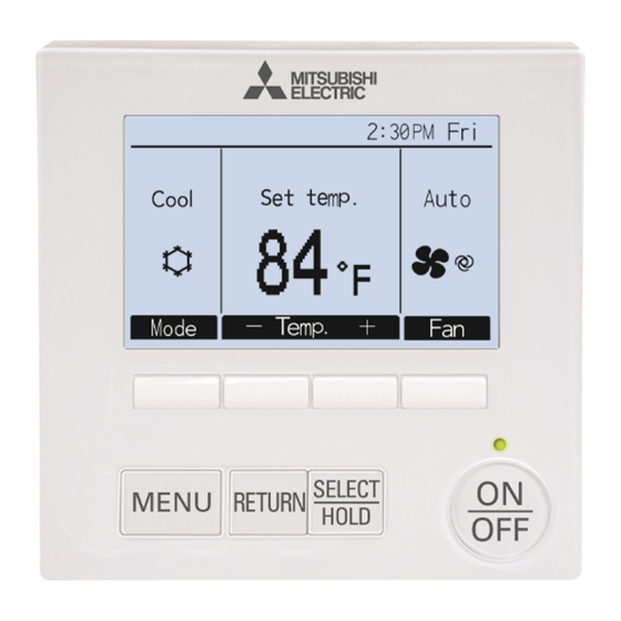
- Page 14 Remote controller button functions (7) Backlit LCD (2) Function buttons F1, F2, F3, and F4 from the left (6) Operation indicator (1) ON/OFF button (4) RETURN button (3) MENU button (5) SELECT/HOLD button (1) ON/OFF button Pressing the MENU button will bring up the Main Use to turn ON/OFF the indoor unit.
-
Page 15: Turning On The Power
Button operations on the Main menu Cursor Move the cursor to the desired function with the F2 and F3 buttons, and press the SELECT button to go to the next page. Password may be required. Button function guide will appear at the bottom of the screens. - Page 16 Test run Note: Maintenance password is required. (1) Read the section about Test run in the indoor unit Installation Manual before performing a test run. (2) At the Main display, press the Setting button and select Service>Test run>Test run. (3) Press the ON/OFF button to cancel the test run if necessary. (4) Refer to the indoor unit Installation Manual for the detailed information about test run and for how to handle the errors that occur during a test run.
-
Page 17: Daylight Saving Time
(3) Daylight saving time The start/end time for daylight saving time can be set. The daylight saving time function will be activated based on the setting contents. • If a given system has a system controller, disable this setting to keep the correct time. - Page 18 Display setting menu (1) Main display setting [Button operation] Move the cursor to “Full/Basic,” and use the F3 or F4 button to select the display mode “Full” or “Basic.” (The factory setting is “Full.”) Full mode (Example) Basic mode (Example) Note: This setting is only for the Main display.
- Page 19 [1] Clock display [Button operation] 1 Select “Clock” from the display details setting screen, and press the F4 button (Change) to bring up the clock display setting screen. 2 Use the F1 through F4 buttons to select “Yes” (display) or “No” (non- display) and its format for the Status display and the Main display.
-
Page 20: Contrast•Brightness
[5] Backlight The backlight lighting-up time can be set. [Button operation] Move the cursor to “Backlight” from the display details setting screen, and select the desired time (5/10/20/30/60 seconds) with the F4 button. (The factory setting is “30” seconds.) Note: This setting is effective on the Status display and the Main display. [6] LED lighting The LED lighting can be set to either “Yes”... -
Page 21: Service Menu
Operation setting menu (1) Auto mode setting [Button operation] Whether or not to use the Auto (single set point) or Auto (dual set points) mode can be selected by using the F3 or F4 button. This setting is valid only when indoor units with the Auto mode function are connected. (The factory setting is “Yes”.) Press the SELECT button to save the changes made. - Page 22 (1) Test run (CITY MULTI and NV/P-series) Select “Test run” from the Service menu to bring up the Test run menu. • Test run: Select this option to perform a test run. • Drain pump test run: Select this option to perform a test run on the drain pump on the indoor unit.
- Page 23 Note: · Refer to the indoor unit Installation Manual for information about the factory settings of indoor units, function setting numbers, and setting values. · Be sure to write down the settings for all functions if any of the initial settings has been changed after the completion of installation work.
- Page 24 Table1. Function setting options Mode No. Mode Settings Setting No. Unit numbers Automatic recovery after Disable Set “Grp.” for the Unit number. power failure These settings apply to all the Enable (Four minutes of standby time connected indoor units. is required after the restoration of power.) Thermistor selection Average temperature reading of the...
- Page 25 2 When the search is completed, the smallest address of the indoor units that are connected to the remote controller and the address of the interlocked LOSSNAY unit will appear. “--” will appear if no LOSSNAY unit is interlocked with the indoor units. If no settings need to be made, press the RETURN button to go back to the Settings menu.
- Page 26 (6) Check Select “Check” on the Service menu to bring up <NV/P-series> <CITY MULTI> the Check menu screen. The type of menu that appears depends on the type of indoor units that are connected (CITY MULTI or NV/P-series). (When CITY MULTI is connected, only “Error history”...
- Page 27 <NV/P-series> <CITY MULTI> When there is no error history [Resetting the error history] 1 Press the F4 button (Reset) on the screen that shows the error history. A confirmation screen will appear asking if you want to delete the error history.
-
Page 28: Remote Controller Check
(9) Remote controller information The following information of the remote controller in use can be checked. • Model name • Software version • Serial number [Button operation] 1 Select “Others” from the Service menu. 2 Select “Remote controller information”. Remote controller check When the remote controller does not work properly, use the remote controller checking function to troubleshoot the problem. -
Page 29: Precauciones De Seguridad
<Traducción de la instrucción original> Sistema de control de aire acondicionado WT09197X01 Controlador remoto MA TAR-40MAAU Manual de instalación Para ser entregado a distribuidores y contratistas Este manual de instalación describe cómo instalar el controlador remoto MA para su uso con el sistema de aire acondicionado, las unidades interiores de aire acondicionado CITY MULTI de tipo expansión directa (tipos “-A”... -
Page 30: Precauciones Generales
Precauciones generales ADVERTENCIA No instale la unidad en un lugar donde haya grandes Para reducir el riesgo de lesiones o de descargas cantidades de aceite, vapor, disolventes orgánicos o eléctricas, pare el funcionamiento del controlador y gases corrosivos como el gas sulfúrico, o donde se desconéctelo de la toma de corriente antes de usen frecuentemente soluciones ácidas, alcalinas o limpiarlo, realizar labores de mantenimiento o revisarlo. - Page 31 Precauciones durante la instalación eléctrica ADVERTENCIA Para reducir el riesgo de daño del controlador, Use disyuntores y fusibles de un régimen adecuado anomalías, humo o incendios, no conecte el cable de (disyuntor, interruptor local <interruptor + fusible>, alimentación al bloque de terminales de señales. disyuntor sin fusible).
-
Page 32: Precauciones Adicionales
Fije el cable con una abrazadera. exclusivo con el sistema de gestión de edificios de No use terminales sin soldar para conectar los cables Mitsubishi Electric. al bloque de terminales. El uso de este controlador con otros sistemas o para Dichas terminales sin soldar podrían entrar en... - Page 33 Nombres de los componentes y partes suministradas En la caja se incluyen las siguientes piezas: Carcasa superior *1 Carcasa inferior *2 Nombre de la pieza Cantidad Aspecto Controlador remoto (Carcasa superior) Figura derecha *1 Controlador remoto (Carcasa inferior) Figura derecha *2 Tornillos en cruz de cabeza redonda M4×30 Tornillo para madera 4,1×16...
- Page 34 Cómo cablear la línea de transmisión El cableado es diferente cuando el controlador remoto está conectado a un sistema de control CITY MULTI (tipo “-A” o posterior) y cuando está conectado a un aire acondicionado de las series NV y P (tipo de control A).
- Page 35 2. Conexión a los aparatos de aire acondicionado de las series NV y P El cableado del controlador remoto depende de la configuración del sistema. Compruebe la configuración del sistema. Cablee el controlador remoto tal como se muestra en el siguiente ejemplo. Los números (1) a (3) en la ilustración corresponden a los elementos (1) a (3) en la siguiente descripción.
-
Page 36: Cómo Instalar
(4) Longitud total del cableado del controlador remoto • El controlador remoto MA puede cablearse hasta una distancia de 450 m (1476 pies). PRECAUCIÓN - El cableado no puede conectarse al TB5 de la unidad interior del mismo sistema de refrigeración. De hacerlo, el sistema no funcionará con normalidad. -
Page 37: Espacio De Instalación
No instale el controlador en un lugar donde Para evitar deformaciones y anomalías, no haya una diferencia considerable entre la instale el controlador remoto bajo la luz temperatura de la superficie del controlador directa del sol o en lugares donde la remoto y la temperatura ambiente. - Page 38 3 Prepare la carcasa inferior del controlador remoto. Carcasa superior Carcasa inferior 4 Conecte el cable del controlador remoto al bloque de terminales de la carcasa inferior. Pele el revestimiento del cable del controlador remoto tal como se muestra para conectarlo adecuadamente al bloque de terminales.
- Page 39 5 Instale la carcasa inferior. ■ Instalación con caja de interruptores • Fije con tornillos al menos dos esquinas de la caja de interruptores. ■ Instalación directa en la pared • Introduzca el cable por la ranura. • Fije con tornillos al menos dos esquinas del controlador remoto. •...
- Page 40 8 Inserte los cables en la abrazadera. Abrazadera Importante Fije los cables con la abrazadera para evitar que se rompan si se aplica fuerza excesiva al bloque de terminales. Inserte los cables. 9 Coloque la carcasa superior sobre la carcasa inferior. Hay dos lengüetas en la parte superior de la carcasa superior.
- Page 41 • Desinstalación de la carcasa superior 1 Desinstalación de la carcasa superior Inserte un destornillador de punta plana con un ancho de hoja de entre 3 a 5 mm (1/8 a 13/64 pulgadas) en los cierres de la parte inferior del controlador remoto y levante los cierres. A continuación, levante la carcasa superior.
- Page 42 Funciones de los botones del controlador remoto (7) LCD retroiluminada (2) Botones de función F1, F2, F3 y F4, desde la izquierda (6) Indicador de funcionamiento (1) Botón ON/OFF (4) Botón VOLVER (3) Botón MENÚ (5) Botón ACEPTAR/ BLOQUEO (1) Botón ON/OFF Al pulsar el botón MENÚ...
-
Page 43: Conectar La Alimentación
Funcionamiento de los botones en el Menú principal Mueva el cursor a la función deseada con los Cursor botones F2 y F3 y pulse el botón ACEPTAR para ir a la siguiente página. Puede que se pida una contraseña. La guía de la función de los botones aparece en el fondo de las pantallas. -
Page 44: Modo Prueba
Modo prueba Nota: Se necesita contraseña de mantenimiento. (1) Lea la sección acerca del modo de prueba en el manual de instalación de la unidad interior antes de ejecutar una prueba. (2) En la pantalla principal, pulse el botón Ajuste y seleccione Revisión > Modo prueba > Modo prueba. (3) Pulse el botón ON/OFF para cancelar el modo de prueba si fuera necesario. - Page 45 (3) Horario de verano Es posible ajustar la hora de inicio/fin del horario de verano. La función de horario de verano se activará en función de la configuración. • Si un determinado sistema tiene un controlador de sistema, desactive este ajuste para conservar la hora correcta. •...
- Page 46 Menú Configuración de pantalla (1) Pantalla principal [Funcionamiento del botón] Desplace el cursor a “Completo/Básico” y utilice el botón F3 o F4 para seleccionar el modo de pantalla “Completo” o “Básico”. (El ajuste de fábrica es “Completo”.) Modo Completo (ejemplo) Modo Básico (ejemplo) Nota: Este ajuste es sólo para Ajuste el Menú...
- Page 47 [1] Configurar hora [Funcionamiento del botón] 1 Seleccione “Hora” en la pantalla de ajuste de los detalles de pantalla y pulse el botón F4 (Cambio) para acceder a la pantalla de ajuste Configurar hora. 2 Utilice los botones F1 a F4 para seleccionar “Sí” (visualizar) o “No” (no visualizar) y su formato para la pantalla Ajuste y la pantalla principal.
- Page 48 [5] Retroiluminación Puede configurarse el tiempo durante el que estará activada la retroiluminación. [Funcionamiento del botón] Mueva el cursor a la opción “Retroilumin.” en la pantalla de ajuste Detalles de pantalla y seleccione el tiempo que desee (5/10/20/30/60 segundos) con el botón F4. (El ajuste de fábrica es “30” segundos.) Nota: Este ajuste es efectivo en la pantalla Estado y en la pantalla principal.
- Page 49 Menú Configuración funcionamiento (1) Ajuste de modo automático [Funcionamiento del botón] El uso o no uso del modo automático (punto de ajuste simple) o automático (puntos de ajuste dobles) puede seleccionarse mediante el uso del botón F3 o F4. Este ajuste únicamente es válido si se conectan unidades interiores con la función de modo automático.
- Page 50 (1) Modo de prueba (CITY MULTI y series NV/P) Seleccione “Modo prueba” en el menú Revisión para acceder al menú Modo prueba. • Modo prueba: Seleccione esta opción para ejecutar una prueba. • Modo prueba bomba de drenaje: Seleccione esta opción para ejecutar una prueba de la bomba de drenaje en la unidad interior.
- Page 51 Nota: · Consulte el manual de instalación de la unidad interior para obtener información acerca de la configuración de fábrica de las unidades interiores, los número de configuración de funciones y los valores de configuración. · Asegúrese de anotar los ajustes para todas las funciones si alguno de los ajustes iniciales se ha cambiado tras completar el trabajo de instalación.
- Page 52 Tabla 1. Opciones de la configuración de funciones N.º de modo Modo Ajustes Nº de ajuste Números de unidad Recuperación automática Inhabilitar Establezca “Grp.” como número de tras fallo de alimentación unidad. Habilitar (Son necesarios cuatro Estos ajustes se aplican para todas minutos de tiempo en espera tras la las unidades interiores conectadas.
- Page 53 2 Una vez completada la búsqueda, aparecerá la dirección más pequeña de las unidades interiores que están conectadas al controlador remoto y la dirección de la unidad LOSSNAY interconectada. Se mostrará “--” si no hay ninguna unidad LOSSNAY interconectada con las unidades interiores.
- Page 54 (6) Comprobación Seleccione “Comprobación” en el menú <Series NV/P> <CITY MULTI> Revisión para acceder a la pantalla del Menú comprobación. El tipo de menú que aparece depende del tipo de las unidades interiores conectadas (CITY MULTI o series NV/P). (Si está conectada CITY MULTI, solo aparecerá “Histórico de errores”...
- Page 55 <Series NV/P> <CITY MULTI> Si no hay historial de errores [Restablecer el historial de errores] 1 Pulse el botón F4 (Borrar) en la pantalla que muestra el historial de errores. Aparecerá una pantalla de confirmación que preguntará si desea borrar el historial de errores. 2 Pulse el botón F4 (OK) para borrar el historial de errores.
- Page 56 (9) Información del controlador remoto Es posible verificar la siguiente información del controlador remoto. • Nombre del modelo • Versión del software • Número de serie [Funcionamiento del botón] 1 Seleccione “Otros” en el menú Revisión. 2 Seleccione “Información de control remoto”. Revisión de controladores remotos Si el controlador remoto no funciona correctamente, utilice la función de comprobación de controlador remoto para localizar el problema.
- Page 57 Nota: Este equipo ha sido sometido a pruebas y se ha determinado que cumple con los límites establecidos para un dispositivo digital Clase B, conforme a la Parte 15 de las Normas de la FCC. Estos límites están diseñados para proporcionar protección razonable contra interferencia dañina en una instalación residencial.
- Page 60 HEAD OFFICE: 1340 SATELLITE BLVD, SUWANEE GA 30024 USA WT09197X01...