Table of Contents
Advertisement
Quick Links
SPEF 3A2 C
Fault indicator
User´s manual and Technical description
REGISTERS
0
1
I
L1
2
I
L2
3
I
L3
( )
4
t
I
5
[ ]
o I
(
6
t
I o
∆
7
I
∆
(
8
t
SPA
RS 489 001 - AA
1
B470959B
f
x
n = 50Hz
SPEF 3A2 C
60Hz
U
=24V-
aux
OPERATION IND.
0
[ ]
1
>
A
I
start
>
[ ]
2
I
alarm
A
>
[ ]
3
I
A
start
o
>
[ ]
>
%
4
I
alarm
o
∆
>
5
I
start
A
∆
)
[ ]
>
>
%
6
I
alarm
[ ]
%
>
)
[ ]
%
I
Serial port
01234
Ser.No.
3 >
I
∆ I
I
I
I
I
IRF
>
o
I
L2
L3
L1
∆
I >
RESET
STEP
> [ ]
I
A
t
>
[ ]
s
>
[ ]
I
A
o
PROGRAM
>
t
[ ]
s
o
∆ >
[ ]
%
I
t ∆
>
[ ]
s
SGF
ALARM
SGB
X1
18
Advertisement
Table of Contents

Related Manuals for ABB SPEF 3A2 C


Summary of Contents for ABB SPEF 3A2 C
- Page 1 SPEF 3A2 C Fault indicator User´s manual and Technical description n = 50Hz 3 > ∆ I > SPEF 3A2 C 60Hz ∆ I > =24V- REGISTERS OPERATION IND. > start > alarm RESET > start STEP > > alarm ∆...
-
Page 2: Table Of Contents
SPEF 3A2 C 1MRS 751719-MUM EN Issued 1999-11-25 Fault indicator Modified 2002-10-09 Version B (replaces 34 SPEF 1 EN1) Checked MK Approved OL Data subject to change without notice Characteristics ........................ 3 Contents Application ........................3 Alarming functions ......................3 Connection diagram ....................... -
Page 3: Characteristics
∆ I alarm Analog output I Definite time earth-fault load indicator Analog output I Analog output ∆ I Control Phase unbalance input BS indicator Serial communication SERIAL I/O funcblck Fig. 1. Function of the fault indicator type SPEF 3A2 C. -
Page 4: Connection Diagram
Reset indicators ALARM SGB /2 Reset indicators and output relays SGB /3 Reset indicators, output relays and registers Reset SPEF 3A2 C Fig 2. Connection diagram of the fault indicator. Abbreviations of signal names Phase currents Residual current ∆I Phase unbalance... -
Page 5: Connections
Inputs for phase current Connections Terminal Function X1-1 X1-2 X1-3 X1-7 Common ground for phase currents Cable's shield Auxiliary supply voltage 24 V dc Terminal Function X1-17 +24 Vdc X1-18 GND, internally connected to X1-7 Protective earth Terminal Function Protective earth terminal Remote reset input BS The fault indicator can be externally reset via the control input Terminal Function... - Page 6 Fibre optic bus connection module SPA-ZC17 or SPA-ZC22 with cable SPA-ZP14A2 Terminal Function X2-2 TxD, output X2-3 RxD, input X2-7 The fault indicator SPEF 3A2 C is interfaced with the SPA serial communication bus through a 9- pole, D-type subminiature connector X2 located on the front panel of the device.
-
Page 7: Technical Data (Modified 2002-10)
Energizing inputs Primary Output of the Technical data Current current sensors (modified 2002-10) (KOHU24A/KOKU 073G2) Measurement range of phase input currents 0…700 A 0…0.174 A *) Thermal withstand capability - continuously 400 A 0.1 A - for 1 s 20 kA 2.3 A *) Dynamic current withstand, half-wave value... - Page 8 - air discharge 8 kV Environmental conditions Enviromental condition tests are made on SPEF 3A2 C without current sensors. Specified ambient service temperature range -10°C to +55°C Transport and storage temperature range -40°C to +70°C, 72 h + 72 h...
-
Page 9: Description Of Function
The overcurrent unit of the fault indicator SPEF The operation of overcurrent stage is provided Description of 3A2 C is designed for single-phase, two-phase or with a latching facility (SGF1/4) keeping the functions three-phase operation. alarm output energized, although the signal which caused the operation disappears. -
Page 10: Resetting Possibilities
Phase unbalance The phase unbalance unit constitutes a definite PROGRAM push-button, pressing the RESET unit time current unbalance unit. and PROGRAM push-buttons simultaneously, by remote control over the external input or over The unbalance of the power system is detected the SPA bus using the command V101 or the by monitoring the highest and the lowest phase V102. -
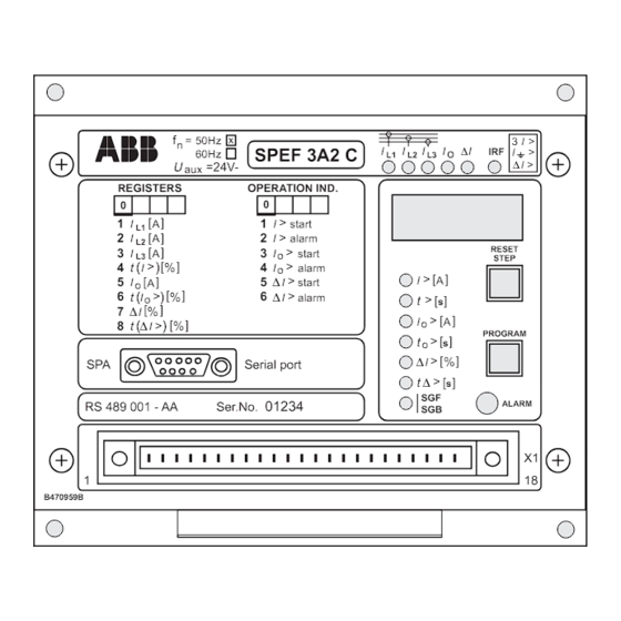
Page 11: Front Panel
Ser.No. number Output and input connections B470959B Fig 3. Front panel of the fault indicator SPEF 3A2 C Each stage has its own operation indicator shown If the start of a stage does not last long enough Operation as a red figure to the left on the digital display. -
Page 12: Settings
The setting values are shown by the right-most Note! Settings three digits of the display. A lit indicator close to A symbol "//" in the text indicates that the a setting value symbol shows which setting value following item is found in a submenu. is indicated on the display. -
Page 13: Programming Switches
Additional functions required by individual The number of the switches, 1…8, and the Programming applications are selected by means of the switch positions, 0 and 1, are indicated when the switches switchgroup SGF, indicated on the front panel. switchgroups are being set. In normal service only the checksums are shown. - Page 14 Switch Function Factory setting SGF1/5 Latching function for the alarm signal of earth fault stage I >. When SGF1/5=0, the alarm signal returns to its initial state, i.e. the output relay drops off, when the signal causing the operation falls below the starting level.
-
Page 15: Measured Data
Remote reset input Switch Function Factory switchgroup SGB setting SGB/1 Remote reset of indicators When SGB/1=0, the indicators are not reset by signal BS. When SGB/1=1, the indicators are reset by signal BS. SGB/2 Remote reset of indicators and output relays When SGB/2=0, the indicators and output relays are not reset by signal BS. -
Page 16: Recorded Data
When the fault indicator provides an alarm RESET and PROGRAM simultaneously) of Recorded data signal, the current values at the moment of the the relay erases all the contents of the register alarm, the duration of the start of the different blocks. - Page 17 Register Recorded information Duration of the latest starting situation (n) of stage ∆I> expressed as a percentage of the set operating time t∆. When the concerned stage has alarmed the counter reading is 100 per cent. // Duration of event (n-1) starting of stage ∆I> // Duration of event (n-2) starting of stage ∆I>...
-
Page 18: Main Menus And Submenus Of Settings And Registers
Status of external relay t> to> t∆> blocking / control signal Communication rate Loss of bus traffic time Relay unit identification address for communication setting [Bd] counter 0..255 s Fig 4. Main menus and submenus of the fault indicator SPEF 3A2 C... - Page 19 The measures required for entering a submenu detail on data sheet "General characteristics of or a setting mode, the setting procedure and the D-type relay modules". Below a short guide. how to use the TEST mode are described in Desired step or operation Push-button Action Forward step in main or submenu...
-
Page 20: Event Codes
When the fault indicator module SPEF 3A2 C capable of memorizing up to eight events. If Event codes is linked to a control data communicator over more than eight events occur before the content the SPA bus, the module will provide time- of the buffer has been sent to the communicator stamped events e.g. -
Page 21: Data To Be Transferred Over The Bus
In addition to the event data transfer the SPA The password can be changed via the SPA bus or Data to be bus allows reading of all input data (I-data), with the push-buttons on the unit. When using transferred setting values (S-data), information recorded in the SPA bus, the password must be opened. - Page 22 Data Code Data flow Value range direction Memorized start of stage I> 0 = I>-stage not started 1 = I>-stage started Memorized alarm of stage I> 0 = I>-stage not alarmed 1 = I>-stage alarmed Memorized start of stage I >...
- Page 23 Re-reading of event register time, channel number and event code Type designation of the module SPEF 3A2 C Reading of module status data 0 = normal state 1 = module been subject to automatic reset 2 = overflow of event register...
-
Page 24: Fault Codes
X1-6. Further, in most ordered. Below some fault codes that might fault situations, an auto-diagnostic fault code is appear with the unit SPEF 3A2 C: shown on the display. This fault code consists of Fault code... -
Page 25: Dimensions And Instructions For Mounting
= 50 Hz BA f = 60 Hz Information required with order Example 1. Quantity and type designation 15 pcs SPEF 3A2 C-AA 2. Ordering number RS 489 001-AA 3. Rated frequency = 50 Hz 4. Accessories 15 pcs SPA-ZP 27A07... - Page 28 ABB Oy Substation Automation P.O.Box 699 FIN-65101 VAASA Finland Tel. +358 (0)10 22 11 Fax.+358 (0)10 22 41094 www.abb.com/substationautomation...